2003 NISSAN X-TRAIL open hood
[x] Cancel search: open hoodPage 663 of 3066

TROUBLE DIAGNOSIS
ATC-85
C
D
E
F
G
H
I
K
L
MA
B
AT C
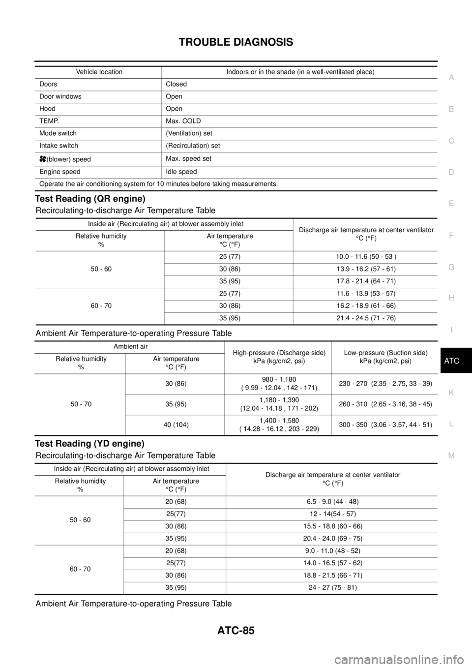
Test Reading (QR engine)
Recirculating-to-discharge Air Temperature Table
Ambient Air Temperature-to-operating Pressure Table
Test Reading (YD engine)
Recirculating-to-discharge Air Temperature Table
Ambient Air Temperature-to-operating Pressure Table
Vehicle location Indoors or in the shade (in a well-ventilated place)
Doors Closed
Door windows Open
Hood Open
TEMP. Max. COLD
Mode switch (Ventilation) set
Intake switch (Recirculation) set
(blower) speedMax. speed set
Engine speed Idle speed
Operate the air conditioning system for 10 minutes before taking measurements.
Inside air (Recirculating air) at blower assembly inlet
Discharge air temperature at center ventilator
°C(°F) Relative humidity
%Air temperature
°C(°F)
50 - 6025 (77) 10.0 - 11.6 (50 - 53 )
30 (86) 13.9 - 16.2 (57 - 61)
35 (95) 17.8 - 21.4 (64 - 71)
60 - 7025 (77) 11.6 - 13.9 (53 - 57)
30 (86) 16.2 - 18.9 (61 - 66)
35 (95) 21.4 - 24.5 (71 - 76)
Ambient air
High-pressure (Discharge side)
kPa (kg/cm2, psi)Low-pressure (Suction side)
kPa (kg/cm2, psi) Relative humidity
%Air temperature
°C(°F)
50 - 7030 (86)980 - 1,180
( 9.99 - 12.04 , 142 - 171)230 - 270 (2.35 - 2.75, 33 - 39)
35 (95)1,180 - 1,390
(12.04 - 14.18 , 171 - 202)260 - 310 (2.65 - 3.16, 38 - 45)
40 (104)1,400 - 1,580
( 14.28 - 16.12 , 203 - 229)300 - 350 (3.06 - 3.57, 44 - 51)
Inside air (Recirculating air) at blower assembly inlet
Discharge air temperature at center ventilator
°C(°F) Relative humidity
%Air temperature
°C(°F)
50 - 6020 (68) 6.5 - 9.0 (44 - 48)
25(77) 12 - 14(54 - 57)
30 (86) 15.5 - 18.8 (60 - 66)
35 (95) 20.4 - 24.0 (69 - 75)
60 - 7020 (68) 9.0 - 11.0 (48 - 52)
25(77) 14.0 - 16.5 (57 - 62)
30 (86) 18.8 - 21.5 (66 - 71)
35 (95) 24 - 27 (75 - 81)
Page 750 of 3066

BL-6
HOOD
Install in the reverse order of removal.
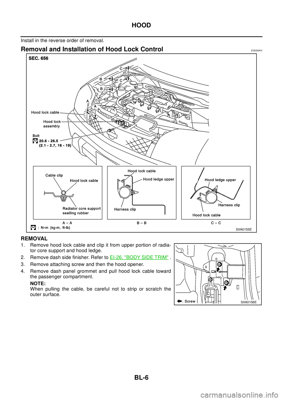
Removal and Installation of Hood Lock ControlEIS000KH
REMOVAL
1. Remove hood lock cable and clip it from upper portion of radia-
tor core support and hood ledge.
2. Remove dash side finisher. Refer toEI-26, "
BODY SIDE TRIM".
3. Remove attaching screw and then the hood opener.
4. Remove dash panel grommet and pull hood lock cable toward
the passenger compartment.
NOTE:
When pulling the cable, be careful not to strip or scratch the
outer surface.
SIIA0155E
SIIA0156E
Page 751 of 3066

HOOD
BL-7
C
D
E
F
G
H
J
K
L
MA
B
BL
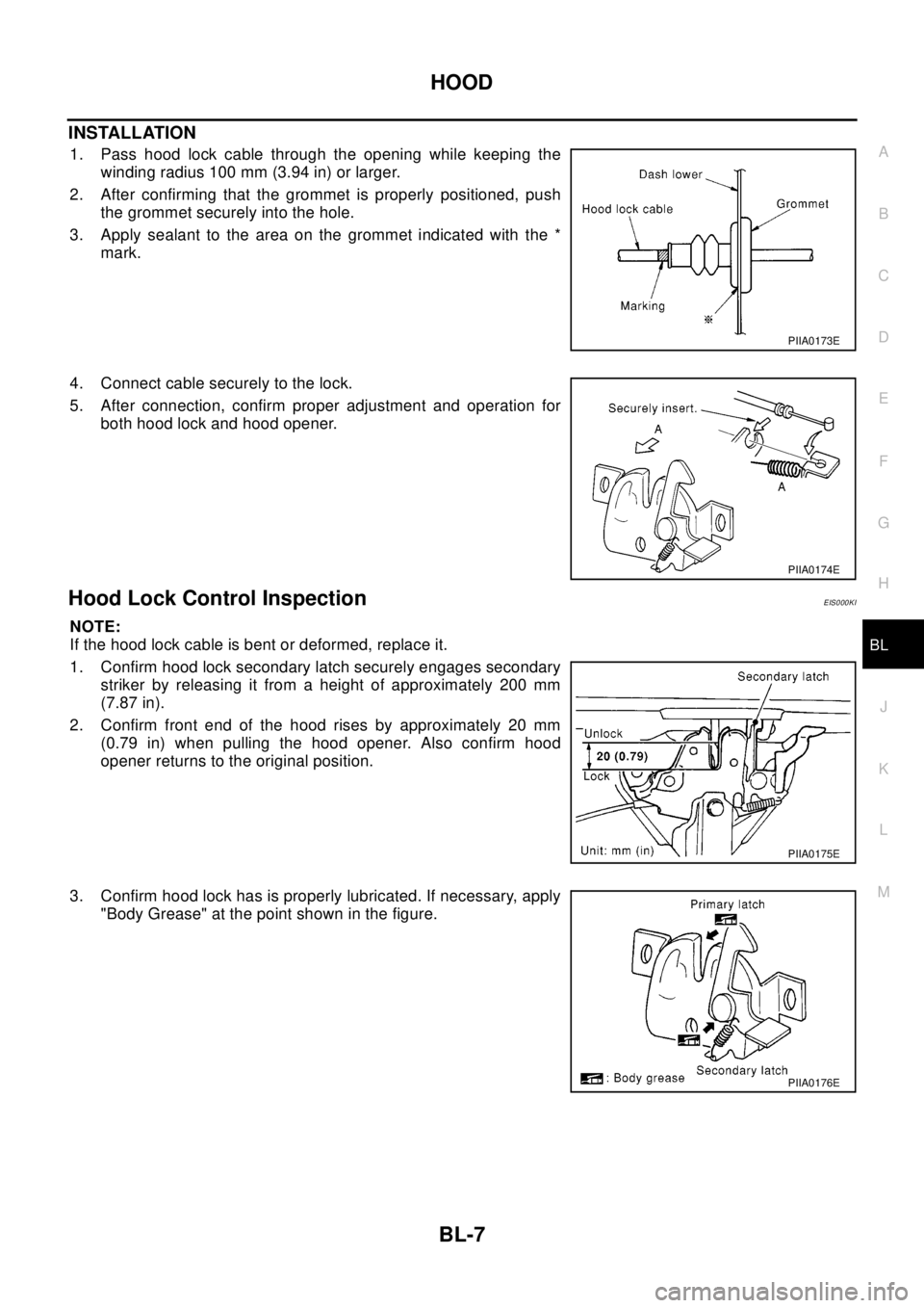
INSTALLATION
1. Pass hood lock cable through the opening while keeping the
winding radius 100 mm (3.94 in) or larger.
2. After confirming that the grommet is properly positioned, push
the grommet securely into the hole.
3. Apply sealant to the area on the grommet indicated with the *
mark.
4. Connect cable securely to the lock.
5. After connection, confirm proper adjustment and operation for
both hood lock and hood opener.
Hood Lock Control InspectionEIS000KI
NOTE:
If the hood lock cable is bent or deformed, replace it.
1. Confirm hood lock secondary latch securely engages secondary
striker by releasing it from a height of approximately 200 mm
(7.87 in).
2. Confirm front end of the hood rises by approximately 20 mm
(0.79 in) when pulling the hood opener. Also confirm hood
opener returns to the original position.
3. Confirm hood lock has is properly lubricated. If necessary, apply
"Body Grease" at the point shown in the figure.
PIIA0173E
PIIA0174E
PIIA0175E
PIIA0176E
Page 911 of 3066
![NISSAN X-TRAIL 2003 Electronic Repair Manual TROUBLE DIAGNOSIS
BRC-43
[4WD/ABS]
C
D
E
G
H
I
J
K
L
MA
B
BRC
3.CHECK CONTINUITY BETWEEN IGNITION SWITCH AND ABS WARNING LAMP.
lDisconnect 4WD/ABS control unit connector.
lCheck continuity between ign NISSAN X-TRAIL 2003 Electronic Repair Manual TROUBLE DIAGNOSIS
BRC-43
[4WD/ABS]
C
D
E
G
H
I
J
K
L
MA
B
BRC
3.CHECK CONTINUITY BETWEEN IGNITION SWITCH AND ABS WARNING LAMP.
lDisconnect 4WD/ABS control unit connector.
lCheck continuity between ign](/manual-img/5/57402/w960_57402-910.png)
TROUBLE DIAGNOSIS
BRC-43
[4WD/ABS]
C
D
E
G
H
I
J
K
L
MA
B
BRC
3.CHECK CONTINUITY BETWEEN IGNITION SWITCH AND ABS WARNING LAMP.
lDisconnect 4WD/ABS control unit connector.
lCheck continuity between ignition switch and 4WD/ABS control module terminal No. 4. (Open circuit
check)
Is inspection result OK?
YES >> Continuity exists. Connect 4WD/ABS control module connector, check again.
NO >> Continuity does not exist. Check ABS warning lamp path.
4.CHECK FUSE.
lCheck if Fuse No.8 is working normally.
Is the check result OK?
YES >> Repair or replace the harness in between 4WD/ABS control unit and IGN.
NO >> Replace the fuse and replace again.
lIf the figure of the monitor is with in±10% of the set value of E-TS solenoid electric current, 4WD/ABS C/
U is operating normally.Check for electric control coupling ASSY is required.
4WD warning lamp does not illuminate with ignition ON.EFS001BR
1.INSPECTION OF BLOWN 4WD WARNING LAMP BULB
lRemove glove box on the passenger side and disconnect the 4WD/ABS control unit connector.
lConfirm continuity between 4WD/ABS control unit connector terminals No. 3 (IGN) and No. 4 (ABS warn-
ing lamp).
Is inspection result OK?
YES >> GO TO 3. (Continuity exists.)
NO >>
lCheck 4WD warning lamp harness.
lRemove meter control module assembly and check for blown 4WD warning lamp bulb.
2.4WD ACTUATOR RELAY HARNESS INSPECTION
lOpen the hood and check that the 4WD relay is properly installed in the relay box.
lConfirm continuity between 4WD/ABS control unit connector terminals No. 7 (4WD warning lamp) and No.
104 (ground).
lConfirm continuity between 4WD/ABS control unit connector terminals No. 3 (IGN) and No. 18 (4WD
actuator relay).
Is inspection result OK?
YES >> Continuity exists. Connect 4WD/ABS control unit connector, check again.
NO >> Check ABS warning lamp harness.
4WD warning lamp does not go out several seconds after engine is started.
(Drive mode indicator lamp goes out.)
EFS001BS
1.USING CONSULT, PERFORM SELF-DIAGNOSIS.
4WD warning lamp does not go out several seconds after the engine is started. (Drive mode indicator lamp
goes out.)
Is inspection result OK?
YES >> No malfunction detected. Perform inspection again.
NO >>
lDetermine the location of the malfunction according to the result of self-diagnosis using CON-
SULT. (Malfunction is present in the 4WD system.)
lCONSULT-II does not display ABS -related trouble codes. Proceed to 2.
Page 1178 of 3066
![NISSAN X-TRAIL 2003 Electronic Repair Manual EC-64
[QR (WITH EURO-OBD)]
TROUBLE DIAGNOSIS
Basic Inspection
EBS00BMK
1.INSPECTION START
1. Check service records for any recent repairs that may indicate a related problem, or a current need for
sch NISSAN X-TRAIL 2003 Electronic Repair Manual EC-64
[QR (WITH EURO-OBD)]
TROUBLE DIAGNOSIS
Basic Inspection
EBS00BMK
1.INSPECTION START
1. Check service records for any recent repairs that may indicate a related problem, or a current need for
sch](/manual-img/5/57402/w960_57402-1177.png)
EC-64
[QR (WITH EURO-OBD)]
TROUBLE DIAGNOSIS
Basic Inspection
EBS00BMK
1.INSPECTION START
1. Check service records for any recent repairs that may indicate a related problem, or a current need for
scheduled maintenance.
2. Open engine hood and check the following:
–Harness connectors for improper connections
–Wiring harness for improper connections, pinches and cut
–Vacuum hoses for splits, kinks and improper connections
–Hoses and ducts for leaks
–Air cleaner clogging
–Gasket
3. Confirm that electrical or mechanical loads are not applied.
–Headlamp switch is OFF.
–Air conditioner switch is OFF.
–Rear window defogger switch is OFF.
–Steering wheel is in the straight-ahead position, etc.
4. Start engine and warm it up until engine coolant temperature
indicator points the middle of gauge.
Ensure engine stays below 1,000 rpm.
5. Run engine at about 2,000 rpm for about 2 minutes under no-
load.
6. Make sure that no DTC is displayed with CONSULT-II or GST.
OK or NG
OK >> GO TO 3.
NG >> GO TO 2.
2.REPAIR OR REPLACE
Repair or replace components as necessary according to corresponding “Diagnostic Procedure”.
>> GO TO 3
SEF983U
SEF976U
SEF977U
Page 1343 of 3066
![NISSAN X-TRAIL 2003 Electronic Repair Manual DTC P0420 THREE WAY CATALYST FUNCTION
EC-229
[QR (WITH EURO-OBD)]
C
D
E
F
G
H
I
J
K
L
MA
EC
DTC P0420 THREE WAY CATALYST FUNCTIONPFP:20905
On Board Diagnosis LogicEBS00B6A
The ECM monitors the switchi NISSAN X-TRAIL 2003 Electronic Repair Manual DTC P0420 THREE WAY CATALYST FUNCTION
EC-229
[QR (WITH EURO-OBD)]
C
D
E
F
G
H
I
J
K
L
MA
EC
DTC P0420 THREE WAY CATALYST FUNCTIONPFP:20905
On Board Diagnosis LogicEBS00B6A
The ECM monitors the switchi](/manual-img/5/57402/w960_57402-1342.png)
DTC P0420 THREE WAY CATALYST FUNCTION
EC-229
[QR (WITH EURO-OBD)]
C
D
E
F
G
H
I
J
K
L
MA
EC
DTC P0420 THREE WAY CATALYST FUNCTIONPFP:20905
On Board Diagnosis LogicEBS00B6A
The ECM monitors the switching frequency ratio of heated oxygen
sensors 1 and 2.
A three way catalyst (Manifold) with high oxygen storage capacity
will indicate a low switching frequency of heated oxygen sensor 2.
As oxygen storage capacity decreases, the heated oxygen sensor 2
switching frequency will increase.
When the frequency ratio of heated oxygen sensors 1 and 2
approaches a specified limit value, the three way catalyst (Manifold)
malfunction is diagnosed.
DTC Confirmation ProcedureEBS00B6B
NOTE:
If “DTC Confirmation Procedure” has been previously conducted, always turn ignition switch “OFF” and wait at
least 10 seconds before conducting the next test.
WITH CONSULT-II
TESTING CONDITION:
lOpen engine hood before conducting the following procedure.
lDo not hold engine speed for more than the specified minutes below.
1. Turn ignition switch “ON”.
2. Select “DTC & SRT CONFIRMATION” then “SRT WORK SUP-
PORT”modewithCONSULT-II.
3. Start engine.
4. Rev engine up to 2,000 to 3,000 rpm and hold it for 3 consecu-
tive minutes then release the accelerator pedal completely.
If "INCMP" of "CATALYST" changed to "COMPLT", go to step 7
5. Wait 5 seconds at idle.
PBIB0067E
DTC No. Trouble diagnosis name DTC detecting condition Possible cause
P0420
0420Catalyst system effi-
ciency below threshold
lThree way catalyst (Manifold) does not oper-
ate properly.
lThree way catalyst (Manifold) does not have
enough oxygen storage capacity.
lThree way catalyst (Manifold)
lExhaust tube
lIntake air leaks
lFuel injectors
lFuel injector leaks
lSpark plug
lImproper ignition timing
PBIB0566E
Page 1526 of 3066
![NISSAN X-TRAIL 2003 Electronic Repair Manual EC-412
[QR (WITHOUT EURO-OBD)]
TROUBLE DIAGNOSIS
Basic Inspection
EBS00BMX
1.INSPECTION START
1. Check service records for any recent repairs that may indicate a related problem, or a current need for NISSAN X-TRAIL 2003 Electronic Repair Manual EC-412
[QR (WITHOUT EURO-OBD)]
TROUBLE DIAGNOSIS
Basic Inspection
EBS00BMX
1.INSPECTION START
1. Check service records for any recent repairs that may indicate a related problem, or a current need for](/manual-img/5/57402/w960_57402-1525.png)
EC-412
[QR (WITHOUT EURO-OBD)]
TROUBLE DIAGNOSIS
Basic Inspection
EBS00BMX
1.INSPECTION START
1. Check service records for any recent repairs that may indicate a related problem, or a current need for
scheduled maintenance.
2. Open engine hood and check the following:
–Harness connectors for improper connections
–Wiring harness for improper connections, pinches and cut
–Vacuum hoses for splits, kinks and improper connections
–Hoses and ducts for leaks
–Air cleaner clogging
–Gasket
3. Confirm that electrical or mechanical loads are not applied.
–Headlamp switch is OFF.
–Air conditioner switch is OFF.
–Rear window defogger switch is OFF.
–Steering wheel is in the straight-ahead position, etc.
4. Start engine and warm it up until engine coolant temperature
indicator points the middle of gauge.
Ensure engine stays below 1,000 rpm.
5. Run engine at about 2,000 rpm for about 2 minutes under no-
load.
6. Make sure that no DTC is displayed with CONSULT-II or GST.
OK or NG
OK >> GO TO 3.
NG >> GO TO 2.
2.REPAIR OR REPLACE
Repair or replace components as necessary according to corresponding “Diagnostic Procedure”.
>> GO TO 3.
SEF983U
SEF976U
SEF977U
Page 1787 of 3066
![NISSAN X-TRAIL 2003 Electronic Repair Manual TROUBLE DIAGNOSIS
EC-673
[YD]
C
D
E
F
G
H
I
J
K
L
MA
EC
1.INSPECTION START
1. Check service records for any recent repairs that may indicate a related problem.
2. Check the current need for scheduled NISSAN X-TRAIL 2003 Electronic Repair Manual TROUBLE DIAGNOSIS
EC-673
[YD]
C
D
E
F
G
H
I
J
K
L
MA
EC
1.INSPECTION START
1. Check service records for any recent repairs that may indicate a related problem.
2. Check the current need for scheduled](/manual-img/5/57402/w960_57402-1786.png)
TROUBLE DIAGNOSIS
EC-673
[YD]
C
D
E
F
G
H
I
J
K
L
MA
EC
1.INSPECTION START
1. Check service records for any recent repairs that may indicate a related problem.
2. Check the current need for scheduled maintenance, especially for fuel filter and air cleaner filter. Refer to
MA-7, "
PERIODIC MAINTENANCE".
3. Open engine hood and check the following:
–Harness connectors for improper connections
–Vacuum hoses for splits, kinks, or improper connections
–Wiring for improper connections, pinches, or cuts
4. Start engine and warm it up to the normal operating tempera-
ture.
>> GO TO 2.
2.PREPARATION FOR CHECKING IDLE SPEED
With CONSULT-II
Connect CONSULT-II to the data link connector.
>> GO TO 3.
3.CHECK IDLE SPEED
With CONSULT-II
1. Select “CKPS·RPM (TDC)” in “DATA MONITOR” mode with CONSULT-II.
2. Read idle speed.
OK or NG
OK >>INSPECTION END
NG >> GO TO 4.
4.CHECK FOR INTAKE AIR LEAK
Listen for an intake air leak after the mass air flow sensor.
OK or NG
OK >> GO TO 5.
NG >> Repair or replace.
SEF142I
725±25 rpm
SEF817Y