2003 NISSAN X-TRAIL flat tire
[x] Cancel search: flat tirePage 920 of 3066
![NISSAN X-TRAIL 2003 Electronic Repair Manual BRC-52
[ESP/TCS/ABS]
PRECAUTIONS
[ESP/TCS/ABS]PRECAUTIONSPFP:00001
Precautions for Supplemental Restraint System (SRS) “AIR BAG” and “SEAT
BELT PRE-TENSIONER”
EFS0019N
The Supplemental Restrai NISSAN X-TRAIL 2003 Electronic Repair Manual BRC-52
[ESP/TCS/ABS]
PRECAUTIONS
[ESP/TCS/ABS]PRECAUTIONSPFP:00001
Precautions for Supplemental Restraint System (SRS) “AIR BAG” and “SEAT
BELT PRE-TENSIONER”
EFS0019N
The Supplemental Restrai](/manual-img/5/57402/w960_57402-919.png)
BRC-52
[ESP/TCS/ABS]
PRECAUTIONS
[ESP/TCS/ABS]PRECAUTIONSPFP:00001
Precautions for Supplemental Restraint System (SRS) “AIR BAG” and “SEAT
BELT PRE-TENSIONER”
EFS0019N
The Supplemental Restraint System such as “AIR BAG” and “SEAT BELT PRE-TENSIONER”, used along
with a front seat belt, helps to reduce the risk or severity of injury to the driver and front passenger for certain
types of collision. Information necessary to service the system safely is included in the SRS and SB section of
this Service Manual.
WAR NIN G:
lTo avoid rendering the SRS inoperative, which could increase the risk of personal injury or death
in the event of a collision which would result in air bag inflation, all maintenance must be per-
formed by an authorized NISSAN/INFINITI dealer.
lImproper maintenance, including incorrect removal and installation of the SRS, can lead to per-
sonal injury caused by unintentional activation of the system. For removal of Spiral Cable and Air
Bag Module, see the SRS section.
lDo not use electrical test equipment on any circuit related to the SRS unless instructed to in this
Service Manual. SRS wiring harnesses can be identified by yellow harness connector.
Precautions for Brake SystemEFS0019O
lRecommended fluid is brake fluid “DOT 3” or “DOT 4”.
lNever reuse drained brake fluid.
lBe careful not to splash brake fluid on painted areas; it may cause paint damage. If brake fluid is splashed
on painted areas, wash it away with water immediately.
lNever use mineral oils such as gasoline or kerosene. They will ruin rubber parts of hydraulic system.
lUse flare nut wrench when removing and installing brake tubes.
lAlways torque brake lines when installing.
lBefore working, turn the ignition switch OFF and disconnect the
connectors for the ESP/TCS/ABS actuator and control unit or
the battery terminals.
lBurnish the brake contact surfaces after refinishing or replacing
drums or rotors, after replacing pads or linings, or if a soft pedal
occurs at very low mileage. Refer toBR-10, "
Brake Burnishing
Procedure".
WAR NIN G:
Clean brakes with a vacuum dust collector to minimize risk
of health hazard from powder caused by friction.
Precautions for Brake ControlEFS0019P
lDuring the EPS/TCS/ABS operation, the brake pedal vibrates lightly and its mechanical noise may be
heard. This is a normal condition.
lJust after starting the vehicle after ignition switch ON, the brake pedal may vibrate or the motor operating
noise may be heard from the engine compartment. This is a normal status of the operation check.
lThe stopping distance may be longer than that of vehicles without ABS when the vehicle drives on rough,
gravel, or snowy (fresh deep snow) road.
lIf a malfunction is indicated by the ABS warning lamp, or other warning lamps, collect the necessary infor-
mation from the customer (what symptoms are present under what conditions) and find out the possible
causes before starting the service. Besides the electrical system inspection, check the booster operation,
brake fluid level, and oil leaks.
lIf the tire size and type are used in a improper combination, or the brake pads are not NISSAN genuine
parts, the stopping distance or steering stability may deteriorate.
lIf there is a radio, antenna, or antenna lead-in wire (including wiring) near the control unit, the ESP/TCS/
ABS function may have a malfunction or error.
lIf aftermarket parts (e.g. Car stereo equipment, CD player) have been installed, check the electrical har-
nesses for pinches, open, and improper wiring.
SBR686C
Page 2241 of 3066
FSU-2
PRECAUTIONS
PRECAUTIONS
PFP:00001
CautionEES0006Z
lWhen installing rubber bushings, final tightening must be carried out under unladen conditions with tires
on flat, level ground. Oil will shorten the life of rubber bushings. Be sure to wipe off any spilled oil.
l“Unladen condition” means that fuel, coolant and lubricant are full and ready for drive. However, spare tire,
jack, and hand tools should be unloaded.
lAfter installing the removed suspension parts, always check wheel alignment and adjust if necessary.
lReplace the caulking nut with a new one. Install a new nut without wiping the oil off before tightening.
Precautions for Brake SystemEES000JA
lWhen installing rubber parts, final tightening must be carried out
under unladen condition* with tires on ground.
*: Fuel, radiator coolant and engine oil full. Spare tire, jack,
hand tools and mats in designated positions.
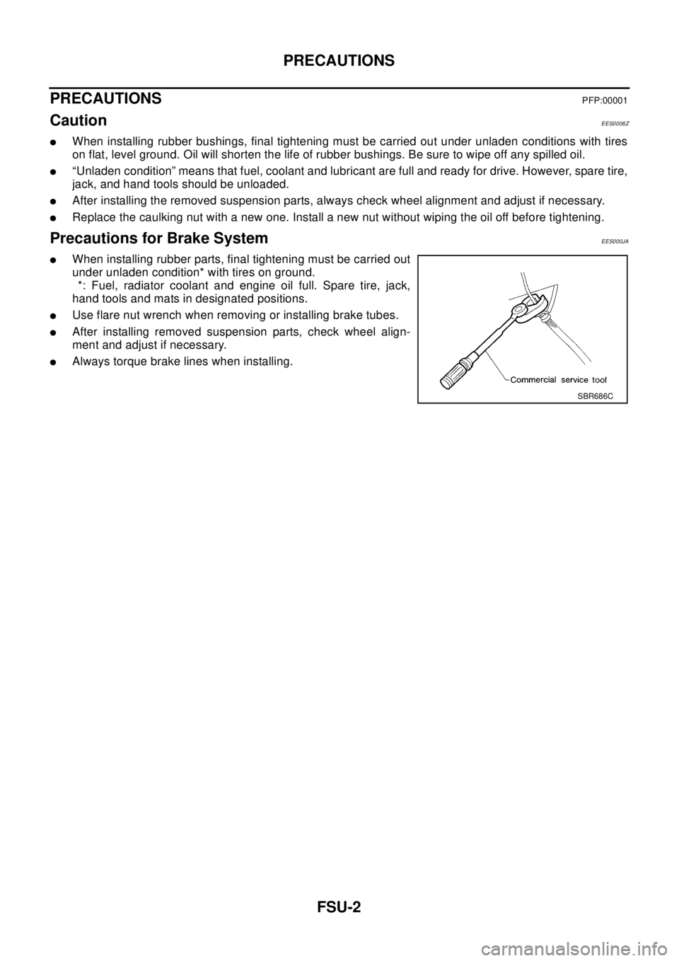
lUse flare nut wrench when removing or installing brake tubes.
lAfter installing removed suspension parts, check wheel align-
ment and adjust if necessary.
lAlways torque brake lines when installing.
SBR686C
Page 2246 of 3066
FRONT SUSPENSION ASSEMBLY
FSU-7
C
D
F
G
H
I
J
K
L
MA
B
FSU
To e - i n
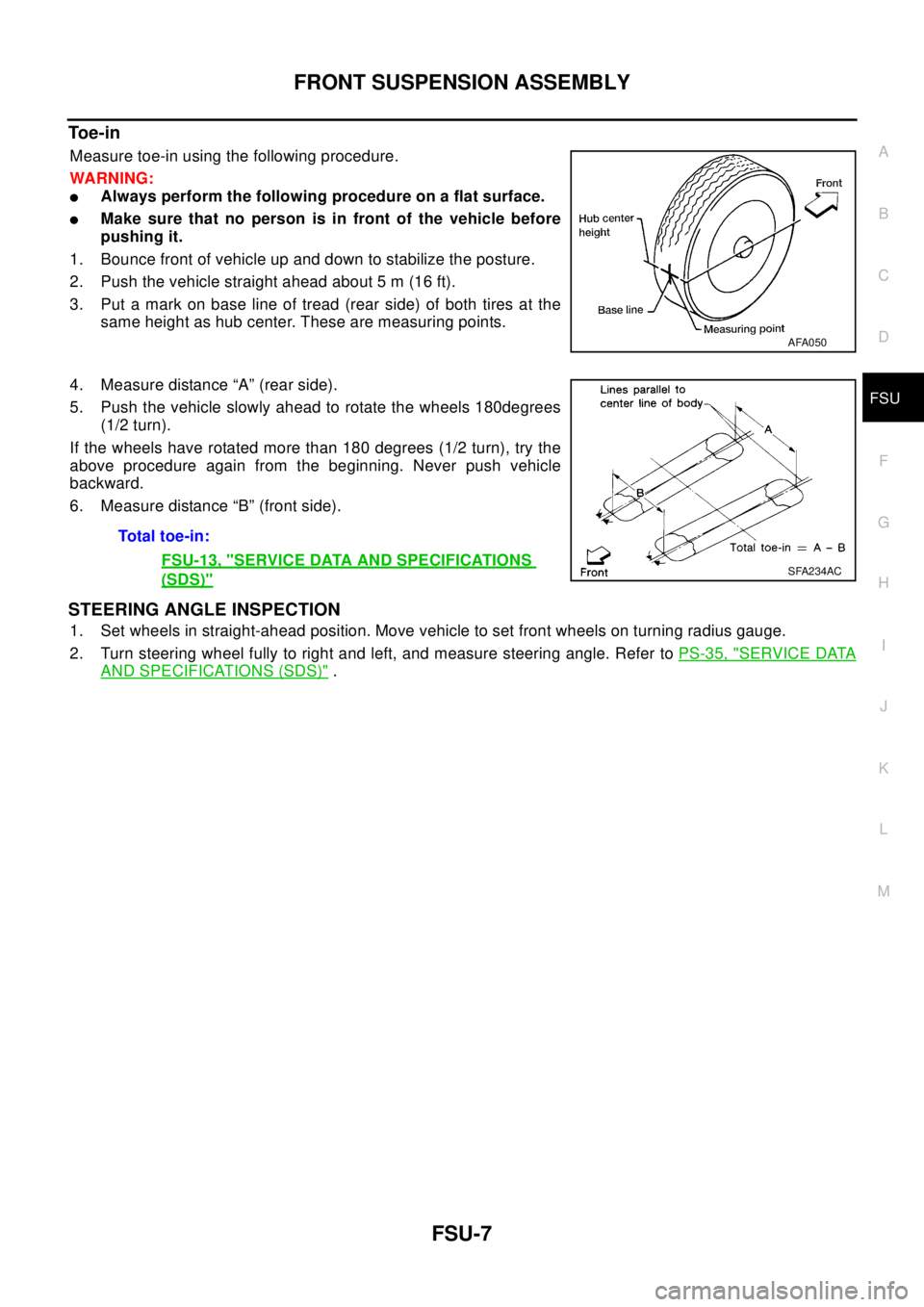
Measure toe-in using the following procedure.
WA RN ING:
lAlways perform the following procedure on a flat surface.
lMake sure that no person is in front of the vehicle before
pushing it.
1. Bounce front of vehicle up and down to stabilize the posture.
2. Push the vehicle straight ahead about 5 m (16 ft).
3. Put a mark on base line of tread (rear side) of both tires at the
same height as hub center. These are measuring points.
4. Measure distance “A” (rear side).
5. Push the vehicle slowly ahead to rotate the wheels 180degrees
(1/2 turn).
If the wheels have rotated more than 180 degrees (1/2 turn), try the
above procedure again from the beginning. Never push vehicle
backward.
6. Measure distance “B” (front side).
STEERING ANGLE INSPECTION
1. Set wheels in straight-ahead position. Move vehicle to set front wheels on turning radius gauge.
2. Turn steering wheel fully to right and left, and measure steering angle. Refer toPS-35, "
SERVICE DATA
AND SPECIFICATIONS (SDS)".
AFA050
Total toe-in:
FSU-13, "
SERVICE DATA AND SPECIFICATIONS
(SDS)"SFA234AC
Page 2249 of 3066
FSU-10
TRANSVERSE LINK
TRANSVERSE LINK
PFP:54500
Removal and InstallationEES00076
REMOVAL
1. Remove steering knuckle from transverse link. Refer toFAX-7, "REMOVAL".
2. Remove mounting nuts and washers on lower portion of stabilizer connecting rod.
3. Slightly loosen transverse link mounting bolts.
4. Remove compression rod bracket mounting bolts.
5. Remove transverse link mounting bolts and nuts, and remove transverse link from suspension member.
INSPECTION AFTER REMOVAL
Visual Inspection
Check transverse link and bushing for deformation, cracks, and other damage. Replace the entire transverse
link assembly if cracks, deformation or any other damage is found.
Ball Joint Inspection
CAUTION:
Before measurement, move the ball joint at least ten times by hand to check for smooth movement.
Oscillating Torque Inspection
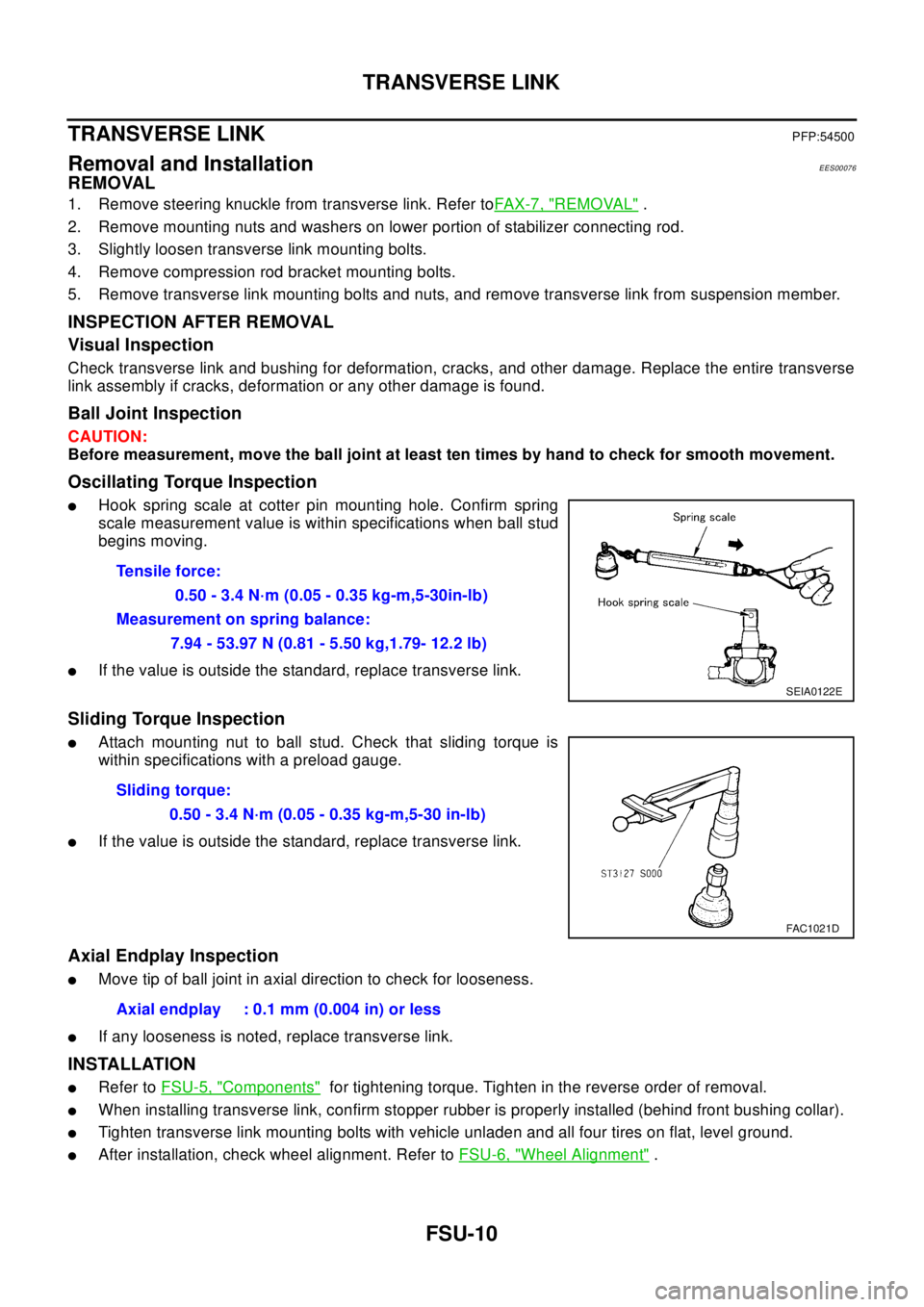
lHook spring scale at cotter pin mounting hole. Confirm spring
scale measurement value is within specifications when ball stud
begins moving.
lIf the value is outside the standard, replace transverse link.
Sliding Torque Inspection
lAttach mounting nut to ball stud. Check that sliding torque is
within specifications with a preload gauge.
lIf the value is outside the standard, replace transverse link.
Axial Endplay Inspection
lMove tip of ball joint in axial direction to check for looseness.
lIf any looseness is noted, replace transverse link.
INSTALLATION
lRefer toFSU-5, "Components"for tightening torque. Tighten in the reverse order of removal.
lWhen installing transverse link, confirm stopper rubber is properly installed (behind front bushing collar).
lTighten transverse link mounting bolts with vehicle unladen and all four tires on flat, level ground.
lAfter installation, check wheel alignment. Refer toFSU-6, "Wheel Alignment". Tensile force:
0.50 - 3.4 N·m (0.05 - 0.35 kg-m,5-30in-lb)
Measurement on spring balance:
7.94 - 53.97 N (0.81 - 5.50 kg,1.79- 12.2 lb)
SEIA0122E
Sliding torque:
0.50 - 3.4 N·m (0.05 - 0.35 kg-m,5-30 in-lb)
FAC1021D
Axial endplay : 0.1 mm (0.004 in) or less
Page 2308 of 3066
SIDE WINDOW GLASS
GW-5
C
D
E
F
G
H
J
K
L
MA
B
GW
SIDE WINDOW GLASSPFP:83300
Removal and InstallationEIS000LV
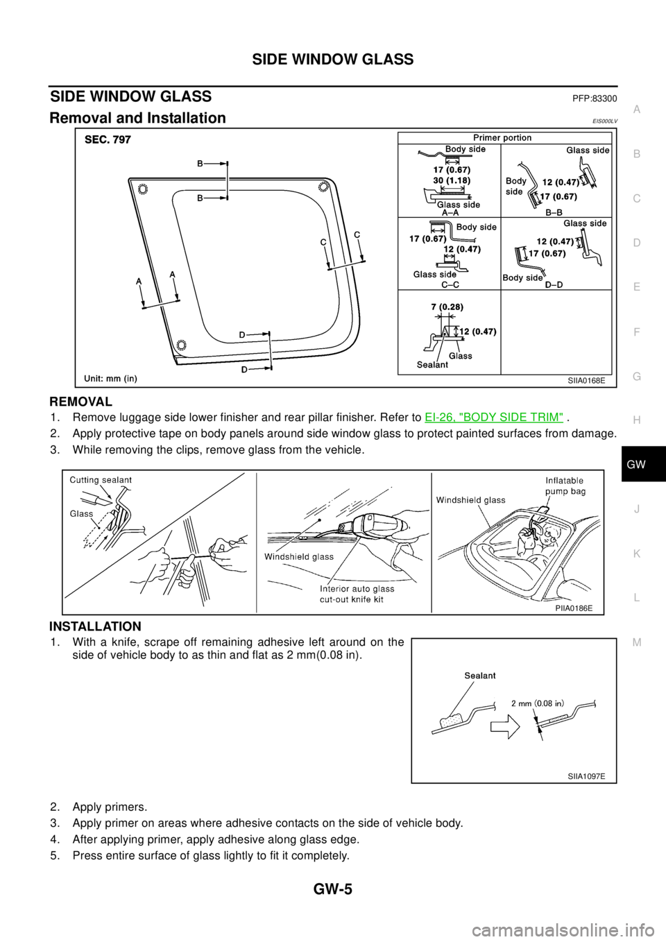
REMOVAL
1. Remove luggage side lower finisher and rear pillar finisher. Refer toEI-26, "BODY SIDE TRIM".
2. Apply protective tape on body panels around side window glass to protect painted surfaces from damage.
3. While removing the clips, remove glass from the vehicle.
INSTALLATION
1. With a knife, scrape off remaining adhesive left around on the
side of vehicle body to as thin and flat as 2 mm(0.08 in).
2. Apply primers.
3. Apply primer on areas where adhesive contacts on the side of vehicle body.
4. After applying primer, apply adhesive along glass edge.
5. Press entire surface of glass lightly to fit it completely.
SIIA0168E
PIIA0186E
SIIA1097E
Page 2311 of 3066
GW-8
BACK DOOR WINDOW GLASS
INSTALLATION
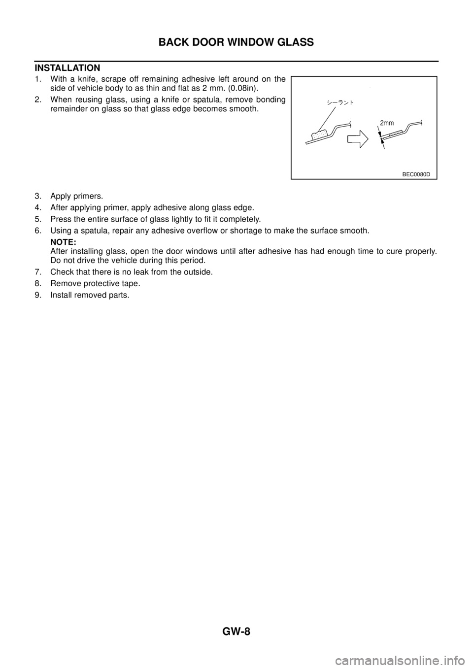
1. With a knife, scrape off remaining adhesive left around on the
side of vehicle body to as thin and flat as 2 mm. (0.08in).
2. When reusing glass, using a knife or spatula, remove bonding
remainder on glass so that glass edge becomes smooth.
3. Apply primers.
4. After applying primer, apply adhesive along glass edge.
5. Press the entire surface of glass lightly to fit it completely.
6. Using a spatula, repair any adhesive overflow or shortage to make the surface smooth.
NOTE:
After installing glass, open the door windows until after adhesive has had enough time to cure properly.
Do not drive the vehicle during this period.
7. Check that there is no leak from the outside.
8. Remove protective tape.
9. Install removed parts.
BEC0080D
Page 2404 of 3066

LT-6
HEADLAMP
Trouble Diagnoses
EKS003CF
Aiming AdjustmentEKS003CG
When performing headlamp aiming adjustment, use an aiming machine, aiming wall screen or headlamp
tester. Aimers should be in good repair, calibrated and operated in accordance with respective operation man-
uals.
If any aimer is not available, aiming adjustment can be done as follows:
For details, refer to the regulations in your own country.
lKeep all tires inflated to correct pressures.
lPlace vehicle and tester on one and same flat surface.
lSee that there is no-load in vehicle (coolant, engine oil filled up to correct level and full fuel tank) other
than the driver (or equivalent weight placed in driver's position).
Symptom Possible cause Repair order
Headlamp LH do not operate.1. Bulb
2. Grounds E24 and E50
3. 15A fuse
4. Lighting switch1. Check bulb.
2. Check grounds E24 and E50.
3. Check 15A fuse (No. 40, located in fuse
and fusible link box). Verify battery posi-
tive voltage is present at terminal 8 of
lighting switch.
4. Check lighting switch.
Headlamp RH do not operate.1. Bulb
2. Grounds E24 and E50
3. 15A fuse
4. Lighting switch1. Check bulb.
2. Check grounds E24 and E50.
3. Check 15A fuse (No. 41, located in fuse
and fusible link box). Verify battery posi-
tive voltage is present at terminal 5 of
lighting switch.
4. Check lighting switch.
High beam LH do not operate, but low
beam LH operates.1. Bulb
2. Open in high beam LH circuit
3. Lighting switch1. Check bulbs.
2. Check the wire between lighting switch
terminal 9 and headlamp LH terminal 1
for an open circuit.
3. Check lighting switch.
Low beam LH does not operate, but high
beam LH operates.1. Bulb
2. Open in low beam LH circuit
3. Lighting switch1. Check bulb.
2. Check the wire between lighting switch
terminal 10 and headlamp LH terminal 3
for an open circuit.
3. Check lighting switch.
High beam RH do not operate, but low
beam RH operates.1. Bulb
2. Open in high beam RH circuit
3. Lighting switch1. Check bulbs.
2. Check the wire between lighting switch
terminal 6 and headlamp RH terminal 1
for an open circuit.
3. Check lighting switch.
Low beam RH does not operate, but high
beam RH operates.1. Bulb
2. Open in low beam RH circuit
3. Lighting switch1. Check bulb.
2. Check the wire between lighting switch
terminal 7 and headlamp RH terminal 3
for an open circuit.
3. Check lighting switch.
High beam indicator does not work.1. Bulb
2. Grounds M27 and M70
3. Open in high beam circuit1. Check bulb in combination meter.
2. Check grounds M27 and M70.
3. Check the wire between lighting switch
terminal 9 and combination meter termi-
nal 61(LHD models) or 50(RHD models)
for an open circuit.
Page 2530 of 3066
MA-38
CHASSIS AND BODY MAINTENANCE
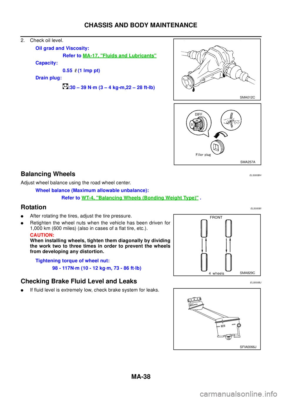
2. Check oil level.
Balancing WheelsELS000BH
Adjust wheel balance using the road wheel center.
RotationELS000BI
lAfter rotating the tires, adjust the tire pressure.
lRetighten the wheel nuts when the vehicle has been driven for
1,000 km (600 miles) (also in cases of a flat tire, etc.).
CAUTION:
When installing wheels, tighten them diagonally by dividing
the work two to three times in order to prevent the wheels
from developing any distortion.
Checking Brake Fluid Level and LeaksELS000BJ
lIf fluid level is extremely low, check brake system for leaks.Oil grad and Viscosity:
Refer toMA-17, "
Fluids and Lubricants"
Capacity:
0.55 (1 lmp pt)
Drain plug:
:30–39N·m(3–4kg-m,22–28ft-lb)
SMA012C
SMA257A
Wheel balance (Maximum allowable unbalance):
Refer toWT-4, "
Balancing Wheels (Bonding Weight Type)".
Tightening torque of wheel nut:
98 - 117N·m (10 - 12 kg·m, 73 - 86 ft·lb)
SMA829C
SFIA0066J