Page 47 of 3066
![NISSAN X-TRAIL 2003 Electronic Repair Manual ON BOARD DIAGNOSTIC SYSTEM DESCRIPTION
AT-41
[EURO-OBD]
D
E
F
G
H
I
J
K
L
MA
B
AT
Malfunction Indicator lamp (MIL)ECS004QL
1. The malfunction indicator lamp will light up when the ignition
switch is t NISSAN X-TRAIL 2003 Electronic Repair Manual ON BOARD DIAGNOSTIC SYSTEM DESCRIPTION
AT-41
[EURO-OBD]
D
E
F
G
H
I
J
K
L
MA
B
AT
Malfunction Indicator lamp (MIL)ECS004QL
1. The malfunction indicator lamp will light up when the ignition
switch is t](/manual-img/5/57402/w960_57402-46.png)
ON BOARD DIAGNOSTIC SYSTEM DESCRIPTION
AT-41
[EURO-OBD]
D
E
F
G
H
I
J
K
L
MA
B
AT
Malfunction Indicator lamp (MIL)ECS004QL
1. The malfunction indicator lamp will light up when the ignition
switch is turned ON without the engine running. This is for
checking the lamp.
lIf the malfunction indicator does not light up, refer to "",
“Warning Lamps”.
(Or see MIL & CONSULT-II in EC section. Refer toEC-48,
"Malfunction Indicator (MI)", “Description”, “Malfunction Indi-
cator lamp (MIL)” and "", “CONSULT-II”.)
2. When the engine is started, the malfunction indicator should go
off.
If the lamp remains on, the on board diagnostic system has
detected an emission-related (EURO-OBD) malfunction. For
detail, refer to "njec0029", “ON BOARD DIAGNOSTIC SYSTEM DESCRIPTION”.
CONSULT-IIECS0 04 QM
After performing “SELF-DIAGNOSTIC PROCEDURE (WITH CONSULT-II)”AT- 4 1 , "SELF-DIAGNOSTIC
PROCEDURE (WITH CONSULT-II)", place check marks for results on the “DIAGNOSTIC WORKSHEET”,
AT- 5 7 , "
DIAGNOSTIC WORKSHEET". Reference pages are provided following the items.
NOTICE:
1. The CONSULT-II electrically displays shift timing and lock-up timing (that is, operation timing of each sole-
noid).
Check for time difference between actual shift timing and the CONSULT-II display. If the difference is
noticeable, mechanical parts (except solenoids, sensors, etc.) may be malfunctioning. Check mechanical
parts using applicable diagnostic procedures.
2. Shift schedule (which implies gear position) displayed on CONSULT-II and that indicated in Service Man-
ual may differ slightly. This occurs because of the following reasons:
–Actual shift schedule has more or less tolerance or allowance,
–Shift schedule indicated in Service Manual refers to the point where shifts start, and
–Gear position displayed on CONSULT-II indicates the point where shifts are completed.
3. Shift solenoid valve “A” or “B” is displayed on CONSULT-II at the start of shifting. Gear position is dis-
played upon completion of shifting (which is computed by TCM).
4. Additional CONSULT-II information can be found in the Operation Manual supplied with the CONSULT-II
unit.
SELF-DIAGNOSTIC PROCEDURE (WITH CONSULT-II)
1. Turn on CONSULT-II and touch “ENGINE” for EURO-OBD
detected items or touch “A/T” for TCM self-diagnosis.
If A/T is not displayed, check TCM power supply and ground cir-
cuit. Refer toAT - 1 2 5 , "
TCM Terminals and Reference Value".If
result is NG, refer toPG-2, "
POWER SUPPLY ROUTING".
SAT652J
SAT014K
Page 741 of 3066
TIME CONTROL UNIT
BCS-3
C
D
E
F
G
H
I
J
L
MA
B
BCS
TIME CONTROL UNITPFP:28491
DescriptionEKS002ZU
OUTLINE
The time control unit totally controls the following body electrical system operations.
lWarning chime
lRear defogger
lPower door lock
lInterior lamp
INPUT/OUTPUT
System Input Output
PowerdoorlockDoor lock and unlock switch
Door switches
Door unlock sensor
Door key cylinder switch (driver side)Door lock actuators
Warning chimeKey switch (Insert)
Ignition switch (ON)
Lighting switch (1st)
Front door switch (driver side)
Door unlock sensorWarning chime (located in time control unit)
Rear window defoggerIgnition switch (ON)
Rear window defogger switchRear window defogger relay
Interior lampDoor switches
Front door unlock sensor
Ignition switch (ON)
Key switch (Insert)Interior lamp
Page 746 of 3066

BL-2
INSTALLATION .................................................... 55
Disassembly and Assembly .................................... 55
DISASSEMBLY ................................................... 55
ASSEMBLY ......................................................... 56
REAR DOOR LOCK .................................................. 57
Component Parts Location ..................................... 57
Inspection and Adjustment ..................................... 57
OUT SIDE HANDLE ROD ADJUSTMENT .......... 57
Removal and Installation ........................................ 57
REMOVAL ........................................................... 57
INSTALLATION .................................................... 58
Disassembly and Assembly .................................... 58
DISASSEMBLY ................................................... 58
ASSEMBLY ......................................................... 59
BACK DOOR ............................................................. 60
Fitting Adjustment ................................................... 60
VERTICAL/LATERAL CLEARANCE ADJUST-
MENT .................................................................. 60
Back Door Assembly .............................................. 61
REMOVAL AND INSTALLATION ......................... 61
INSPECTION ....................................................... 61
Removal and Installation of Back Door Handle ...... 61
Removal and Installation of Back Door Lock and
Actuator .................................................................. 62
Removal and Installation of Back Door Weatherstrip... 62
FUEL FILLER LID OPENER ..................................... 64
Component Parts Location ..................................... 64
THEFT WARNING SYSTEM ..................................... 65
Wiring Diagram — THEFT —/PRI-WIRE ................ 65
LHD MODELS ..................................................... 66
RHD MODELS ..................................................... 68NATS (NISSAN ANTI-THEFT SYSTEM) ...................70
Component Parts and Harness Connector Location... 70
System Description .................................................70
System Composition ...............................................71
Wiring Diagram — NATS — ....................................72
GASOLINE ENGINE MODELS ............................72
DIESEL ENGINE MODELS .................................73
CONSULT-II ............................................................74
CONSULT-II INSPECTION PROCEDURE ..........74
CONSULT-II DIAGNOSTIC TEST MODE FUNC-
TION ....................................................................74
HOW TO READ SELF-DIAGNOSTIC RESULTS...75
NATS SELF-DIAGNOSTIC RESULTS ITEM
CHART .................................................................75
Work Flow ...............................................................77
Trouble Diagnoses ..................................................78
SYMPTOM MATRIX CHART 1 ............................78
SYMPTOM MATRIX CHART 2 ............................79
DIAGNOSTIC SYSTEM DIAGRAM .....................79
Diagnostic Procedure 1 ...........................................80
Diagnostic Procedure 2 ...........................................80
Diagnostic Procedure 3 ...........................................82
Diagnostic Procedure 4 ...........................................83
Diagnostic Procedure 5 ...........................................85
Diagnostic Procedure 6 ...........................................85
Diagnostic Procedure 7 ...........................................86
Diagnostic Procedure 8 ...........................................88
How to Replace NATS IMMU ..................................89
Page 790 of 3066

BL-46
MULTI-REMOTE CONTROL SYSTEM
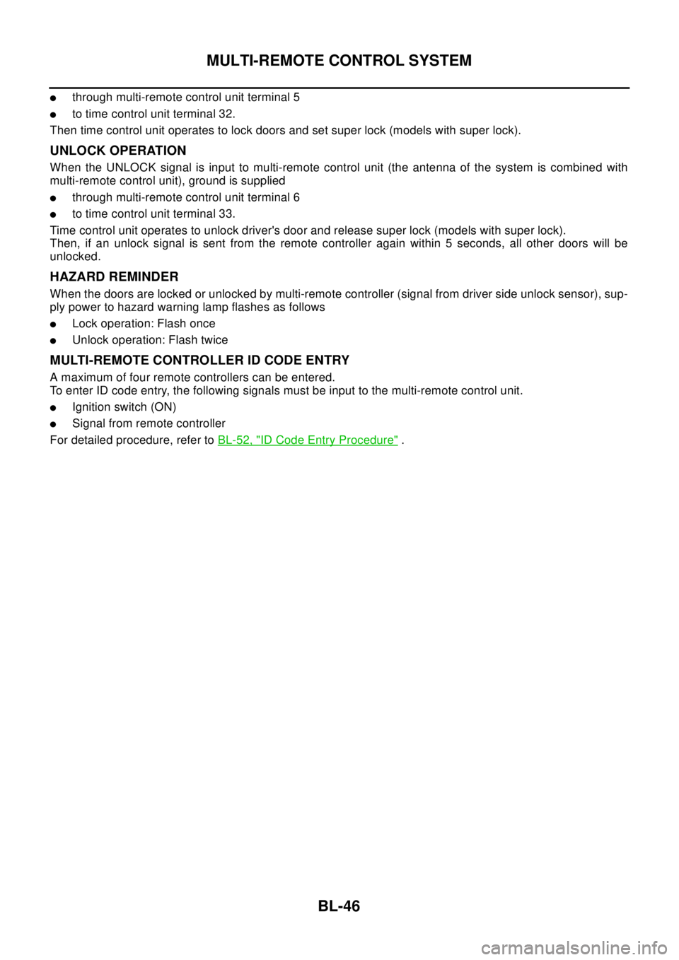
lthrough multi-remote control unit terminal 5
lto time control unit terminal 32.
Then time control unit operates to lock doors and set super lock (models with super lock).
UNLOCK OPERATION
When the UNLOCK signal is input to multi-remote control unit (the antenna of the system is combined with
multi-remote control unit), ground is supplied
lthrough multi-remote control unit terminal 6
lto time control unit terminal 33.
Time control unit operates to unlock driver's door and release super lock (models with super lock).
Then, if an unlock signal is sent from the remote controller again within 5 seconds, all other doors will be
unlocked.
HAZARD REMINDER
When the doors are locked or unlocked by multi-remote controller (signal from driver side unlock sensor), sup-
ply power to hazard warning lamp flashes as follows
lLock operation: Flash once
lUnlock operation: Flash twice
MULTI-REMOTE CONTROLLER ID CODE ENTRY
A maximum of four remote controllers can be entered.
To enter ID code entry, the following signals must be input to the multi-remote control unit.
lIgnition switch (ON)
lSignal from remote controller
For detailed procedure, refer toBL-52, "
ID Code Entry Procedure".
Page 795 of 3066

MULTI-REMOTE CONTROL SYSTEM
BL-51
C
D
E
F
G
H
J
K
L
MA
B
BL
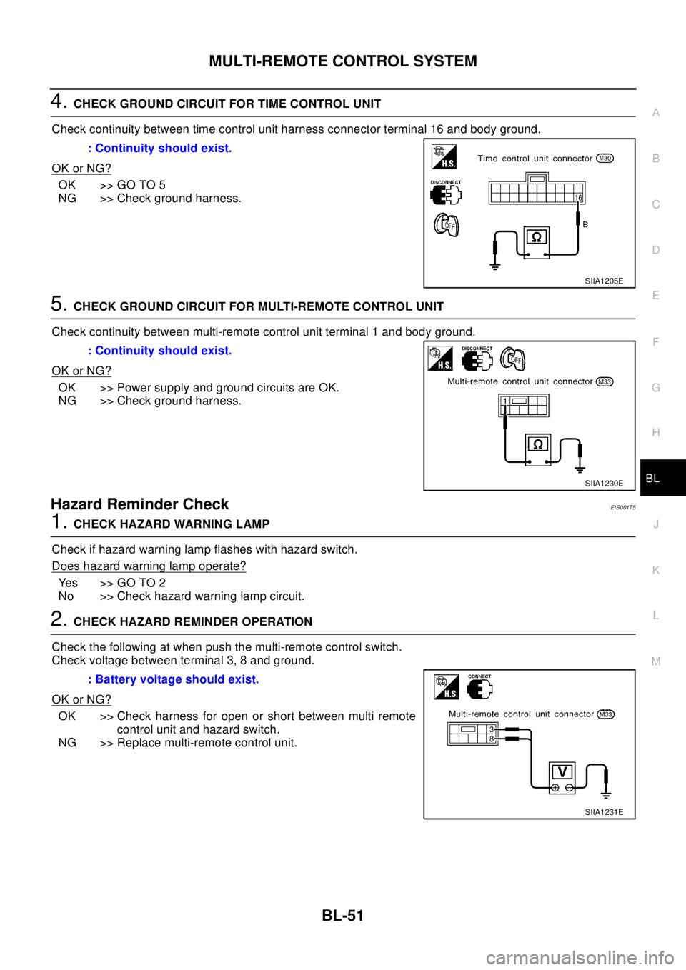
4.CHECK GROUND CIRCUIT FOR TIME CONTROL UNIT
Check continuity between time control unit harness connector terminal 16 and body ground.
OK or NG?
OK >> GO TO 5
NG >> Check ground harness.
5.CHECK GROUND CIRCUIT FOR MULTI-REMOTE CONTROL UNIT
Check continuity between multi-remote control unit terminal 1 and body ground.
OK or NG?
OK >> Power supply and ground circuits are OK.
NG >> Check ground harness.
Hazard Reminder CheckEIS0 01T 5
1.CHECK HAZARD WARNING LAMP
Check if hazard warning lamp flashes with hazard switch.
Does hazard warning lamp operate?
Yes >>GOTO2
No >> Check hazard warning lamp circuit.
2.CHECK HAZARD REMINDER OPERATION
Check the following at when push the multi-remote control switch.
Check voltage between terminal 3, 8 and ground.
OK or NG?
OK >> Check harness for open or short between multi remote
control unit and hazard switch.
NG >> Replace multi-remote control unit.: Continuity should exist.
SIIA1205E
: Continuity should exist.
SIIA1230E
: Battery voltage should exist.
SIIA1231E
Page 809 of 3066
THEFT WARNING SYSTEM
BL-65
C
D
E
F
G
H
J
K
L
MA
B
BL
THEFT WARNING SYSTEMPFP:25362
Wiring Diagram — THEFT —/PRI-WIREEIS001RM
Page 810 of 3066
BL-66
THEFT WARNING SYSTEM
LHD MODELS
TIWA0021E
Page 811 of 3066
THEFT WARNING SYSTEM
BL-67
C
D
E
F
G
H
J
K
L
MA
B
BL
TIWA0022E