2003 NISSAN X-TRAIL turn signal
[x] Cancel search: turn signalPage 3001 of 3066
ALL MODE 4X4 SYSTEM
TF-31
C
E
F
G
H
I
J
K
L
MA
B
TF
ALL MODE 4X4 SYSTEMPFP:47850
PrecautionsEDS000IV
lThis section describes ESP/TCS/ABS model.
lRefer to the BRC section for model without ESP/TCS/ABS.Refer toBRC-6, "ALL MODE 4X4 SYSTEM"
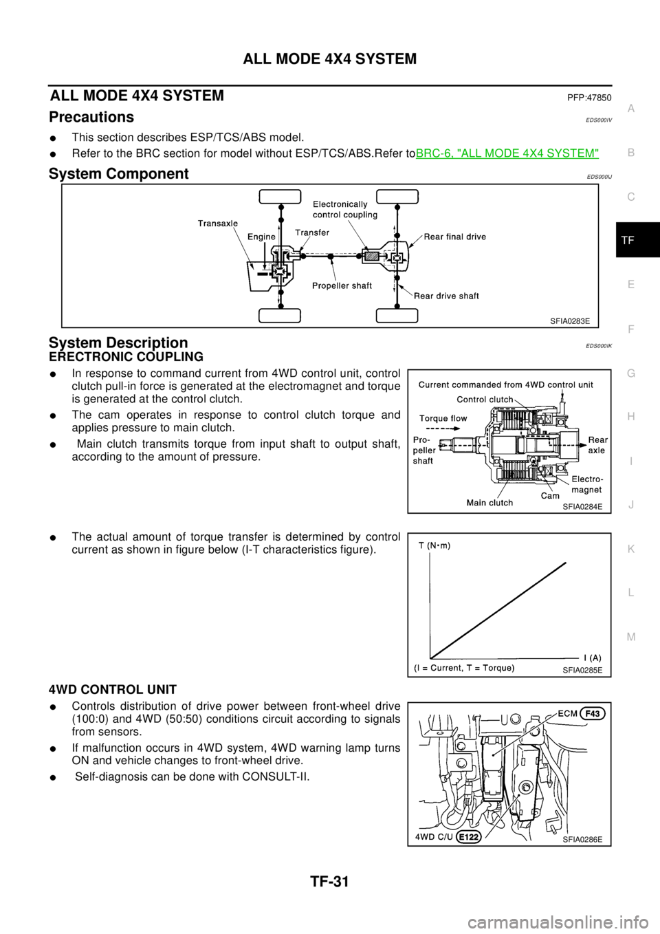
System ComponentEDS000IJ
System DescriptionEDS000IK
ERECTRONIC COUPLING
lIn response to command current from 4WD control unit, control
clutch pull-in force is generated at the electromagnet and torque
is generated at the control clutch.
lThe cam operates in response to control clutch torque and
applies pressure to main clutch.
lMain clutch transmits torque from input shaft to output shaft,
according to the amount of pressure.
lThe actual amount of torque transfer is determined by control
current as shown in figure below (I-T characteristics figure).
4WD CONTROL UNIT
lControls distribution of drive power between front-wheel drive
(100:0) and 4WD (50:50) conditions circuit according to signals
from sensors.
lIf malfunction occurs in 4WD system, 4WD warning lamp turns
ON and vehicle changes to front-wheel drive.
lSelf-diagnosis can be done with CONSULT-II.
SFIA0283E
SFIA0284E
SFIA0285E
SFIA0286E
Page 3011 of 3066
TROUBLE DIAGNOSIS
TF-41
C
E
F
G
H
I
J
K
L
MA
B
TF
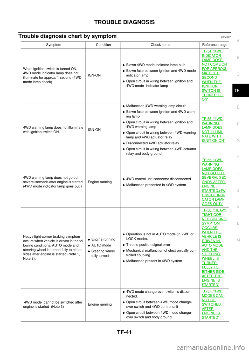
Trouble diagnosis chart by symptomEDS0 00 IT
Symptom Condition Check items Reference page
When ignition switch is turned ON,
4WD mode indicator lamp does not
illuminate for approx. 1 second (4WD
mode lamp check)IGN-ON
lBlown 4WD mode indicator lamp bulb
lBlown fuse between ignition and 4WD mode
indicator lamp
lOpen circuit in wiring between ignition and
4WD mode indicator lampTF-54, "
4WD
INDICATOR
LAMP DOSE
NOT COME ON
FOR APPROXI-
MATELY 1
SECOND
WHEN THE
IGNITION
SWITCH IS
TURNED TO
ON"
4WD warning lamp does not illuminate
with ignition switch ON.IGN-ON
lMalfunction 4WD warning lamp circuit.
lBlown fuse between ignition and 4WD warn-
ing lamp
lOpen circuit in wiring between ignition and
4WD warning lamp
lOpen circuit in wiring between 4WD warning
lamp and 4WD actuator relay
lDisconnected 4WD actuator relay
lOpen circuit in wiring between 4WD actuator
relay and body groundTF-55, "
4WD
WAR NIN G
LAMP DOES
NOT ILLUMI-
NATE WITH
IGNITION ON"
4WD warning lamp does not go out
several seconds after engine is started.
(4WD mode indicator lamp goes out.)Engine runningl4WD control unit connector disconnected
lMalfunction presented in 4WD systemTF-55, "
4WD
WAR NIN G
LAMP DOES
NOT GO OUT
SEVERAL SEC-
ONDS AFTER
ENGINE
STARTED.(4W
DMODEINDI-
CATOR LAMP
GOES OUT)"
Heavy tight-corner braking symptom
occurs when vehicle is driven in the fol-
lowing conditions: AUTO mode and
steering wheel is turned fully to either
sides after engine is started (Note 1,
Note 2).lEngine running
lAUTO mode
lSteering wheel
fully turned
lOperation is not in AUTO mode (in 2WD or
LOCK mode).
lThrottle position signal error
lMechanical malfunction of electronically con-
trolled coupling
lMalfunction present in 4WD systemTF-56, "
HEAVY
TIGHT-COR-
NER BRAKING
SYMPTOM
OCCURS
WHEN THE
VEHICLE IS
DRIVEN IN
AUTO MODE
AND THE
STEERING
WHEEL IS
TURNED
FULLY TO
EITHER SIDE
AFTER THE
ENGINE IS
STARTED"
4WD mode cannot be switched after
engine is started (Note 3)Engine running
l4WD mode change-over switch is discon-
nected.
lOpen circuit between 4WD mode change-
over switch and 4WD control unit
lOpen circuit between 4WD mode change-
over switch and body groundTF-57, "
4WD
MODES CAN-
NOT BE
SWITCHED
AFTER
ENGINE IS
STARTED"
Page 3012 of 3066
TF-42
TROUBLE DIAGNOSIS
NOTE:
1. Light tight-corner braking symptom may occur depending on driving conditions in AUTO mode. This is not
malfunction.
2. Heavy tight-corner braking symptom occurs when vehicle is driven in the following conditions: LOCK
mode, steering wheel is turned fully to either sides, and accelerator pedal was depressed.
3. When the difference of revolution speed between the front and the rear wheels is large, the 4WD mode
does not change to other mode.this is not a malfunction.
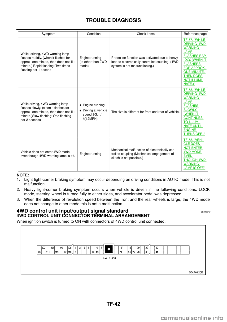
4WD control unit input/output signal standardEDS000H9
4WD CONTROL UNIT CONNECTOR TERMINAL ARRANGEMENT
When ignition switch is turned to ON with connectors of 4WD control unit connected.
While driving, 4WD warning lamp
flashes rapidly. (when it flashes for
approx. one minute, then does not illu-
minate.) Rapid flashing: Two times
flashing per 1 secondEngine running
(to other than 2WD
mode)Protection function was activated due to heavy
load to electronically controlled coupling. (4WD
system is not malfunctioning.)TF-57, "
WHILE
DRIVING, 4WD
WARN ING
LAMP
FLASHES RAP-
IDLY. (WHEN IT
FLASHERS
FOR APPROX.
ONE MINUTE,
THEN DOES
NOT ILLUMI-
NATE.)"
While driving, 4WD warning lamp
flashes slowly. (when it flashes for
approx. one minute, then does not illu-
minate.)Slow flashing: One flashing
per 2 secondslEngine running
lDriving at vehicle
speed 20km/
h(12MPH)Tire size is different for front and rear of vehicle.TF-58, "
WHILE
DRIVING, 4WD
WARN ING
LAMP
FLASHES
SLOWLY.
(WHEN IT
CONTINUES
TO ILLUMI-
NATE UNTIL
ENGINE
TURNS OFF.)"
Vehicle does not enter 4WD mode
even though 4WD warning lamp is off.Engine runningMechanical malfunction of electronically con-
trolled coupling (Mechanical engagement of
clutch is not possible.)TF-58, "
VEHI-
CLE DOES
NOT ENTER
4WD MODE
EVEN
THOUGH 4WD
WARN ING
LAMP IS OFF."
Symptom Condition Check items Reference page
SDIA0120E
Page 3016 of 3066

TF-46
TROUBLE DIAGNOSIS
CAUTION:
If memory cannot be erased, proceed to 5.
9. Drive at approx. 30 km/h (19MPH) for approx. 1 minute. Be sure 4WD warning lamp is OFF.
Display item list
CAUTION:
lIf "ALL MODE 4WD" is not displayed on system selection screen, check the following: 4WD actua-
tor and control unit, data link connector harness, and No. of CONSULT-II program card
lWhen several systems including CAN communication system indicates troubles, perform trouble
diagnosis of the CAN communication primarily.
DATA MONITOR
lFor details of data monitor function, refer to CONSULT -II Operation Manual.
Operation procedure
1. Turn the ignition switch to OFF.
2. Connect CONSULT-II connector to data link connector on vehicle.
3. Turn ignition switch ON.
4. Touch "START" on the display.
5. Touch "ALL MODE 4WD" on the display.
CAUTION:
"ALL MODE 4WD" may not be displayed on the system selection screen in the following case:
When "START" was touched just after engine is started or ignition switch is turned to ON. In this
case, repeat procedure from step 2.
6. Touch "DATA MONITOR".
7. Return to monitor item selection screen. Touch any of "ECU INPUT SIGNALS," "MAIN SIGNALS," "CAN
DIG SUPPORT MNTR" or "SELECTION FROM MENU".
Refer to the following "Data monitor item chart".
Item Malfunction detecting condition Check harness
DECEL G-SENSOR Longitudinal G-sensor output voltage is outside specification.
G-sensor harness
G-SENSOR VOLTAGEPower voltage of longitudinal G-sensor remains abnormally high
or low for a certain period of time.
ETS SOLENOID
(4WD solenoid valve) (Open)4WD solenoid valve control terminal is not supplied with proper
voltage due to open circuit in 4WD solenoid valve.
4WD actuator relay,
solenoid and harness ETS SOLENOID
(4WD solenoid valve) (Short)4WD solenoid valve control terminal is not supplied with proper
voltage due to short circuit in 4WD solenoid valve.
ETS SOLENOID
(4WD solenoid valve)
(CURRENT FAILURE)Current supplied to 4WD solenoid valve is abnormally high or
low compared with the specification.
CONTROL UNIT Processing function of 4WD control unit is malfunctioning.4WD control unit, power
and ground circuits
DECEL G-SEN MONI Output voltage of longitudinal G-sensor is outside specification. G-sensor harness
DECEL G-SEN IN Input voltage of longitudinal G-sensor is outside specification. G-sensor harness
3 V POWER SUPLY CHECK 4WD control unit internal 3V power supply is malfunctioning.Control unit power sup-
ply circuit
4WD A/R CHECK 4WD actuator relay turned on while it is controlled OFF.
4WD actuator relay,
4WD solenoid and har-
ness. 4WD SOL/V CHECK4WD solenoid not supplied with proper voltage
due to open circuit in 4WD solenoid valve.
CAN COMM
lCAN communication function of 4WD control unit is malfunc-
tioning.
lCAN communication function of EPS control unit is malfunc-
tioning.Control unit power sup-
ply circuit
ABS 4WD COMMWheel speed sensor system of ESP/TCS/ABS control unit is
malfunctioning.ESP/TCS/ABS control
unit and harness
Page 3023 of 3066
TROUBLE DIAGNOSIS
TF-53
C
E
F
G
H
I
J
K
L
MA
B
TF
CAN COMMUNICATION SYSTEM
Checking procedure
1.INSPECTION START
Check the self-diagnosis results with CONSULT-II.
Status of "CAN communications" is OK?
YES >> After printing out self-diagnosis results, go to 2.
NO >> Checking is completed.
2.SYMPTOM CHECK
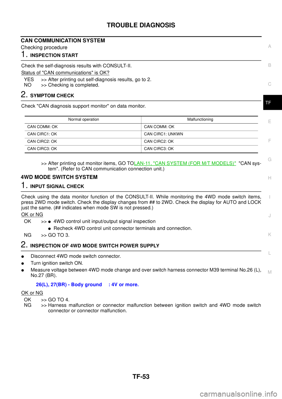
Check "CAN diagnosis support monitor" on data monitor.
>> After printing out monitor items, GO TOLAN-11, "
CAN SYSTEM (FOR M/T MODELS)""CAN sys-
tem". (Refer to CAN communication connection unit.)
4WD MODE SWITCH SYSTEM
1.INPUT SIGNAL CHECK
Check using the data monitor function of the CONSULT-II. While monitoring the 4WD mode switch items,
press 2WD mode switch. Check the display changes from ## to 2WD. Check the display for AUTO and LOCK
just the same. (## indicates when mode SW is not pressed.)
OK or NG
OK >>l4WD control unit input/output signal inspection
lRecheck 4WD control unit connector terminals and connection.
NG >> GO TO 3.
2.INSPECTION OF 4WD MODE SWITCH POWER SUPPLY
lDisconnect 4WD mode switch connector.
lTurn ignition switch ON.
lMeasure voltage between 4WD mode change and over switch harness connector M39 terminal No.26 (L),
No.27 (BR).
OK or NG
OK >> GO TO 4.
NG >> Harness malfunction or connector malfunction between ignition switch and 4WD mode switch
connector or connector malfunction.
Normal operation Malfunctioning
CAN COMM: OK CAN COMM: OK
CAN CIRC1: OK CAN CIRC1: UNKWN
CAN CIRC2: OK CAN CIRC2: OK
CAN CIRC3: OK CAN CIRC3: OK
26(L), 27(BR) - Body ground : 4V or more.
Page 3024 of 3066
TF-54
TROUBLE DIAGNOSIS
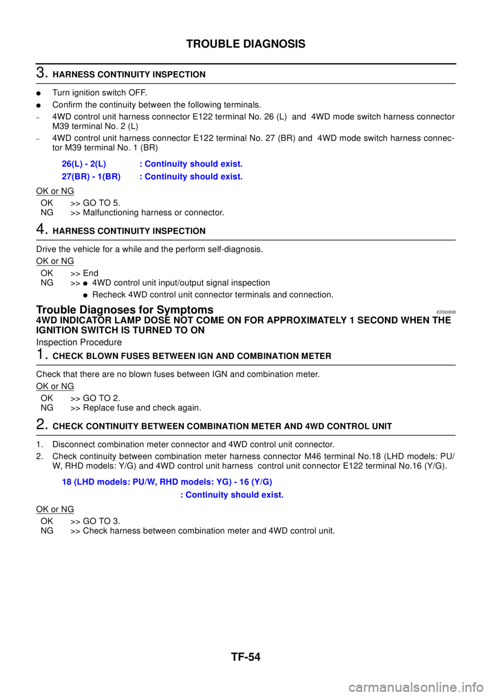
3.HARNESS CONTINUITY INSPECTION
lTurn ignition switch OFF.
lConfirm the continuity between the following terminals.
–4WD control unit harness connector E122 terminal No. 26 (L) and 4WD mode switch harness connector
M39 terminal No. 2 (L)
–4WD control unit harness connector E122 terminal No. 27 (BR) and 4WD mode switch harness connec-
tor M39 terminal No. 1 (BR)
OK or NG
OK >> GO TO 5.
NG >> Malfunctioning harness or connector.
4.HARNESS CONTINUITY INSPECTION
Drive the vehicle for a while and the perform self-diagnosis.
OK or NG
OK >> End
NG >>
l4WD control unit input/output signal inspection
lRecheck 4WD control unit connector terminals and connection.
Trouble Diagnoses for SymptomsEDS000IS
4WD INDICATOR LAMP DOSE NOT COME ON FOR APPROXIMATELY 1 SECOND WHEN THE
IGNITION SWITCH IS TURNED TO ON
Inspection Procedure
1.CHECK BLOWN FUSES BETWEEN IGN AND COMBINATION METER
Check that there are no blown fuses between IGN and combination meter.
OK or NG
OK >> GO TO 2.
NG >> Replace fuse and check again.
2.CHECK CONTINUITY BETWEEN COMBINATION METER AND 4WD CONTROL UNIT
1. Disconnect combination meter connector and 4WD control unit connector.
2. Check continuity between combination meter harness connector M46 terminal No.18 (LHD models: PU/
W, RHD models: Y/G) and 4WD control unit harness control unit connector E122 terminal No.16 (Y/G).
OK or NG
OK >> GO TO 3.
NG >> Check harness between combination meter and 4WD control unit.26(L) - 2(L) : Continuity should exist.
27(BR) - 1(BR) : Continuity should exist.
18 (LHD models: PU/W, RHD models: YG) - 16 (Y/G)
: Continuity should exist.
Page 3045 of 3066
FRONT WIPER AND WASHER SYSTEM
WW-7
C
D
E
F
G
H
I
J
L
MA
B
WW
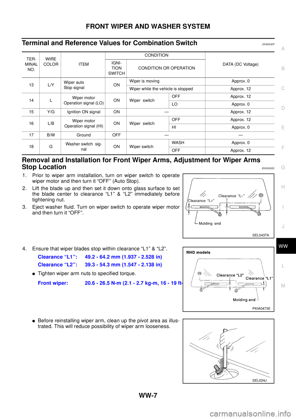
Terminal and Reference Values for Combination SwitchEKS0032P
Removal and Installation for Front Wiper Arms, Adjustment for Wiper Arms
Stop Location
EKS0032Q
1. Prior to wiper arm installation, turn on wiper switch to operate
wiper motor and then turn it “OFF” (Auto Stop).
2. Lift the blade up and then set it down onto glass surface to set
the blade center to clearance “L1” & “L2” immediately before
tightening nut.
3. Eject washer fluid. Turn on wiper switch to operate wiper motor
and then turn it “OFF”.
4. Ensure that wiper blades stop within clearance “L1” & “L2”.
lTighten wiper arm nuts to specified torque.
lBefore reinstalling wiper arm, clean up the pivot area as illus-
trated. This will reduce possibility of wiper arm looseness.
TER-
MINAL
NO.WIRE
COLOR ITEMCONDITION
DATA (DC Voltage) IGNI-
TION
SWITCHCONDITION OR OPERATION
13 L/YWiper auto
Stop signalONWiper is moving Approx. 0
Wiper while the vehicle is stopped Approx. 12
14 LWiper motor
Operation signal (LO)ON Wiper switchOFF Approx. 12
LO Approx. 0
15 Y/G Ignition ON signal ON — Approx. 12
16 L/BWiper motor
Operation signal (HI)ON Wiper switchOFF Approx. 12
HI Approx. 0
17 B/W Ground OFF — —
18 GWasher switch sig-
nalON Wiper switchWASH Approx. 0
OFF Approx. 12
SEL543TA
Clearance “L1”: 49.2 - 64.2 mm (1.937 - 2.528 in)
Clearance “L2”: 39.3 - 54.3 mm (1.547 - 2.138 in)
Front wiper: 20.6 - 26.5 N-m (2.1 - 2.7 kg-m, 16 - 19 ft-lb)
PKIA0473E
SEL024J
Page 3053 of 3066
REAR WIPER AND WASHER SYSTEM
WW-15
C
D
E
F
G
H
I
J
L
MA
B
WW
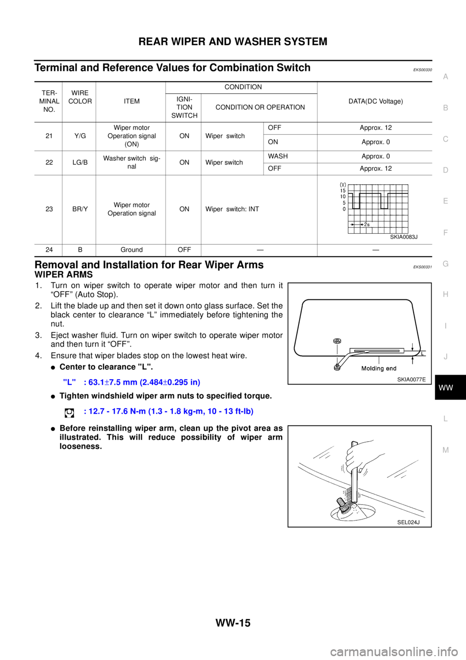
Terminal and Reference Values for Combination SwitchEKS00330
Removal and Installation for Rear Wiper ArmsEKS00331
WIPER ARMS
1. Turn on wiper switch to operate wiper motor and then turn it
“OFF” (Auto Stop).
2. Lift the blade up and then set it down onto glass surface. Set the
black center to clearance “L” immediately before tightening the
nut.
3. Eject washer fluid. Turn on wiper switch to operate wiper motor
and then turn it “OFF”.
4. Ensure that wiper blades stop on the lowest heat wire.
lCenter to clearance "L".
lTighten windshield wiper arm nuts to specified torque.
lBefore reinstalling wiper arm, clean up the pivot area as
illustrated. This will reduce possibility of wiper arm
looseness.
TER-
MINAL
NO.WIRE
COLOR ITEMCONDITION
DATA(DC Voltage) IGNI-
TION
SWITCHCONDITION OR OPERATION
21 Y/GWiper motor
Operation signal
(ON)ON Wiper switchOFF Approx. 12
ON Approx. 0
22 LG/BWasher switch sig-
nalON Wiper switchWASH Approx. 0
OFF Approx. 12
23 BR/YWiper motor
Operation signalON Wiper switch: INT
24 B Ground OFF — —
SKIA0083J
"L" : 63.1±7.5 mm (2.484±0.295 in)
: 12.7 - 17.6 N-m (1.3 - 1.8 kg-m, 10 - 13 ft-lb)SKIA0077E
SEL024J