2003 NISSAN X-TRAIL turn signal
[x] Cancel search: turn signalPage 2422 of 3066
LT-24
LIGHTING AND TURN SIGNAL SWITCH
LIGHTING AND TURN SIGNAL SWITCH
PFP:25540
Removal and InstallationEKS0034F
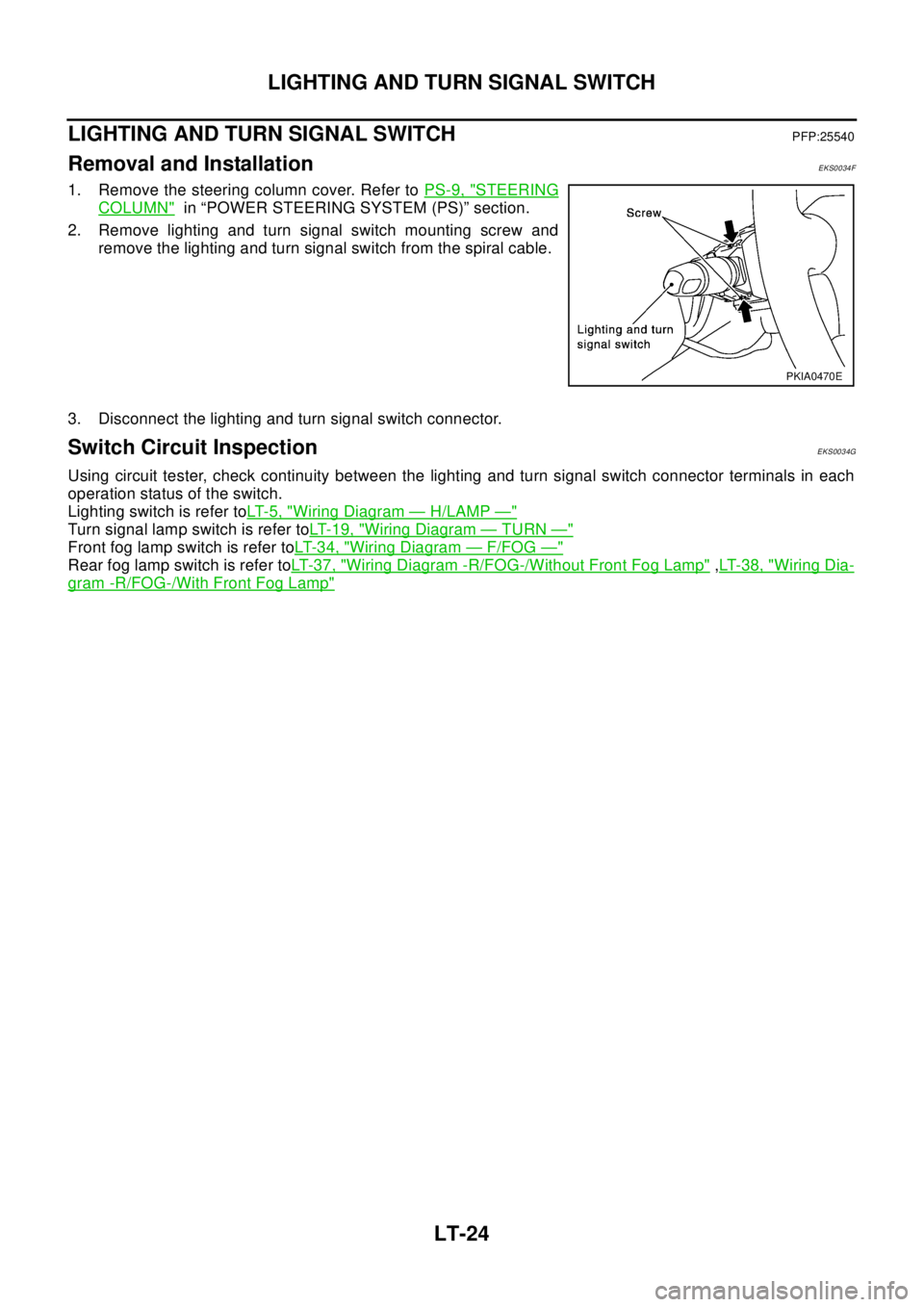
1. Remove the steering column cover. Refer toPS-9, "STEERING
COLUMN"in “POWER STEERING SYSTEM (PS)” section.
2. Remove lighting and turn signal switch mounting screw and
remove the lighting and turn signal switch from the spiral cable.
3. Disconnect the lighting and turn signal switch connector.
Switch Circuit InspectionEKS0034G
Using circuit tester, check continuity between the lighting and turn signal switch connector terminals in each
operation status of the switch.
Lighting switch is refer toLT- 5 , "
Wiring Diagram—H/LAMP—"
Turn signal lamp switch is refer toLT-19, "Wiring Diagram—TURN—"
Front fog lamp switch is refer toLT-3 4, "Wiring Diagram—F/FOG—"
Rear fog lamp switch is refer toLT- 3 7 , "Wiring Diagram -R/FOG-/Without Front Fog Lamp",LT-38, "Wiring Dia-
gram -R/FOG-/With Front Fog Lamp"
PKIA0470E
Page 2441 of 3066
REAR COMBINATION LAMP
LT-43
C
D
E
F
G
H
I
J
L
MA
B
LT
Bulb ReplacementEKS00164
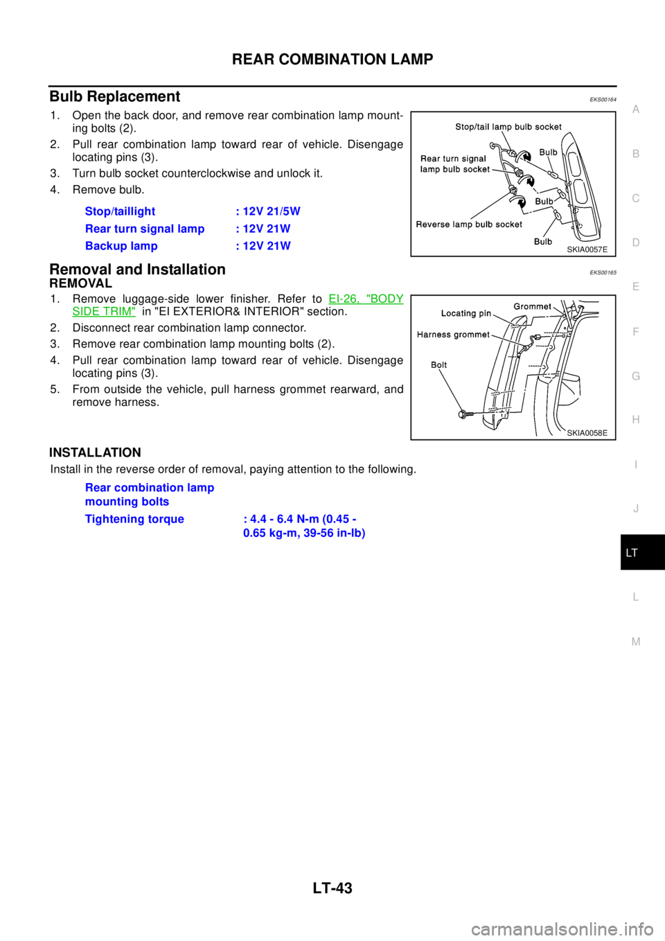
1. Open the back door, and remove rear combination lamp mount-
ing bolts (2).
2. Pull rear combination lamp toward rear of vehicle. Disengage
locating pins (3).
3. Turn bulb socket counterclockwise and unlock it.
4. Remove bulb.
Removal and InstallationEKS00165
REMOVAL
1. Remove luggage-side lower finisher. Refer toEI-26, "BODY
SIDE TRIM"in "EI EXTERIOR& INTERIOR" section.
2. Disconnect rear combination lamp connector.
3. Remove rear combination lamp mounting bolts (2).
4. Pull rear combination lamp toward rear of vehicle. Disengage
locating pins (3).
5. From outside the vehicle, pull harness grommet rearward, and
remove harness.
INSTALLATION
Install in the reverse order of removal, paying attention to the following.Stop/taillight : 12V 21/5W
Rear turn signal lamp : 12V 21W
Backup lamp : 12V 21W
SKIA0057E
SKIA0058E
Rear combination lamp
mounting bolts
Tightening torque : 4.4 - 6.4 N-m (0.45 -
0.65 kg-m, 39-56 in-lb)
Page 2442 of 3066
LT-44
COMBINATION SWITCH
COMBINATION SWITCH
PFP:25567
Removal and InstallationEKS001V6
Refer toSRS-31, "SPIRAL CABLE"in "SUPPLEMENTAL RESTRAINT SYSTEM (SRS)" section for details.
Switch Circuit InspectionEKS001V7
Refer toLT- 2 4 , "Switch Circuit Inspection"in "LIGHTING AND TURN SIGNAL SWITCH" section, andWW-7,
"Terminal and Reference Values for Combination Switch",WW-15, "Terminal and Reference Values for Com-
bination Switch"in“ WW Wiper/Washer Horn” section for details.
Page 2454 of 3066

LT-56
INTERIOR ROOM LAMP
lunlock signal is supplied from driver's door unlock sensor while all doors are closed and key is out of igni-
tion key cylinder
lkey is removed from ignition key cylinder while all doors are closed
ldriver's door is opened and then closed while key is out of the iginition key cylinder. (However, if the
driver's door is closed with the key inserted in the ignition key cylinder after the driver's door is opened
with the key removed, the timer is operated.)
The timer is canceled when:
ldriver's door is locked,
ldriver's door is opened, or
lignition switch is turned ON.
ON-OFF CONTROL
When the driver side door, front passenger door, rear LH or RH door is opened, the interior room lamp turns
on while the interior room lamp switch is in the “DOOR” position.
Page 2465 of 3066
BULB SPECIFICATIONS
LT-67
C
D
E
F
G
H
I
J
L
MA
B
LT
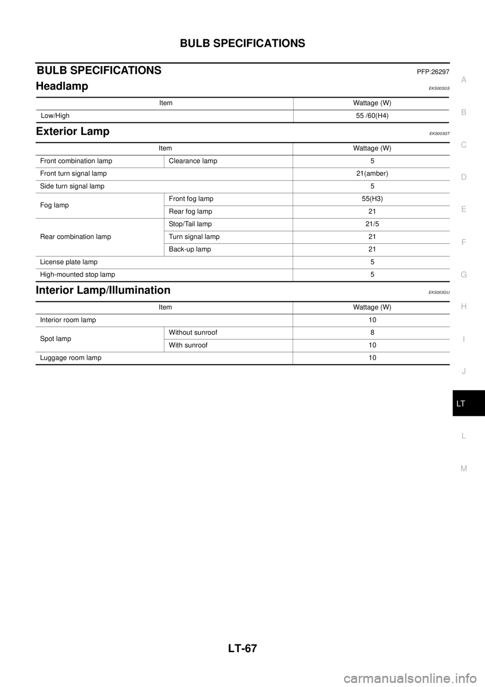
BULB SPECIFICATIONSPFP:26297
HeadlampEKS003GS
Exterior LampEKS003GT
Interior Lamp/IlluminationEKS003GU
Item Wattage (W)
Low/High55 /60(H4)
Item Wattage (W)
Front combination lamp Clearance lamp 5
Front turn signal lamp21(amber)
Side turn signal lamp5
Fog lampFront fog lamp 55(H3)
Rear fog lamp 21
Rear combination lampStop/Tail lamp 21/5
Turn signal lamp 21
Back-up lamp 21
License plate lamp5
High-mounted stop lamp5
Item Wattage (W)
Interior room lamp10
Spot lampWithout sunroof 8
With sunroof 10
Luggage room lamp10
Page 2498 of 3066
MA-6
GENERAL MAINTENANCE
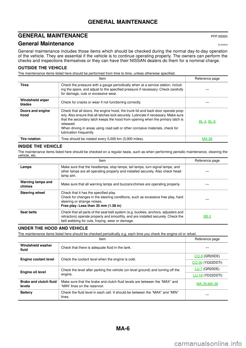
GENERAL MAINTENANCE
PFP:00000
General MaintenanceELS000AL
General maintenance includes those items which should be checked during the normal day-to-day operation
of the vehicle. They are essential if the vehicle is to continue operating properly. The owners can perform the
checks and inspections themselves or they can have their NISSAN dealers do them for a nominal charge.
OUTSIDE THE VEHICLE
The maintenance items listed here should be performed from time to time, unless otherwise specified.
INSIDE THE VEHICLE
The maintenance items listed here should be checked on a regular basis, such as when performing periodic maintenance, cleaning the
vehicle, etc.
UNDER THE HOOD AND VEHICLE
The maintenance items listed here should be checked periodically e.g. each time you check the engine oil or refuel.Item Reference page
TiresCheck the pressure with a gauge periodically when at a service station, includ-
ing the spare, and adjust to the specified pressure if necessary. Check carefully
for damage, cuts or excessive wear.—
Windshield wiper
bladesCheck for cracks or wear if not functioning correctly. —
Doors and engine
hoodCheck that all doors, the engine hood, the trunk lid and back door operate prop-
erly. Also ensure that all latches lock securely. Lubricate if necessary. Make sure
that the secondary latch keeps the hood from opening when the primary latch is
released.
When driving in areas using road salt or other corrosive materials, check for
lubrication frequently.BL-4
,BL-8
Tire rotationTires should be rotated every 5,000 km (3,000 miles).MA-38
Item Reference page
LampsMake sure that the headlamps, stop lamps, tail lamps, turn signal lamps, and
other lamps are all operating properly and installed securely. Also check head-
lamp aim.—
Warning lamps and
chimesMake sure that all warning lamps and buzzers/chimes are operating properly. —
Steering wheelCheck that it has the specified play.
Check for changes in the steering conditions, such as excessive free play, hard
steering or strange noises.
Free play: Less than 35 mm (1.38 in)—
Seat beltsCheck that all parts of the seat belt system (e.g. buckles, anchors, adjusters and
retractors) operate properly and smoothly, and are installed securely. Check the
belt webbing for cuts, fraying, wear or damage.SB-3
Item Reference page
Windshield washer
fluidCheck that there is adequate fluid in the tank. —
Engine coolant levelCheck the coolant level when the engine is cold.CO-9
(QR20DE)
CO-30
(YD22DDTi)
Engine oil levelCheck the level after parking the vehicle (on level ground) and turning off the
engine.LU-7
(QR20DE)
LU-18
(YD22DDTi)
Brake and clutch fluid
levelsMake sure that the brake and clutch fluid levels are between the “MAX” and
“MIN” lines on the reservoir.MA-35
,MA-38
BatteryCheck the fluid level in each cell. It should be between the “MAX” and “MIN”
lines.—
Page 2739 of 3066
HARNESS
PG-63
C
D
E
F
G
H
I
J
L
MA
B
PG
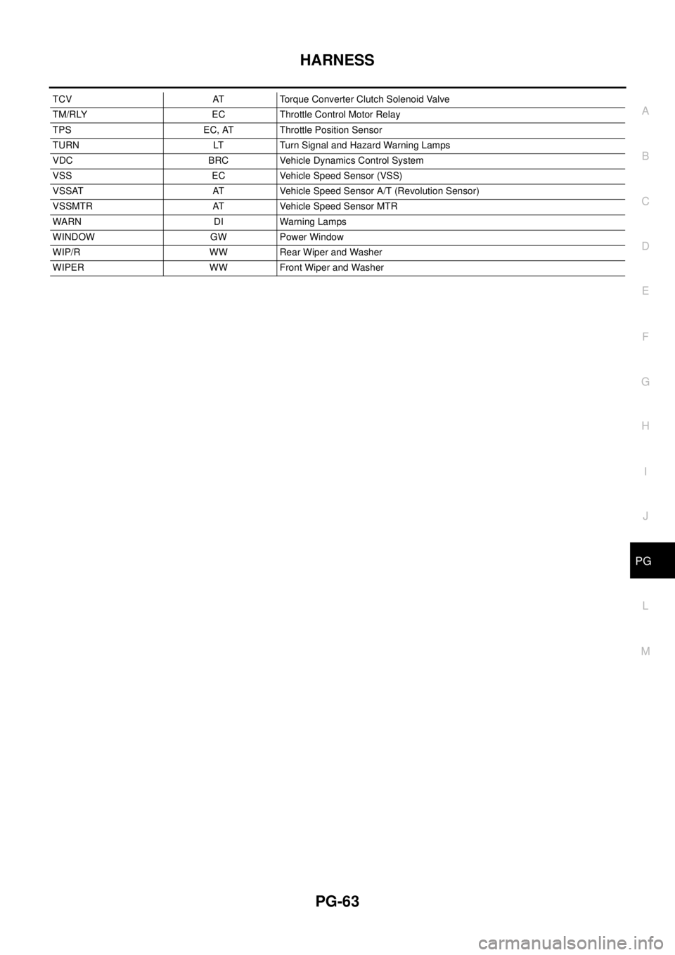
TCV AT Torque Converter Clutch Solenoid Valve
TM/RLY EC Throttle Control Motor Relay
TPS EC, AT Throttle Position Sensor
TURN LT Turn Signal and Hazard Warning Lamps
VDC BRC Vehicle Dynamics Control System
VSS EC Vehicle Speed Sensor (VSS)
VSSAT AT Vehicle Speed Sensor A/T (Revolution Sensor)
VSSMTR AT Vehicle Speed Sensor MTR
WARN D I Warning Lam ps
WINDOW GW Power Window
WIP/R WW Rear Wiper and Washer
WIPER WW Front Wiper and Washer
Page 2971 of 3066
TF-1
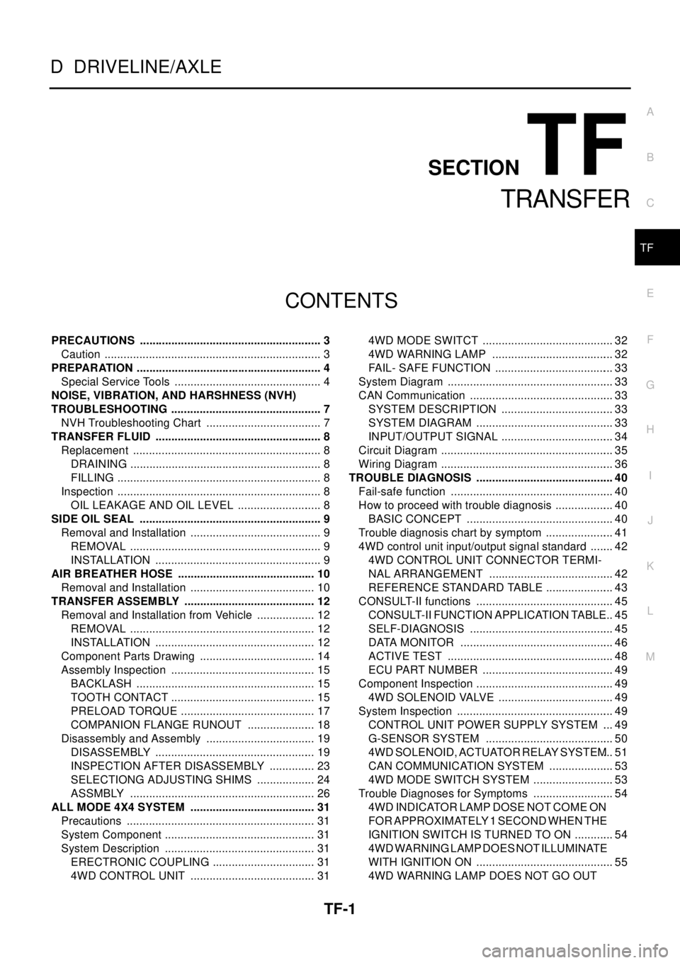
TRANSFER
D DRIVELINE/AXLE
CONTENTS
C
E
F
G
H
I
J
K
L
M
SECTION
A
B
TF
TRANSFER
PRECAUTIONS .......................................................... 3
Caution ..................................................................... 3
PREPARATION ........................................................... 4
Special Service Tools ............................................... 4
NOISE, VIBRATION, AND HARSHNESS (NVH)
TROUBLESHOOTING ................................................ 7
NVH Troubleshooting Chart ..................................... 7
TRANSFER FLUID ..................................................... 8
Replacement ............................................................ 8
DRAINING ............................................................. 8
FILLING ................................................................. 8
Inspection ................................................................. 8
OIL LEAKAGE AND OIL LEVEL ........................... 8
SIDE OIL SEAL .......................................................... 9
Removal and Installation .......................................... 9
REMOVAL ............................................................. 9
INSTALLATION ..................................................... 9
AIR BREATHER HOSE ............................................ 10
Removal and Installation ........................................ 10
TRANSFER ASSEMBLY .......................................... 12
Removal and Installation from Vehicle ................... 12
REMOVAL ........................................................... 12
INSTALLATION ................................................... 12
Component Parts Drawing ..................................... 14
Assembly Inspection .............................................. 15
BACKLASH ......................................................... 15
TOOTH CONTACT .............................................. 15
PRELOAD TORQUE ........................................... 17
COMPANION FLANGE RUNOUT ...................... 18
Disassembly and Assembly ................................... 19
DISASSEMBLY ................................................... 19
INSPECTION AFTER DISASSEMBLY ............... 23
SELECTIONG ADJUSTING SHIMS ................... 24
ASSMBLY ........................................................... 26
ALL MODE 4X4 SYSTEM ........................................ 31
Precautions ............................................................ 31
System Component ................................................ 31
System Description ................................................ 31
ERECTRONIC COUPLING ................................. 31
4WD CONTROL UNIT ........................................ 314WD MODE SWITCT .......................................... 32
4WD WARNING LAMP ....................................... 32
FAIL- SAFE FUNCTION ...................................... 33
System Diagram ..................................................... 33
CAN Communication .............................................. 33
SYSTEM DESCRIPTION .................................... 33
SYSTEM DIAGRAM ............................................ 33
INPUT/OUTPUT SIGNAL .................................... 34
Circuit Diagram ....................................................... 35
Wiring Diagram ....................................................... 36
TROUBLE DIAGNOSIS ............................................ 40
Fail-safe function .................................................... 40
How to proceed with trouble diagnosis ................... 40
BASIC CONCEPT ............................................... 40
Trouble diagnosis chart by symptom ...................... 41
4WD control unit input/output signal standard ........ 42
4WD CONTROL UNIT CONNECTOR TERMI-
NAL ARRANGEMENT ........................................ 42
REFERENCE STANDARD TABLE ...................... 43
CONSULT-II functions ............................................ 45
CONSULT-II FUNCTION APPLICATION TABLE... 45
SELF-DIAGNOSIS .............................................. 45
DATA MONITOR ................................................. 46
ACTIVE TEST ..................................................... 48
ECU PART NUMBER .......................................... 49
Component Inspection ............................................ 49
4WD SOLENOID VALVE ..................................... 49
System Inspection .................................................. 49
CONTROL UNIT POWER SUPPLY SYSTEM .... 49
G-SENSOR SYSTEM ......................................... 50
4WD SOLENOID, ACTUATOR RELAY SYSTEM... 51
CAN COMMUNICATION SYSTEM ..................... 53
4WD MODE SWITCH SYSTEM .......................... 53
Trouble Diagnoses for Symptoms .......................... 54
4WD INDICATOR LAMP DOSE NOT COME ON
FORAPPROXIMATELY1SECONDWHENTHE
IGNITION SWITCH IS TURNED TO ON ............. 54
4WD WARNING LAMP DOES NOT ILLUMINATE
WITH IGNITION ON ............................................ 55
4WD WARNING LAMP DOES NOT GO OUT