2003 NISSAN X-TRAIL drain bolt
[x] Cancel search: drain boltPage 567 of 3066
![NISSAN X-TRAIL 2003 Electronic Repair Manual ASSEMBLY
AT-561
[ALL]
D
E
F
G
H
I
J
K
L
MA
B
AT
f. Tighten boltsI,Xandl.
Bolt length, number and location:
18. Install oil pan.
a. Attach a magnet to oil pan.
b. Install new oil pan gasket on transmis NISSAN X-TRAIL 2003 Electronic Repair Manual ASSEMBLY
AT-561
[ALL]
D
E
F
G
H
I
J
K
L
MA
B
AT
f. Tighten boltsI,Xandl.
Bolt length, number and location:
18. Install oil pan.
a. Attach a magnet to oil pan.
b. Install new oil pan gasket on transmis](/manual-img/5/57402/w960_57402-566.png)
ASSEMBLY
AT-561
[ALL]
D
E
F
G
H
I
J
K
L
MA
B
AT
f. Tighten boltsI,Xandl.
Bolt length, number and location:
18. Install oil pan.
a. Attach a magnet to oil pan.
b. Install new oil pan gasket on transmission case.
c. Install oil pan on transmission case.
lAlways replace oil pan bolts as they are self-sealing
bolts.
lTighten four bolts in a criss-cross pattern to prevent dis-
location of gasket.
d. Tighten oil pan bolts and drain plug to the specified torque.
Refer toAT- 4 6 1 , "
OVERHAUL".
19. Install park/neutral position (PNP) switch.
a. Set manual shaft in P position.
b. Temporarily install park/neutral position (PNP) switch on manual
shaft.
c. Move selector lever to N position.
BoltIXl
Bolt length “ ” mm (in)40 (1.57) 33 (1.30)43.5
(1.713)
Number of bolts 5 6 2
SAT004F
SAT003F
SAT033J
Page 568 of 3066
![NISSAN X-TRAIL 2003 Electronic Repair Manual AT-562
[ALL]
ASSEMBLY
d. Use a 4 mm (0.16 in) pin for this adjustment.
i. Insert the pin straight into the manual shaft adjustment hole.
ii. Rotate park/neutral position (PNP) switch until the pin can NISSAN X-TRAIL 2003 Electronic Repair Manual AT-562
[ALL]
ASSEMBLY
d. Use a 4 mm (0.16 in) pin for this adjustment.
i. Insert the pin straight into the manual shaft adjustment hole.
ii. Rotate park/neutral position (PNP) switch until the pin can](/manual-img/5/57402/w960_57402-567.png)
AT-562
[ALL]
ASSEMBLY
d. Use a 4 mm (0.16 in) pin for this adjustment.
i. Insert the pin straight into the manual shaft adjustment hole.
ii. Rotate park/neutral position (PNP) switch until the pin can also
be inserted straight into hole in park/neutral position (PNP)
switch.
e. Tighten park/neutral position (PNP) switch fixing bolts. Refer to
AT-461, "
OVERHAUL".
f. Remove pin from adjustment hole after adjusting park/neutral
position (PNP) switch.
20. Install A/T fluid charging pipe and fluid cooler tube to transmis-
sion case. Tighten A/T fluid charging pipe and fluid cooler tube
bolts to the specified torque. Refer toAT-461, "
OVERHAUL".
21. Install torque converter.
a. Pour ATF into torque converter.
lApproximately 1 liter (1-1/8 US qt, 7/8 Imp qt) of fluid is
required for a new torque converter.
lWhen reusing old torque converter, add the same amount
of fluid as was drained.
b. Install torque converter while aligning notches of torque con-
verter with notches of oil pump.
c. Measure distance “A” to check that torque converter is in proper
position.
AAT469A
SAT768J
SAT428DA
SAT429D
Distance A :
Refer toAT-563, "
SERVICE DATA AND SPECIFICA-
TIONS (SDS)".
SAT430D
Page 845 of 3066
BRAKE PIPING AND HOSE
BR-11
C
D
E
G
H
I
J
K
L
MA
B
BR
BRAKE PIPING AND HOSEPFP:46210
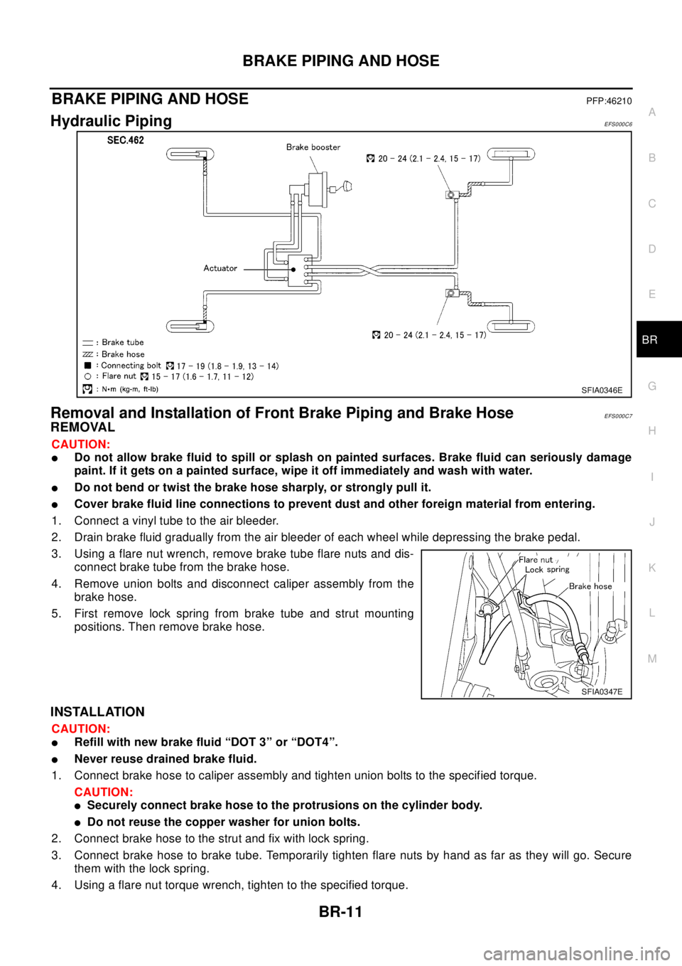
Hydraulic PipingEFS000C6
Removal and Installation of Front Brake Piping and Brake HoseEFS000C7
REMOVAL
CAUTION:
lDo not allow brake fluid to spill or splash on painted surfaces. Brake fluid can seriously damage
paint. If it gets on a painted surface, wipe it off immediately and wash with water.
lDo not bend or twist the brake hose sharply, or strongly pull it.
lCover brake fluid line connections to prevent dust and other foreign material from entering.
1. Connect a vinyl tube to the air bleeder.
2. Drain brake fluid gradually from the air bleeder of each wheel while depressing the brake pedal.
3. Using a flare nut wrench, remove brake tube flare nuts and dis-
connect brake tube from the brake hose.
4. Remove union bolts and disconnect caliper assembly from the
brake hose.
5. First remove lock spring from brake tube and strut mounting
positions. Then remove brake hose.
INSTALLATION
CAUTION:
lRefill with new brake fluid “DOT 3” or “DOT4”.
lNever reuse drained brake fluid.
1. Connect brake hose to caliper assembly and tighten union bolts to the specified torque.
CAUTION:
lSecurely connect brake hose to the protrusions on the cylinder body.
lDo not reuse the copper washer for union bolts.
2. Connect brake hose to the strut and fix with lock spring.
3. Connect brake hose to brake tube. Temporarily tighten flare nuts by hand as far as they will go. Secure
them with the lock spring.
4. Using a flare nut torque wrench, tighten to the specified torque.
SFIA0346E
SFIA0347E
Page 846 of 3066
BR-12
BRAKE PIPING AND HOSE
5. Refill brake fluid until new brake fluid comes out of each air bleeder.
6. Afterwards, bleed air.
Removal and Installation of Rear Brake Piping and Brake HoseEFS000C8
REMOVAL
CAUTION:
lDo not allow brake fluid to spill or splash on painted surfaces. Brake fluid can seriously damage
paint. If it gets on a painted surface, wipe it off immediately and wash with water.
lDo not bend or twist the brake hose sharply, or strongly pull it.
lCover brake fluid line connections to prevent dust and other foreign material from entering.
1. Connect a vinyl tube to the air bleeder.
2. Drain brake fluid gradually from the air bleeder of each wheel while depressing the brake pedal.
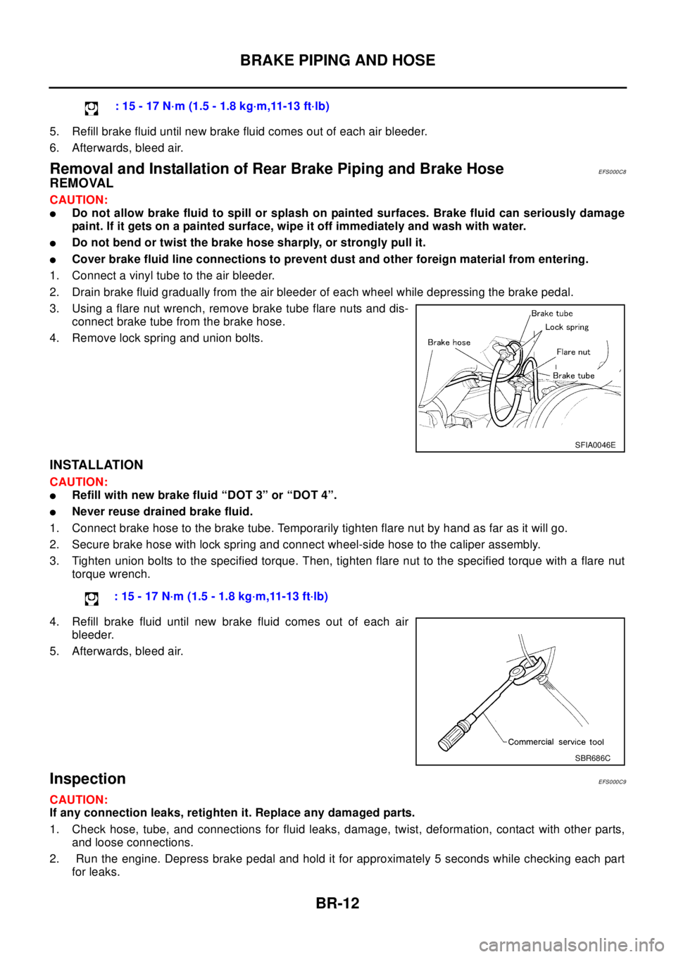
3. Using a flare nut wrench, remove brake tube flare nuts and dis-
connect brake tube from the brake hose.
4. Remove lock spring and union bolts.
INSTALLATION
CAUTION:
lRefill with new brake fluid “DOT 3” or “DOT 4”.
lNever reuse drained brake fluid.
1. Connect brake hose to the brake tube. Temporarily tighten flare nut by hand as far as it will go.
2. Secure brake hose with lock spring and connect wheel-side hose to the caliper assembly.
3. Tighten union bolts to the specified torque. Then, tighten flare nut to the specified torque with a flare nut
torque wrench.
4. Refill brake fluid until new brake fluid comes out of each air
bleeder.
5. Afterwards, bleed air.
InspectionEFS000C9
CAUTION:
If any connection leaks, retighten it. Replace any damaged parts.
1. Check hose, tube, and connections for fluid leaks, damage, twist, deformation, contact with other parts,
and loose connections.
2. Run the engine. Depress brake pedal and hold it for approximately 5 seconds while checking each part
for leaks.:15-17N·m(1.5-1.8kg·m,11-13ft·lb)
SFIA0046E
: 15 - 17 N·m (1.5 - 1.8 kg·m,11-13 ft·lb)
SBR686C
Page 856 of 3066

BR-22
FRONT DISC BRAKE
Pad Replacement
EFS000CI
REMOVAL
CAUTION:
When replacing brake pads, always replace inner shims, outer shims, and shim covers as a set.
1. Remove master cylinder reservoir tank cap.
2. Remove lower sliding pin bolt.
3. Hang cylinder body with a wire, and remove pads, pad retainers,
shims and pad return springs.
INSTALLATION
1. Apply brake grease on back of the pad and both sides of the shim. Install inner shim and inner shim cover
to inner pad, outer shim to outer pad.
2. Apply brake grease on the pad retainer pad contact surface. Install pad retainers, pads and pad return
springs to the torque member.
3. Connect cylinder body to the torque member.
CAUTION:
When replacing pads with new ones, press piston in until the pads can be installed. Carefully mon-
itor brake master cylinder reservoir fluid level. Brake fluid will return, raising master cylinder res-
ervoir tank fluid level.
4. Insert lower sliding pin bolt and tighten to the specified torque.
5. Check brakes for drag.
Caliper Removal and InstallationEFS000CJ
REMOVAL
1. Connect a vinyl tube to the air bleeder.
2. Drain brake fluid gradually from air bleeder while depressing brake pedal.
SBR433D
SBR932C
Page 857 of 3066
FRONT DISC BRAKE
BR-23
C
D
E
G
H
I
J
K
L
MA
B
BR
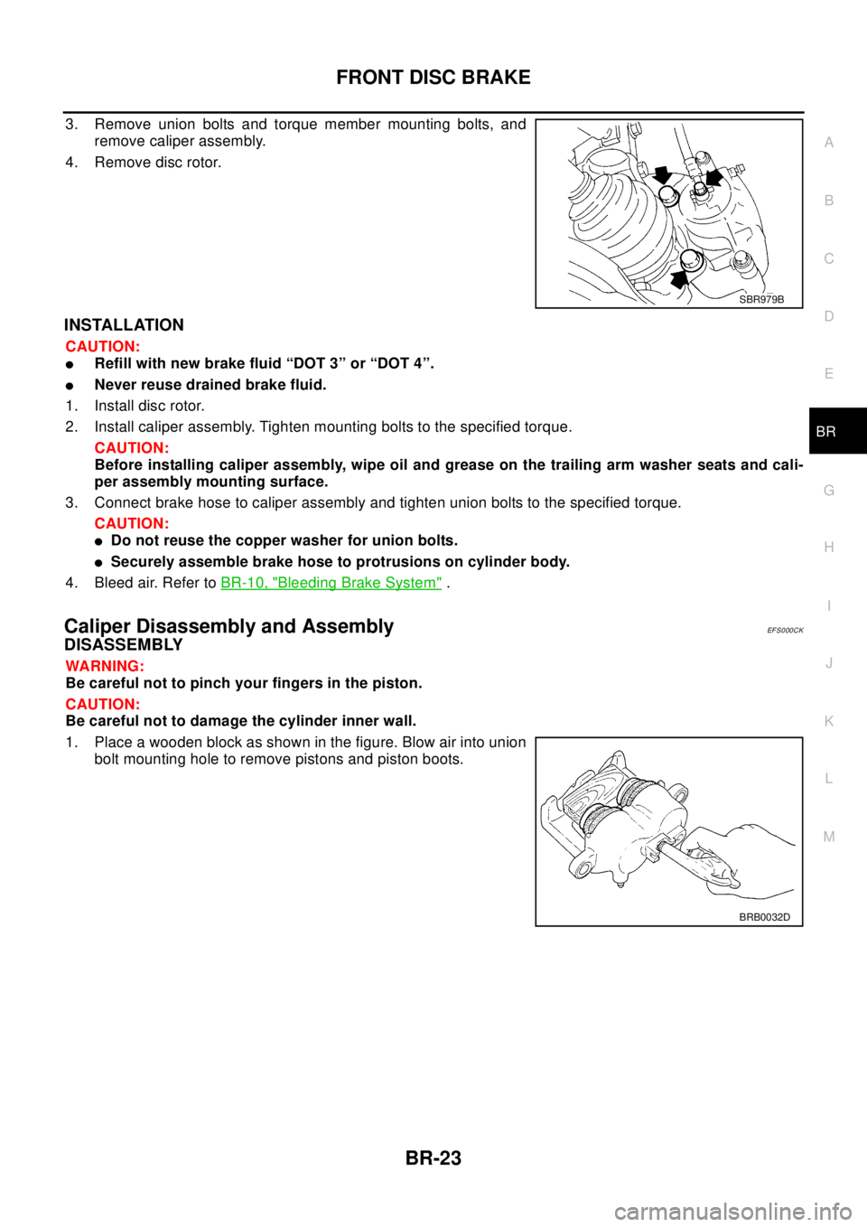
3. Remove union bolts and torque member mounting bolts, and
remove caliper assembly.
4. Remove disc rotor.
INSTALLATION
CAUTION:
lRefill with new brake fluid “DOT 3” or “DOT 4”.
lNever reuse drained brake fluid.
1. Install disc rotor.
2. Install caliper assembly. Tighten mounting bolts to the specified torque.
CAUTION:
Before installing caliper assembly, wipe oil and grease on the trailing arm washer seats and cali-
per assembly mounting surface.
3. Connect brake hose to caliper assembly and tighten union bolts to the specified torque.
CAUTION:
lDo not reuse the copper washer for union bolts.
lSecurely assemble brake hose to protrusions on cylinder body.
4. Bleed air. Refer toBR-10, "
Bleeding Brake System".
Caliper Disassembly and AssemblyEF S0 00 CK
DISASSEMBLY
WA RN ING:
Be careful not to pinch your fingers in the piston.
CAUTION:
Be careful not to damage the cylinder inner wall.
1. Place a wooden block as shown in the figure. Blow air into union
bolt mounting hole to remove pistons and piston boots.
SBR979B
BRB0032D
Page 863 of 3066
REAR DISC BRAKE
BR-29
C
D
E
G
H
I
J
K
L
MA
B
BR
Caliper Removal and InstallationEFS00180
REMOVAL
1. Connect a vinyl tube to the air bleeder.
2. Drain brake fluid gradually from air bleeder while depressing
brake pedal.
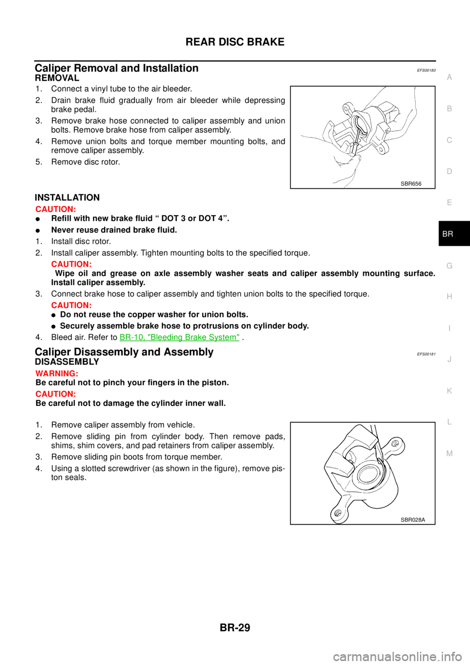
3. Remove brake hose connected to caliper assembly and union
bolts. Remove brake hose from caliper assembly.
4. Remove union bolts and torque member mounting bolts, and
remove caliper assembly.
5. Remove disc rotor.
INSTALLATION
CAUTION:
lRefill with new brake fluid “ DOT 3 or DOT 4”.
lNever reuse drained brake fluid.
1. Install disc rotor.
2. Install caliper assembly. Tighten mounting bolts to the specified torque.
CAUTION:
Wipe oil and grease on axle assembly washer seats and caliper assembly mounting surface.
Install caliper assembly.
3. Connect brake hose to caliper assembly and tighten union bolts to the specified torque.
CAUTION:
lDo not reuse the copper washer for union bolts.
lSecurely assemble brake hose to protrusions on cylinder body.
4. Bleed air. Refer toBR-10, "
Bleeding Brake System".
Caliper Disassembly and AssemblyEFS00181
DISASSEMBLY
WA RN ING:
Be careful not to pinch your fingers in the piston.
CAUTION:
Be careful not to damage the cylinder inner wall.
1. Remove caliper assembly from vehicle.
2. Remove sliding pin from cylinder body. Then remove pads,
shims, shim covers, and pad retainers from caliper assembly.
3. Remove sliding pin boots from torque member.
4. Using a slotted screwdriver (as shown in the figure), remove pis-
ton seals.
SBR656
SBR028A
Page 1003 of 3066
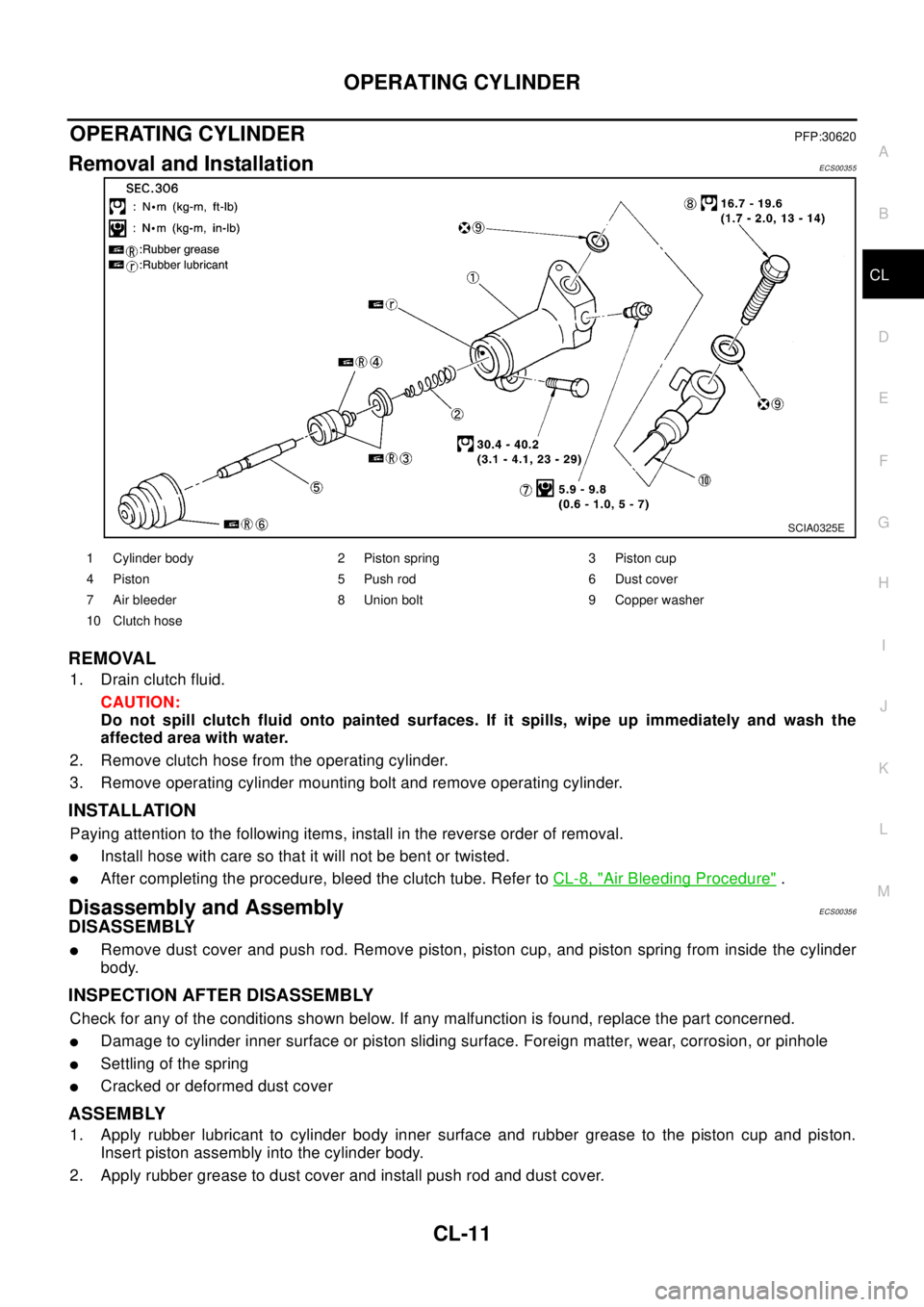
OPERATING CYLINDER
CL-11
D
E
F
G
H
I
J
K
L
MA
B
CL
OPERATING CYLINDERPFP:30620
Removal and InstallationECS00355
REMOVAL
1. Drainclutchfluid.
CAUTION:
Do not spill clutch fluid onto painted surfaces. If it spills, wipe up immediately and wash the
affected area with water.
2. Remove clutch hose from the operating cylinder.
3. Remove operating cylinder mounting bolt and remove operating cylinder.
INSTALLATION
Paying attention to the following items, install in the reverse order of removal.
lInstall hose with care so that it will not be bent or twisted.
lAfter completing the procedure, bleed the clutch tube. Refer toCL-8, "Air Bleeding Procedure".
Disassembly and AssemblyECS00356
DISASSEMBLY
lRemove dust cover and push rod. Remove piston, piston cup, and piston spring from inside the cylinder
body.
INSPECTION AFTER DISASSEMBLY
Check for any of the conditions shown below. If any malfunction is found, replace the part concerned.
lDamage to cylinder inner surface or piston sliding surface. Foreign matter, wear, corrosion, or pinhole
lSettling of the spring
lCracked or deformed dust cover
ASSEMBLY
1. Apply rubber lubricant to cylinder body inner surface and rubber grease to the piston cup and piston.
Insert piston assembly into the cylinder body.
2. Apply rubber grease to dust cover and install push rod and dust cover.
SCIA0325E
1 Cylinder body 2 Piston spring 3 Piston cup
4 Piston 5 Push rod 6 Dust cover
7 Air bleeder 8 Union bolt 9 Copper washer
10 Clutch hose