2003 NISSAN X-TRAIL radiator
[x] Cancel search: radiatorPage 19 of 3066
A/T FLUID
AT-13
D
E
F
G
H
I
J
K
L
MA
B
AT
A/T FLUIDPFP:KLE40
Checking A/T FluidECS004Q7
1. Warm up engine.
2. Check for fluid leakage.
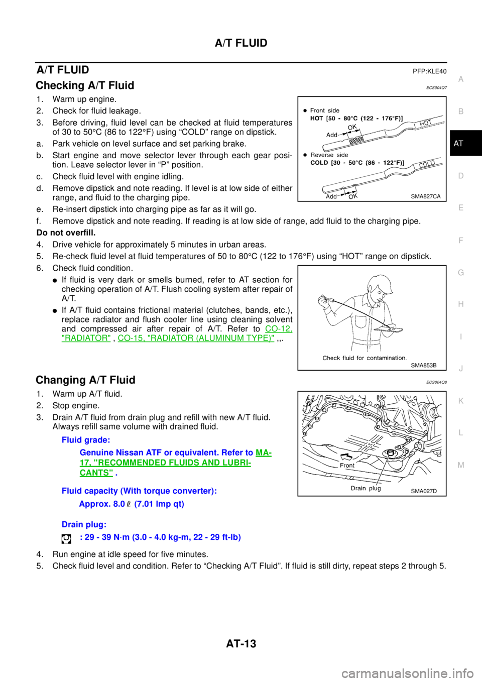
3. Before driving, fluid level can be checked at fluid temperatures
of 30 to 50°C (86 to 122°F) using “COLD” range on dipstick.
a. Park vehicle on level surface and set parking brake.
b. Start engine and move selector lever through each gear posi-
tion. Leave selector lever in “P” position.
c. Check fluid level with engine idling.
d. Remove dipstick and note reading. If level is at low side of either
range, and fluid to the charging pipe.
e. Re-insert dipstick into charging pipe as far as it will go.
f. Remove dipstick and note reading. If reading is at low side of range, add fluid to the charging pipe.
Do not overfill.
4. Drive vehicle for approximately 5 minutes in urban areas.
5. Re-check fluid level at fluid temperatures of 50 to 80°C (122 to 176°F) using “HOT” range on dipstick.
6. Check fluid condition.
lIf fluid is very dark or smells burned, refer to AT section for
checking operation of A/T. Flush cooling system after repair of
A/T.
lIf A/T fluid contains frictional material (clutches, bands, etc.),
replace radiator and flush cooler line using cleaning solvent
and compressed air after repair of A/T. Refer toCO-12,
"RADIATOR",CO-15, "RADIATOR (ALUMINUM TYPE)",,.
Changing A/T FluidECS004Q8
1. Warm up A/T fluid.
2. Stop engine.
3. Drain A/T fluid from drain plug and refill with new A/T fluid.
Always refill same volume with drained fluid.
4. Run engine at idle speed for five minutes.
5. Check fluid level and condition. Refer to “Checking A/T Fluid”. If fluid is still dirty, repeat steps 2 through 5.
SMA827CA
SMA853B
Fluid grade:
Genuine Nissan ATF or equivalent. Refer toMA-
17, "RECOMMENDED FLUIDS AND LUBRI-
CANTS".
Fluid capacity (With torque converter):
Approx. 8.0 (7.01 lmp qt)
Drain plug:
:29-39N·m(3.0-4.0kg-m,22-29ft-lb)
SMA027D
Page 473 of 3066
![NISSAN X-TRAIL 2003 Electronic Repair Manual DISASSEMBLY
AT-467
[ALL]
D
E
F
G
H
I
J
K
L
MA
B
AT
5. Set manual shaft to position P.
6. Remove park/neutral position (PNP) switch.
7. Remove oil pan and oil pan gasket.
lDo not reuse oil pan bolts.
8 NISSAN X-TRAIL 2003 Electronic Repair Manual DISASSEMBLY
AT-467
[ALL]
D
E
F
G
H
I
J
K
L
MA
B
AT
5. Set manual shaft to position P.
6. Remove park/neutral position (PNP) switch.
7. Remove oil pan and oil pan gasket.
lDo not reuse oil pan bolts.
8](/manual-img/5/57402/w960_57402-472.png)
DISASSEMBLY
AT-467
[ALL]
D
E
F
G
H
I
J
K
L
MA
B
AT
5. Set manual shaft to position P.
6. Remove park/neutral position (PNP) switch.
7. Remove oil pan and oil pan gasket.
lDo not reuse oil pan bolts.
8. Check foreign materials in oil pan to help determine causes of
malfunction. If the fluid is very dark, smells burned, or contains
foreign particles, the frictional material (clutches, band) may
need replacement. A tacky film that will not wipe clean indicates
varnish build up. Varnish can cause valves, servo, and clutches
to stick and can inhibit pump pressure.
lIf frictional material is detected, replace radiator after
repair of A/T. Refer toCO-12, "
RADIATOR".
9. Remove control valve assembly according to the following pro-
cedures.
a. Remove control valve assembly mounting boltsI,Xandl.
b. Remove snap ring from terminal body.
SAT023JA
SAT003F
SAT004F
SCIA0800E
Page 668 of 3066
ATC-90
TROUBLE DIAGNOSIS
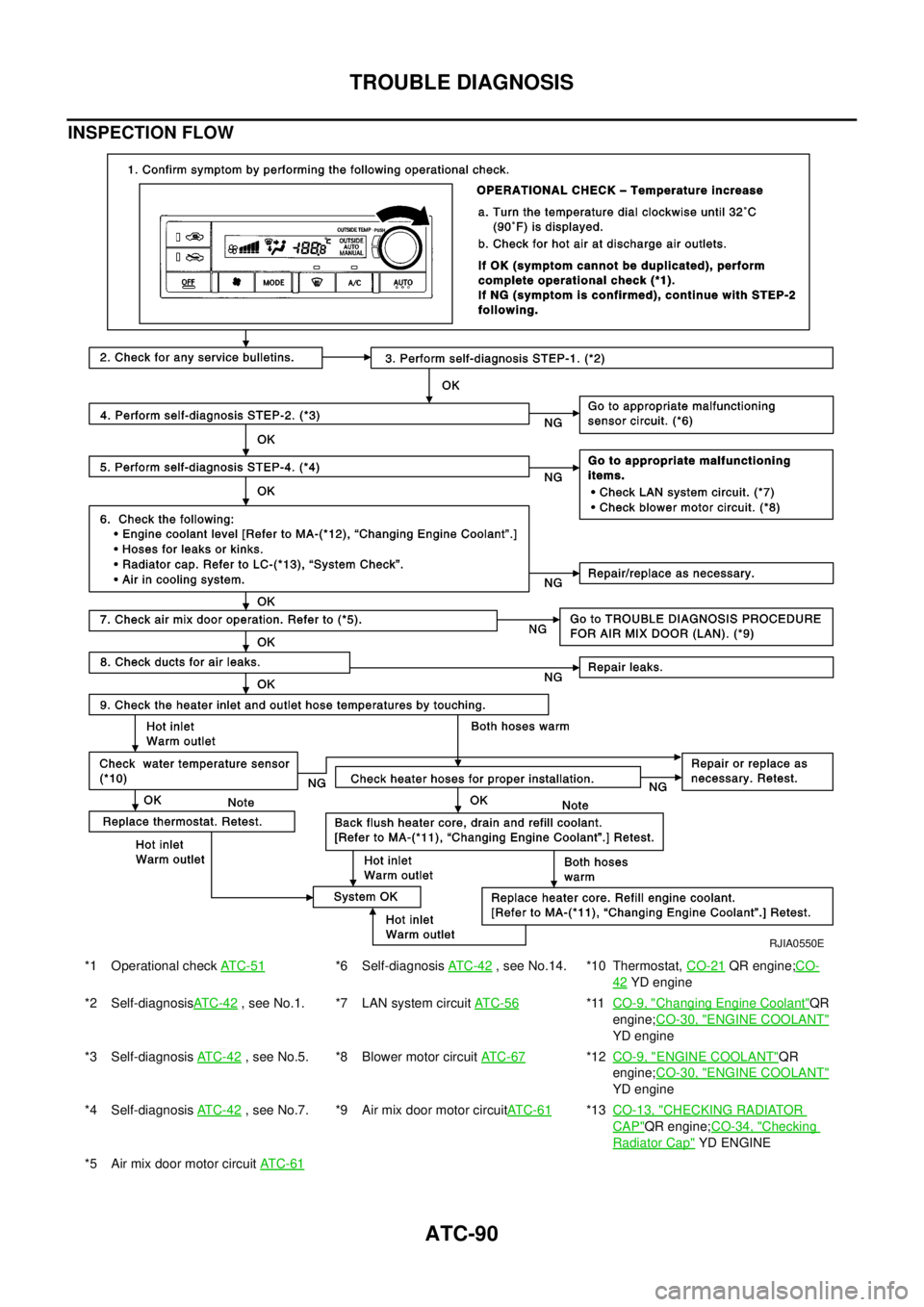
INSPECTION FLOW
*1 Operational checkAT C - 5 1*6 Self-diagnosisAT C -4 2, see No.14. *10 Thermostat,CO-21QR engine;CO-
42YD engine
*2 Self-diagnosisAT C -4 2
, see No.1. *7 LAN system circuitAT C - 5 6*11CO-9, "Changing Engine Coolant"QR
engine;CO-30, "
ENGINE COOLANT"
YD engine
*3 Self-diagnosisAT C - 4 2
, see No.5. *8 Blower motor circuitAT C - 6 7*12CO-9, "ENGINE COOLANT"QR
engine;CO-30, "
ENGINE COOLANT"
YD engine
*4 Self-diagnosisAT C - 4 2
, see No.7. *9 Air mix door motor circuitAT C - 6 1*13CO-13, "CHECKING RADIATOR
CAP"QR engine;CO-34, "Checking
Radiator Cap"YD ENGINE
*5 Air mix door motor circuitAT C - 6 1
RJIA0550E
Page 694 of 3066
ATC-116
HEATER & COOLING UNIT ASSEMBLY
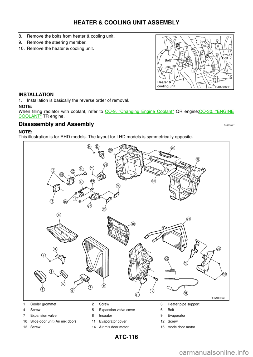
8. Remove the bolts from heater & cooling unit.
9. Remove the steering member.
10. Remove the heater & cooling unit.
INSTALLATION
1. Installation is basically the reverse order of removal.
NOTE:
When filling radiator with coolant, refer toCO-9, "
Changing Engine Coolant"QR engine;CO-30, "ENGINE
COOLANT"TR engine.
Disassembly and AssemblyEJ S00 0UU
NOTE:
This illustration is for RHD models. The layout for LHD models is symmetrically opposite.
RJIA0063E
1 Cooler grommet 2 Screw 3 Heater pipe support
4 Screw 5 Expansion valve cover 6 Bolt
7 Expansion valve 8 Insuator 9 Evaporator
10 Slide door unit (Air mix door) 11 Evaporator cover 12 Screw
13 Screw 14 Air mix door motor 15 mode door motor
RJIA0064J
Page 716 of 3066
ATC-138
REFRIGERANT LINES
Removal and Installation for Dual-pressure Switch
EJS001F6
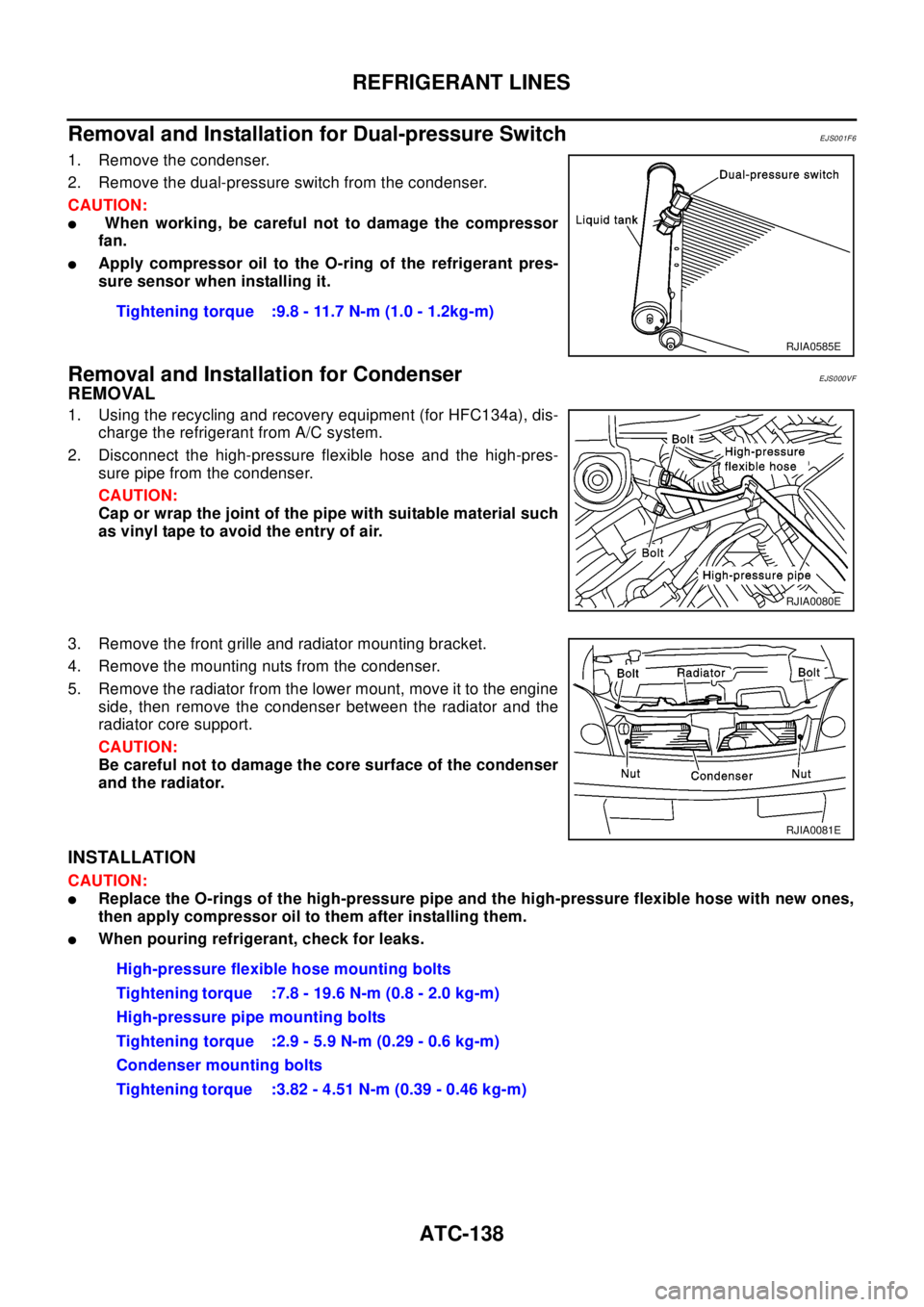
1. Remove the condenser.
2. Remove the dual-pressure switch from the condenser.
CAUTION:
lWhen working, be careful not to damage the compressor
fan.
lApply compressor oil to the O-ring of the refrigerant pres-
sure sensor when installing it.
Removal and Installation for CondenserEJS000VF
REMOVAL
1. Using the recycling and recovery equipment (for HFC134a), dis-
charge the refrigerant from A/C system.
2. Disconnect the high-pressure flexible hose and the high-pres-
sure pipe from the condenser.
CAUTION:
Cap or wrap the joint of the pipe with suitable material such
as vinyl tape to avoid the entry of air.
3. Remove the front grille and radiator mounting bracket.
4. Remove the mounting nuts from the condenser.
5. Remove the radiator from the lower mount, move it to the engine
side, then remove the condenser between the radiator and the
radiator core support.
CAUTION:
Be careful not to damage the core surface of the condenser
and the radiator.
INSTALLATION
CAUTION:
lReplace the O-rings of the high-pressure pipe and the high-pressure flexible hose with new ones,
then apply compressor oil to them after installing them.
lWhen pouring refrigerant, check for leaks.Tightening torque :9.8 - 11.7 N-m (1.0 - 1.2kg-m)
RJIA0585E
RJIA0080E
RJIA0081E
High-pressure flexible hose mounting bolts
Tightening torque :7.8 - 19.6 N-m (0.8 - 2.0 kg-m)
High-pressure pipe mounting bolts
Tightening torque :2.9 - 5.9 N-m (0.29 - 0.6 kg-m)
Condenser mounting bolts
Tightening torque :3.82 - 4.51 N-m (0.39 - 0.46 kg-m)
Page 1011 of 3066
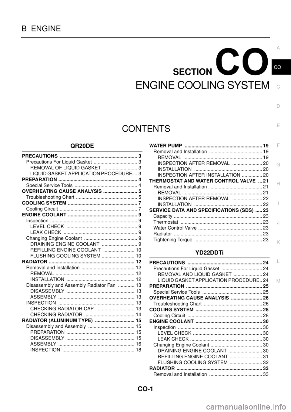
CO-1
ENGINE COOLING SYSTEM
B ENGINE
CONTENTS
C
D
E
F
G
H
I
J
K
L
M
SECTION
A
CO
ENGINE COOLING SYSTEM
QR20DE
PRECAUTIONS .......................................................... 3
Precautions For Liquid Gasket ................................. 3
REMOVAL OF LIQUID GASKET .......................... 3
LIQUID GASKET APPLICATION PROCEDURE..... 3
PREPARATION ........................................................... 4
Special Service Tools ............................................... 4
OVERHEATING CAUSE ANALYSIS .......................... 5
Troubleshooting Chart .............................................. 5
COOLING SYSTEM .................................................... 7
Cooling Circuit .......................................................... 7
ENGINE COOLANT .................................................... 9
Inspection ................................................................. 9
LEVEL CHECK ..................................................... 9
LEAK CHECK ....................................................... 9
Changing Engine Coolant ........................................ 9
DRAINING ENGINE COOLANT ........................... 9
REFILLING ENGINE COOLANT ........................ 10
FLUSHING COOLING SYSTEM ......................... 10
RADIATOR ................................................................ 12
Removal and Installation ........................................ 12
REMOVAL ........................................................... 12
INSTALLATION ................................................... 12
Disassembly and Assembly Radiator Fan ............. 13
DISASSEMBLY ................................................... 13
ASSEMBLY ......................................................... 13
INSPECTION ......................................................... 13
CHECKING RADIATOR CAP .............................. 13
CHECKING RADIATOR ...................................... 14
RADIATOR (ALUMINUM TYPE) .............................. 15
Disassembly and Assembly ................................... 15
PREPARATION ................................................... 15
DISASSEMBLY ................................................... 15
ASSEMBLY ......................................................... 16
INSPECTION ...................................................... 18WATER PUMP .......................................................... 19
Removal and Installation ........................................ 19
REMOVAL ........................................................... 19
INSPECTION AFTER REMOVAL ....................... 20
INSTALLATION ................................................... 20
INSPECTION AFTER INSTALLATION ................ 20
THERMOSTAT AND WATER CONTROL VALVE .... 21
Removal and Installation ........................................ 21
REMOVAL ........................................................... 21
INSPECTION AFTER REMOVAL ....................... 22
INSTALLATION ................................................... 22
SERVICE DATA AND SPECIFICATIONS (SDS) ...... 23
Capacity .................................................................. 23
Thermostat ............................................................. 23
Water Control Valve ................................................ 23
Radiator .................................................................. 23
Tightening Torque ................................................... 23
YD22DDTi
PRECAUTIONS ........................................................ 24
Precautions For Liquid Gasket ............................... 24
REMOVAL AND LIQUID GASKET ...................... 24
LIQUID GASKET APPLICATION PROCEDURE... 24
PREPARATION ......................................................... 25
Special Service Tools ............................................. 25
OVERHEATING CAUSE ANALYSIS ........................ 26
Troubleshooting Chart ............................................ 26
COOLING SYSTEM .................................................. 28
Cooling Circuit ........................................................ 28
ENGINE COOLANT .................................................. 30
Inspection ............................................................... 30
LEVEL CHECK .................................................... 30
LEAK CHECK ...................................................... 30
Changing Engine Coolant ....................................... 30
DRAINING ENGINE COOLANT .......................... 30
REFILLING ENGINE COOLANT ......................... 31
FLUSHING COOLING SYSTEM ......................... 32
RADIATOR ................................................................ 33
Removal and Installation ........................................ 33
Page 1012 of 3066

CO-2
REMOVAL ........................................................... 33
INSTALLATION .................................................... 33
Disassembly and Assembly Radiator Fan .............. 34
DISASSEMBLY ................................................... 34
ASSEMBLY ......................................................... 34
Checking Radiator Cap .......................................... 34
Checking Radiator .................................................. 35
RADIATOR (ALLUMINUM TYPE) ............................. 36
Disassembly and Assembly .................................... 36
PREPARATION ................................................... 36
DISASSEMBLY ................................................... 36
ASSEMBLY ......................................................... 37
INSPECTION ....................................................... 39WATER PUMP ...........................................................40
Removal and Installation .........................................40
REMOVAL ............................................................40
INSPECTION AFTER REMOVAL ........................40
INSTALLATION ....................................................40
INSPECTION AFTER INSTALLATION ................41
THERMOSTAT AND WATER PIPING .......................42
Removal and Installation .........................................42
REMOVAL ............................................................42
INSPECTION AFTER REMOVAL ........................43
INSTALLATION ....................................................43
SERVICE DATA AND SPECIFICATIONS (SDS) ......44
Standard and Limit ..................................................44
CAPACITY ...........................................................44
THERMOSTAT .....................................................44
RADIATOR ...........................................................44
Tightening Torque ...................................................44
Page 1014 of 3066
![NISSAN X-TRAIL 2003 Electronic Repair Manual CO-4
[QR20DE]
PREPARATION
PREPARATION
PFP:00002
Special Service ToolsEBS009SA
Tool number
Tool nameDescription
WS39930000
Tube presserPressing the tube of liquid gasket
EG17650301
Radiator cap tester NISSAN X-TRAIL 2003 Electronic Repair Manual CO-4
[QR20DE]
PREPARATION
PREPARATION
PFP:00002
Special Service ToolsEBS009SA
Tool number
Tool nameDescription
WS39930000
Tube presserPressing the tube of liquid gasket
EG17650301
Radiator cap tester](/manual-img/5/57402/w960_57402-1013.png)
CO-4
[QR20DE]
PREPARATION
PREPARATION
PFP:00002
Special Service ToolsEBS009SA
Tool number
Tool nameDescription
WS39930000
Tube presserPressing the tube of liquid gasket
EG17650301
Radiator cap tester adapterAdapting radiator cap tester to radiator filler
neck
a: 28 (1.10) dia.
b: 31.4 (1.236) dia.
c: 41.3 (1.626) dia.
Unit: mm (in)
KV99103510
Radiator plate pliers AInstalling radiator upper and lower tanks
KV99103520
Radiator plate pliers BRemoving radiator upper and lower tanks
S-NT052
S-NT564
S-NT224
S-NT225