2003 NISSAN X-TRAIL engine coolant
[x] Cancel search: engine coolantPage 14 of 3066
AT-8
PRECAUTIONS
lVehicle has TCC shudder and/or no TCC apply. Replace only after all hydraulic and electrical diagnoses
have been made. (Converter clutch material may be glazed.)
lConverter is contaminated with engine coolant containing antifreeze.
lInternal failure of stator roller clutch.
lHeavy clutch debris due to overheating (blue converter).
lSteel particles or clutch lining material found in fluid filter or on magnet when no internal parts in unit are
worn or damaged — indicates that lining material came from converter.
The torque converter should not be replaced if:
lThe fluid has an odor, is discolored, and there is no evidence of metal or clutch facing particles.
lThe threads in one or more of the converter bolt holes are damaged.
lTransaxle failure did not display evidence of damaged or worn internal parts, steel particles or clutch plate
lining material in unit and inside the fluid filter.
lVehicle has been exposed to high mileage (only). The exception may be where the torque converter
clutch dampener plate lining has seen excess wear by vehicles operated in heavy and/or constant traffic,
such as taxi, delivery or police use.
EURO-OBD SELF-DIAGNOSIS — EURO-OBD —
lA/T self-diagnosis is performed by the TCM in combination with the ECM. The results can be read through
the blinking pattern of the O/D OFF indicator lamp or the malfunction indicator lamp (MIL). Refer to the
table onAT-42, "
SELF-DIAGNOSTIC RESULT TEST MODE"for the indicator used to display each self-
diagnostic result.
lThe self-diagnostic results indicated by the MIL are automatically stored in both the ECM and TCM mem-
ories.
Always perform the procedure “HOW TO ERASE DTC” onAT-39, "
HOW TO ERASE DTC"to com-
plete the repair and avoid unnecessary blinking of the MIL.
lThe following self-diagnostic items can be detected using ECM self-diagnostic results mode* only when
the O/D OFF indicator lamp does not indicate any malfunctions.
–PNP switch
–A/T 1st, 2nd, 3rd, or 4th gear function
*: For details of EURO-OBD, refer toAT - 3 7 , "
ON BOARD DIAGNOSTIC SYSTEM DESCRIPTION".
lCertain systems and components, especially those related to EURO-OBD, may use a new style
slide-locking type harness connector.
For description and how to disconnect, refer toPG-70, "
HARNESS CONNECTOR".
Wiring Diagrams and Trouble DiagnosisECS004Q4
When you read wiring diagrams, refer to the following:
lGI-14, "How to Read Wiring Diagrams".
lPG-2, "POWER SUPPLY ROUTING".
When you perform trouble diagnosis, refer to the following:
lGI-11, "HOW TO FOLLOW TEST GROUPS IN TROUBLE DIAGNOSES".
l"", “HOW TO PERFORM EFFICIENT DIAGNOSIS FOR AN ELECTRICAL INCIDENT”
Page 44 of 3066
![NISSAN X-TRAIL 2003 Electronic Repair Manual AT-38
[EURO-OBD]
ON BOARD DIAGNOSTIC SYSTEM DESCRIPTION
A sample of CONSULT-II display for DTC is shown in the following
page. DTC or 1st trip DTC of a malfunction is displayed in SELF
DIAGNOSIS mode NISSAN X-TRAIL 2003 Electronic Repair Manual AT-38
[EURO-OBD]
ON BOARD DIAGNOSTIC SYSTEM DESCRIPTION
A sample of CONSULT-II display for DTC is shown in the following
page. DTC or 1st trip DTC of a malfunction is displayed in SELF
DIAGNOSIS mode](/manual-img/5/57402/w960_57402-43.png)
AT-38
[EURO-OBD]
ON BOARD DIAGNOSTIC SYSTEM DESCRIPTION
A sample of CONSULT-II display for DTC is shown in the following
page. DTC or 1st trip DTC of a malfunction is displayed in SELF
DIAGNOSIS mode for “ENGINE” with CONSULT-II. Time data indi-
cates how many times the vehicle was driven after the last detection
of a DTC.
If the DTC is being detected currently, the time data will be “0”.
If a 1st trip DTC is stored in the ECM, the time data will be “1t”.
Freeze Frame Data and 1st Trip Freeze Frame Data
The ECM has a memory function, which stores the driving condition such as fuel system status, calculated
load value, engine coolant temperature, short term fuel trim, long term fuel trim, engine speed and vehicle
speed at the moment the ECM detects a malfunction.
Data which are stored in the ECM memory, along with the 1st trip DTC, are called 1st trip freeze frame data,
and the data, stored together with the DTC data, are called freeze frame data and displayed on CONSULT-II
or GST. The 1st trip freeze frame data can only be displayed on the CONSULT-II screen, not on the GST. For
detail, refer to " ", “CONSULT-II”.
Only one set of freeze frame data (either 1st trip freeze frame data of freeze frame data) can be stored in the
ECM. 1st trip freeze frame data is stored in the ECM memory along with the 1st trip DTC. There is no priority
for 1st trip freeze frame data and it is updated each time a different 1st trip DTC is detected. However, once
freeze frame data (2nd trip detection/MIL on) is stored in the ECM memory, 1st trip freeze frame data is no
longer stored. Remember, only one set of freeze frame data can be stored in the ECM.
The ECM has the following priorities to update the data.
Both 1st trip freeze frame data and freeze frame data (along with the DTCs) are cleared when the ECM mem-
oryiserased.
SAT014K
SAT015K
SAT016K
Priority Items
1 Freeze frame data Misfire — DTC: P0300 - P0306
Fuel Injection System Function — DTC: P0171, P0172, P0174, P0175
2 Except the above items (Includes A/T related items)
3 1st trip freeze frame data
Page 135 of 3066
![NISSAN X-TRAIL 2003 Electronic Repair Manual CAN COMMUNICATION
AT-129
[EURO-OBD]
D
E
F
G
H
I
J
K
L
MA
B
AT
CAN COMMUNICATIONPFP:23710
System DescriptionECS004VP
CAN (Controller Area Network) is a serial communication line for real time applicati NISSAN X-TRAIL 2003 Electronic Repair Manual CAN COMMUNICATION
AT-129
[EURO-OBD]
D
E
F
G
H
I
J
K
L
MA
B
AT
CAN COMMUNICATIONPFP:23710
System DescriptionECS004VP
CAN (Controller Area Network) is a serial communication line for real time applicati](/manual-img/5/57402/w960_57402-134.png)
CAN COMMUNICATION
AT-129
[EURO-OBD]
D
E
F
G
H
I
J
K
L
MA
B
AT
CAN COMMUNICATIONPFP:23710
System DescriptionECS004VP
CAN (Controller Area Network) is a serial communication line for real time application. It is an on-vehicle mul-
tiplex communication line with high data communication speed and excellent error detection ability. Many elec-
tronic control units are equipped onto a vehicle, and each control unit shares information and links with other
control units during operation (not independent). In CAN communication, control units are connected with 2
communication lines (CAN H line, CAN L line) allowing a high rate of information transmission with less wiring.
Each control unit transmits/receives data but selectively reads required data only.
FOR A/T MODELS
System diagram
Input/output signal chart
T: Transmit R: Receive
SKIA0884E
Signals ECM TCM
Engine speed signal T R
Engine coolant temperature signal T R
Accelerator pedal position signal T R
A/T self-diagnosis signal R T
Page 357 of 3066
![NISSAN X-TRAIL 2003 Electronic Repair Manual CAN COMMUNICATION
AT-351
[EXC.F/EURO-OBD]
D
E
F
G
H
I
J
K
L
MA
B
AT
CAN COMMUNICATIONPFP:23710
System DescriptionECS004VQ
CAN (Controller Area Network) is a serial communication line for real time app NISSAN X-TRAIL 2003 Electronic Repair Manual CAN COMMUNICATION
AT-351
[EXC.F/EURO-OBD]
D
E
F
G
H
I
J
K
L
MA
B
AT
CAN COMMUNICATIONPFP:23710
System DescriptionECS004VQ
CAN (Controller Area Network) is a serial communication line for real time app](/manual-img/5/57402/w960_57402-356.png)
CAN COMMUNICATION
AT-351
[EXC.F/EURO-OBD]
D
E
F
G
H
I
J
K
L
MA
B
AT
CAN COMMUNICATIONPFP:23710
System DescriptionECS004VQ
CAN (Controller Area Network) is a serial communication line for real time application. It is an on-vehicle mul-
tiplex communication line with high data communication speed and excellent error detection ability. Many elec-
tronic control units are equipped onto a vehicle, and each control unit shares information and links with other
control units during operation (not independent). In CAN communication, control units are connected with 2
communication lines (CAN H line, CAN L line) allowing a high rate of information transmission with less wiring.
Each control unit transmits/receives data but selectively reads required data only.
FOR A/T MODELS
System diagram
Input/output signal chart
T: Transmit R: Receive
SKIA0884E
Signals ECM TCM
Engine speed signal T R
Engine coolant temperature signal T R
Accelerator pedal position signal T R
A/T self-diagnosis signal R T
Page 604 of 3066
ATC-26
AIR CONDITIONER CONTROL
FAN SPEED CONTROL
Blower speed is automatically controlled based on temperature setting, ambient temperature, in-vehicle tem-
perature, intake temperature, amount of sunload and air mix door position.
With FAN switch set to AUTO, the blower motor starts to gradually increase air flow volume.
When engine coolant temperature is low, the blower motor operation is delayed to prevent cool air from flow-
ing.
INTAKE DOOR CONTROL
The intake doors are automatically controlled by: The temperature setting, ambient temperature, in-vehicle
temperature, intake temperature, amount of sunload and ON-OFF operation of the compressor.
OUTLET DOOR CONTROL
The outlet door is automatically controlled by: The temperature setting, ambient temperature, in-vehicle tem-
perature, intake temperature and amount of sunload.
MAGNET CLUTCH CONTROL
The ECM controls compressor operation using input signals from the throttle position sensor and auto ampli-
fier.
SELF-DIAGNOSTIC SYSTEM
The self-diagnostic system is built into the auto amplifier (LCU) to quickly locate the cause of problems.
Overview of Control systemEJS000TK
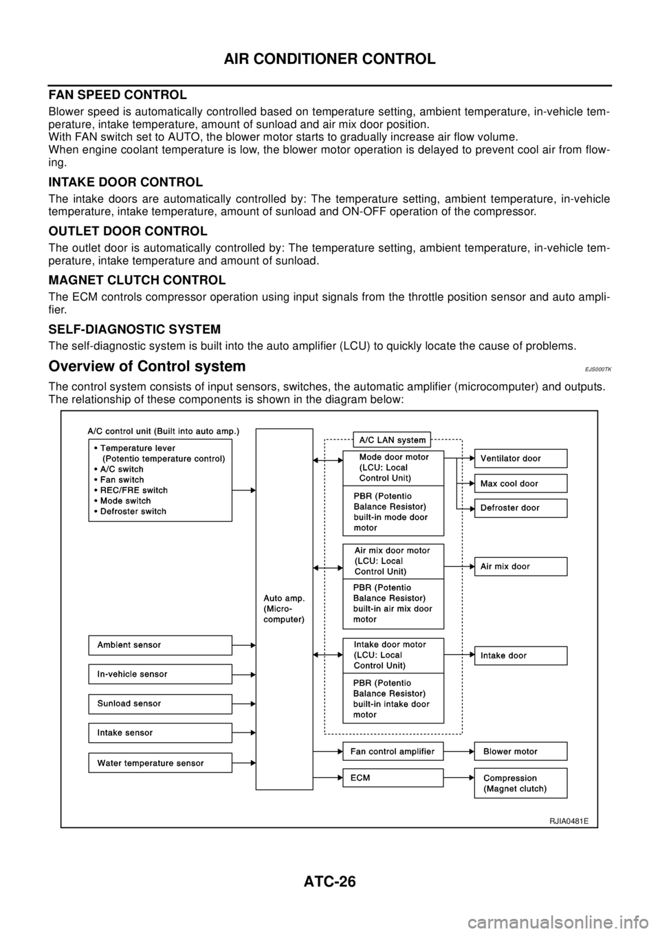
The control system consists of input sensors, switches, the automatic amplifier (microcomputer) and outputs.
The relationship of these components is shown in the diagram below:
RJIA0481E
Page 647 of 3066
TROUBLE DIAGNOSIS
ATC-69
C
D
E
F
G
H
I
K
L
MA
B
AT C
SYSTEM DESCRIPTION
Component Parts
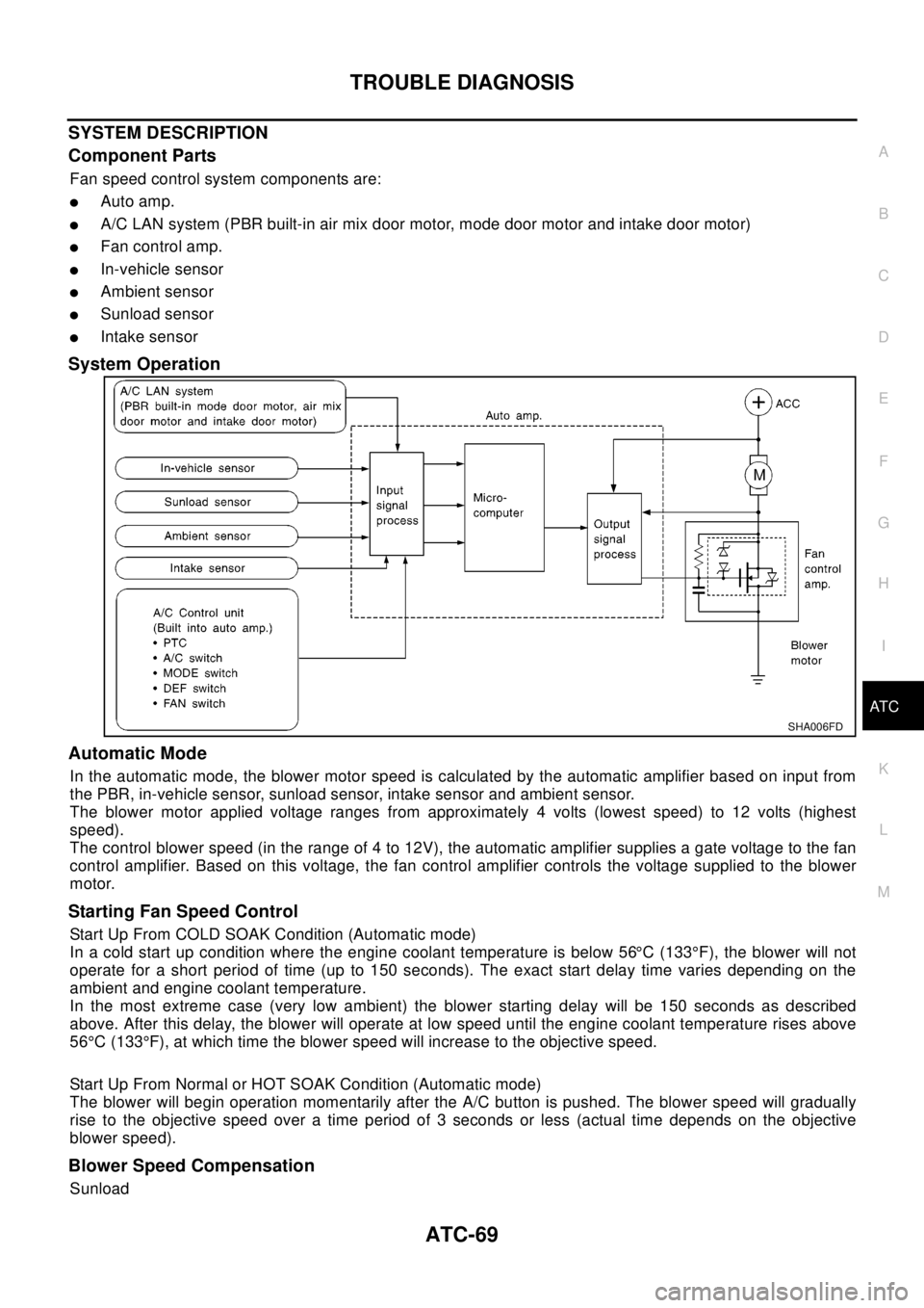
Fan speed control system components are:
lAuto amp.
lA/C LAN system (PBR built-in air mix door motor, mode door motor and intake door motor)
lFan control amp.
lIn-vehicle sensor
lAmbient sensor
lSunload sensor
lIntake sensor
System Operation
Automatic Mode
In the automatic mode, the blower motor speed is calculated by the automatic amplifier based on input from
the PBR, in-vehicle sensor, sunload sensor, intake sensor and ambient sensor.
The blower motor applied voltage ranges from approximately 4 volts (lowest speed) to 12 volts (highest
speed).
The control blower speed (in the range of 4 to 12V), the automatic amplifier supplies a gate voltage to the fan
control amplifier. Based on this voltage, the fan control amplifier controls the voltage supplied to the blower
motor.
Starting Fan Speed Control
Start Up From COLD SOAK Condition (Automatic mode)
In a cold start up condition where the engine coolant temperature is below 56°C (133°F), the blower will not
operate for a short period of time (up to 150 seconds). The exact start delay time varies depending on the
ambient and engine coolant temperature.
In the most extreme case (very low ambient) the blower starting delay will be 150 seconds as described
above. After this delay, the blower will operate at low speed until the engine coolant temperature rises above
56°C (133°F), at which time the blower speed will increase to the objective speed.
Start Up From Normal or HOT SOAK Condition (Automatic mode)
The blower will begin operation momentarily after the A/C button is pushed. The blower speed will gradually
rise to the objective speed over a time period of 3 seconds or less (actual time depends on the objective
blower speed).
Blower Speed Compensation
Sunload
SHA006FD
Page 668 of 3066
ATC-90
TROUBLE DIAGNOSIS
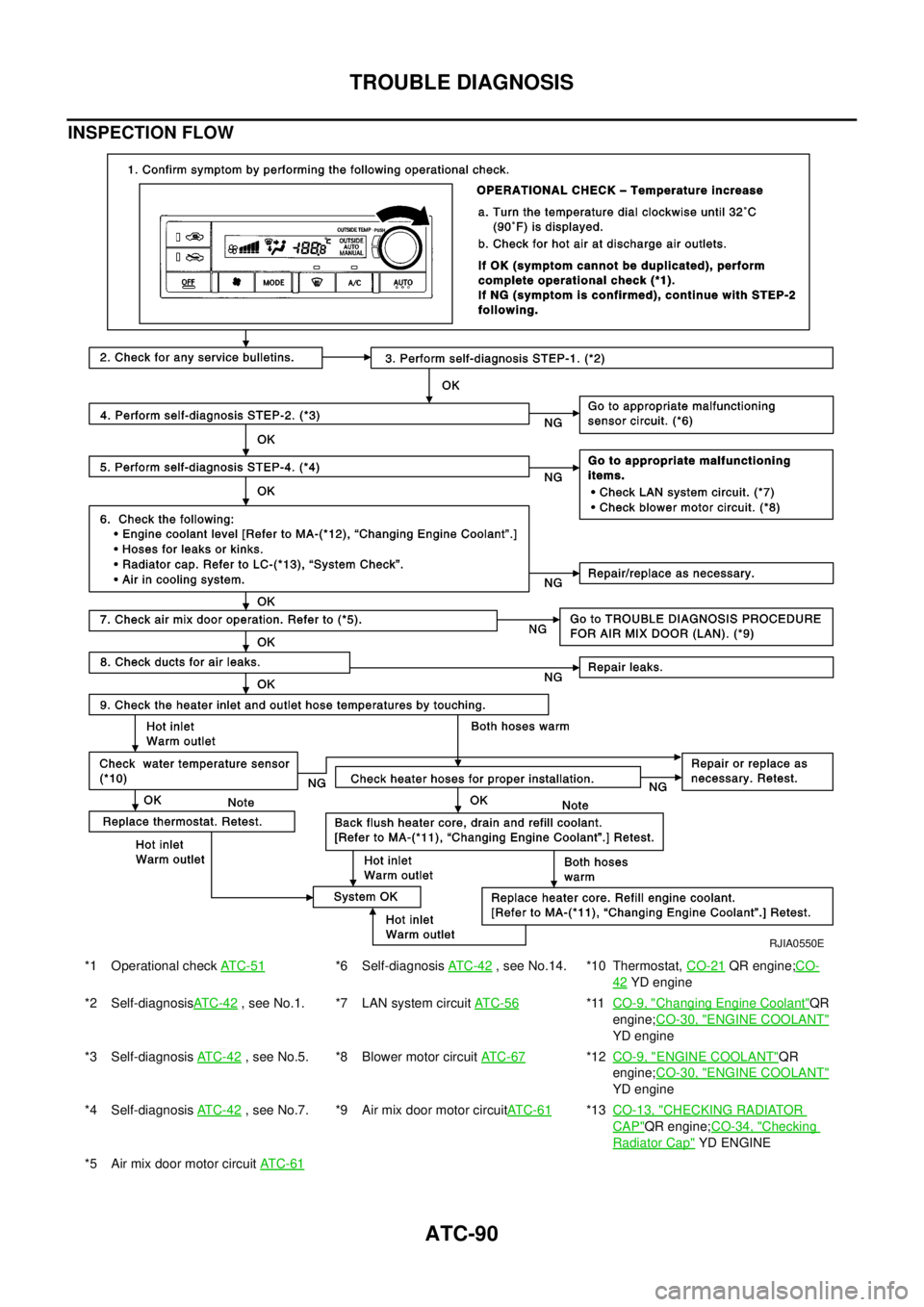
INSPECTION FLOW
*1 Operational checkAT C - 5 1*6 Self-diagnosisAT C -4 2, see No.14. *10 Thermostat,CO-21QR engine;CO-
42YD engine
*2 Self-diagnosisAT C -4 2
, see No.1. *7 LAN system circuitAT C - 5 6*11CO-9, "Changing Engine Coolant"QR
engine;CO-30, "
ENGINE COOLANT"
YD engine
*3 Self-diagnosisAT C - 4 2
, see No.5. *8 Blower motor circuitAT C - 6 7*12CO-9, "ENGINE COOLANT"QR
engine;CO-30, "
ENGINE COOLANT"
YD engine
*4 Self-diagnosisAT C - 4 2
, see No.7. *9 Air mix door motor circuitAT C - 6 1*13CO-13, "CHECKING RADIATOR
CAP"QR engine;CO-34, "Checking
Radiator Cap"YD ENGINE
*5 Air mix door motor circuitAT C - 6 1
RJIA0550E
Page 693 of 3066
HEATER & COOLING UNIT ASSEMBLY
ATC-115
C
D
E
F
G
H
I
K
L
MA
B
AT C
HEATER & COOLING UNIT ASSEMBLYPFP:27110
Removal and InstallationEJS000UT
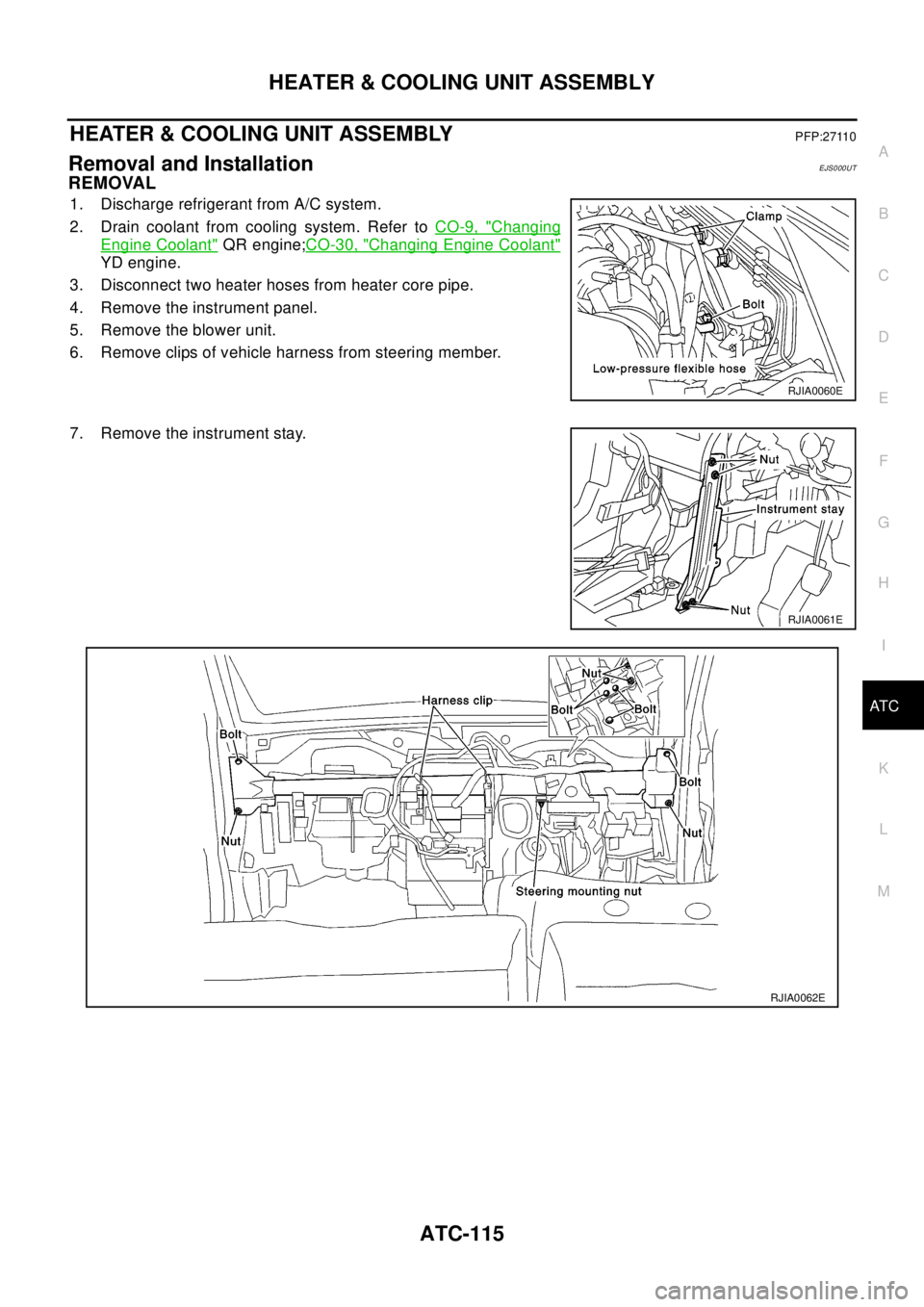
REMOVAL
1. Discharge refrigerant from A/C system.
2. Drain coolant from cooling system. Refer toCO-9, "
Changing
Engine Coolant"QR engine;CO-30, "Changing Engine Coolant"
YD engine.
3. Disconnect two heater hoses from heater core pipe.
4. Remove the instrument panel.
5. Remove the blower unit.
6. Remove clips of vehicle harness from steering member.
7. Remove the instrument stay.
RJIA0060E
RJIA0061E
RJIA0062E