Page 2526 of 3066
MA-34
ENGINE MAINTENANCE (YD22DDTI)
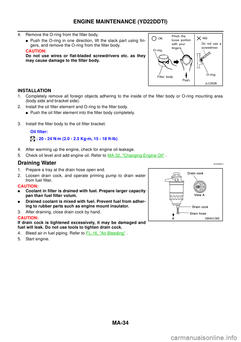
4. Remove the O-ring from the filter body.
lPush the O-ring in one direction, lift the slack part using fin-
gers, and remove the O-ring from the filter body.
CAUTION:
Do not use wires or flat-bladed screwdrivers etc. as they
may cause damage to the filter body.
INSTALLATION
1. Completely remove all foreign objects adhering to the inside of the filter body or O-ring mounting area
(body side and bracket side).
2. Install the oil filter element and O-ring to the filter body.
lPush the oil filter element into the filter body completely.
3. Install the filter body to the oil filter bracket.
4. After warming up the engine, check for engine oil leakage.
5. Check oil level and add engine oil. Refer toMA-32, "
Changing Engine Oil".
Draining WaterELS000CJ
1. Prepare a tray at the drain hose open end.
2. Loosen drain cock, and operate priming pump to drain water
from fuel filter.
CAUTION:
lCoolant in filter is drained with fuel. Prepare larger capacity
pan than fuel filter volum.
lDrained coolant is mixed with fuel. Prevent fuel from adher-
ing to rubber parts such as engine mount insulator.
3. After draining, close drain cock by hand.
CAUTION:
If drain cock is tightened excessively, it may be damaged and
fuel will leak. Do not use tools to tighten drain cock.
4. Bleed air in fuel piping. Refer toFL-16, "
Air Bleeding".
5. Start engine.
JLC292B
Oil filter:
:20-24N·m(2.0-2.5Kg-m,15-18ft-lb)
SBIA0138E
Page 2654 of 3066
MTC-18
TROUBLE DIAGNOSIS
INSPECTION FLOW
*1 QR20DE:CO-9, "Changing Engine
Coolant",YD22DDTi:
CO-30, "
Changing Engine Coolant"
*2 QR20DE:CO-13, "CHECKING RADI-
AT O R C A P", YD22DTi:CO-34,
"Checking Radiator Cap"
*3 :QR20DE:
(Water temperature sensor),
YD22DTi:CO-42, "
Removal and
Installation"
(Thermostat)
*4 QR20DE:CO-9, "
Changing Engine
Coolant",YD22DTi:CO-30, "Chang-
ing Engine Coolant"
*5MTC-7, "Operational Check"*6MTC-3, "SYMPTOM TABLE"
RJIA0612E
Page 2660 of 3066
MTC-24
HEATER UNIT
7. Remove the mounting bolts from heater unit.
8. Remove the steering member.
9. Remove the heater unit.
INSTALLATION
1. Installation is basically the reverse order of removal.
NOTE:
When filling radiator with coolant, refer to QR20DE:CO-9, "
Changing Engine Coolant",YD22DDTi:CO-30,
"Changing Engine Coolant".
Disassembly and AssemblyEJS001FA
NOTE:
This illustration is for RHD models. The layout for LHD models is symmetrically opposite.
RJIA0063E
1 Screw 2 Air mix door link 3 Air mix door gear
4Screw 5Cablebracket 6Screw
7 Foot duct (right) 8 Screw 9 Ventilator door link 2
10 Ventilator door link 2 11 Ventilator door lever 12 Main link
13 Max cool door lever 14 Defroster door lever 15 Heater case (right)
16 Defroster door 17 Ventilator door 18 Max cool door
19 Heater case (left) 20 Screw 21 Heater pipe support
RJIA0613E
Page 2737 of 3066
HARNESS
PG-61
C
D
E
F
G
H
I
J
L
MA
B
PG
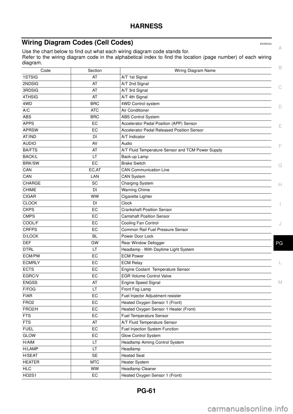
Wiring Diagram Codes (Cell Codes)EKS0032J
Use the chart below to find out what each wiring diagram code stands for.
Refer to the wiring diagram code in the alphabetical index to find the location (page number) of each wiring
diagram.
Code Section Wiring Diagram Name
1STSIG AT A/T 1st Signal
2NDSIG AT A/T 2nd Signal
3RDSIG AT A/T 3rd Signal
4THSIG AT A/T 4th Signal
4WD BRC 4WD Control system
A/C ATC Air Conditioner
ABS BRC ABS Control System
APPS EC Accelerator Pedal Position (APP) Sensor
APRSW EC Accelerator Pedal Released Position Sensor
AT/IND DI A/T Indicator
AUDIO AV Audio
BA/FTS AT A/T Fluid Temperature Sensor and TCM Power Supply
BACK/L LT Back-up Lamp
BRK/SW EC Brake Switch
CAN EC,AT CAN Communication Line
CAN LAN CAN System
CHARGE SC Charging System
CHIME DI Warning Chime
CIGAR WW Cigarette Lighter
CLOCK DI Clock
CKPS EC Crankshaft Position Sensor
CMPS EC Camshaft Position Sensor
COOL/F EC Cooling Fan Control
CRFPS EC Common Rail Fuel Pressure Sensor
D/LOCK BL Power Door Lock
DEF GW Rear Window Defogger
DTRL LT Headlamp - With Daytime Light System
ECM/PW EC ECM Power
ECMRLY EC ECM Relay
ECTS EC Engine Coolant Temperature Sensor
EGRC/V EC EGR Volume Control Valve
ENGSS AT Engine Speed Signal
F/FOG LT Front Fog Lamp
FIAR EC Fuel Injector Adjustment resister
FRO2 EC Heated Oxygen Sensor 1 (Front)
FRO2/H EC Heated Oxygen Sensor 1 Heater (Front)
FTS EC Fuel Temperature Sensor
FTS AT A/T Fluid Temperature Sensor
FUEL EC Fuel Injection System Function
GLOW EC Glow Control System
H/AIM LT Headlamp Aiming Control System
H/LAMP LT Headlamp
H/SEAT SE Heated Seat
HEATER MTC Heater System
HLC WW Headlamp Cleaner
HO2S1 EC Heated Oxygen Sensor 1 (Front)
Page 2798 of 3066
RAX-2
PRECAUTIONS
PRECAUTIONS
PFP:00001
CautionEDS00060
Observe the following precautions when disassembling and servicing drive shaft.
lPerform work in a location which is as dust-free and dirt-free as possible.
lBefore disassembling and servicing, clean the outside of parts.
lThe disassembly and service location must be clean. Care must be taken to prevent parts from becoming
dirty and to prevent the entry of foreign objects.
lDisassembled parts must be carefully reassembled in the correct order. If work is interrupted, a clean
cover must be placed over parts.
lPaper shop cloths must be used. Fabric shop cloths must not be used because of the danger of lint adher-
ing to parts.
lDisassembled parts (except for rubber parts) should be cleaned with kerosene which shall be removed by
blowing with air or wiping with paper shop cloths.
Precautions for Brake SystemEDS0 00 I2
lWhen installing rubber parts, final tightening must be carried out
under unladen condition* with tires on ground.
*: Fuel, radiator coolant and engine oil full. Spare tire, jack,
hand tools and mats in designated positions.
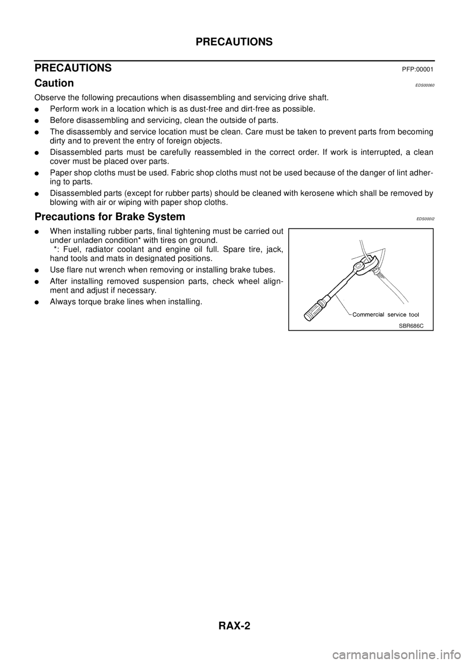
lUse flare nut wrench when removing or installing brake tubes.
lAfter installing removed suspension parts, check wheel align-
ment and adjust if necessary.
lAlways torque brake lines when installing.
SBR686C
Page 2824 of 3066
RFD-2
PRECAUTIONS
PRECAUTIONS
PFP:00001
CautionEDS00056
lBefore starting diagnosis of the vehicle, understand symptoms well. Perform correct and systematic oper-
ations.
lCheck for the correct installation status prior to removal or disassembly. When mating marks are required,
be sure they do not interfere with the function of the parts they are applied to.
lCarry out an overhaul in a clean work place. Using a dust proof room is recommended.
lBefore disassembly, using steam or white gasoline, completely remove sand and mud from the exterior of
the unit, preventing them from entering into the unit during disassembly or assembly.
lCheck appearance of the disassembled parts for damage, deformation, and abnormal wear. If a malfunc-
tion is detected, replace it with a new one.
lNormally replace lock pins, oil seals, and bearings with new ones every time they are removed.
lIn principle, tighten bolts or nuts gradually in several steps working diagonally from inside to outside. If
tightening sequence is specified, observe it.
lClean and flush the parts sufficiently and blow them dry.
lBe careful not to damage the sliding surfaces and mating surfaces.
lWhen applying sealant, remove the old sealant from the mounting surface; then remove any moisture, oil,
and foreign materials from the application and mounting surfaces.
lAlways use shop paper for cleaning the inside of components.
lAvoid using cotton gloves or a shop cloth to prevent entering of lint.
lDuring assembly, observe the specified tightening torque, and apply new differential oil, Vaseline, or Nis-
san MP Special Grease No. 2, as specified for each vehicle, when necessary.
lDo not reuse drained oil. Discard waste oil after oil changes or part treatment in accordance with local
laws and regulations.
Precautions for Brake SystemEDS000HX
lWhen installing rubber parts, final tightening must be carried out
under unladen condition* with tires on ground.
*: Fuel, radiator coolant and engine oil full. Spare tire, jack,
hand tools and mats in designated positions.
lAfter installing removed suspension parts, check wheel align-
ment and adjust if necessary.
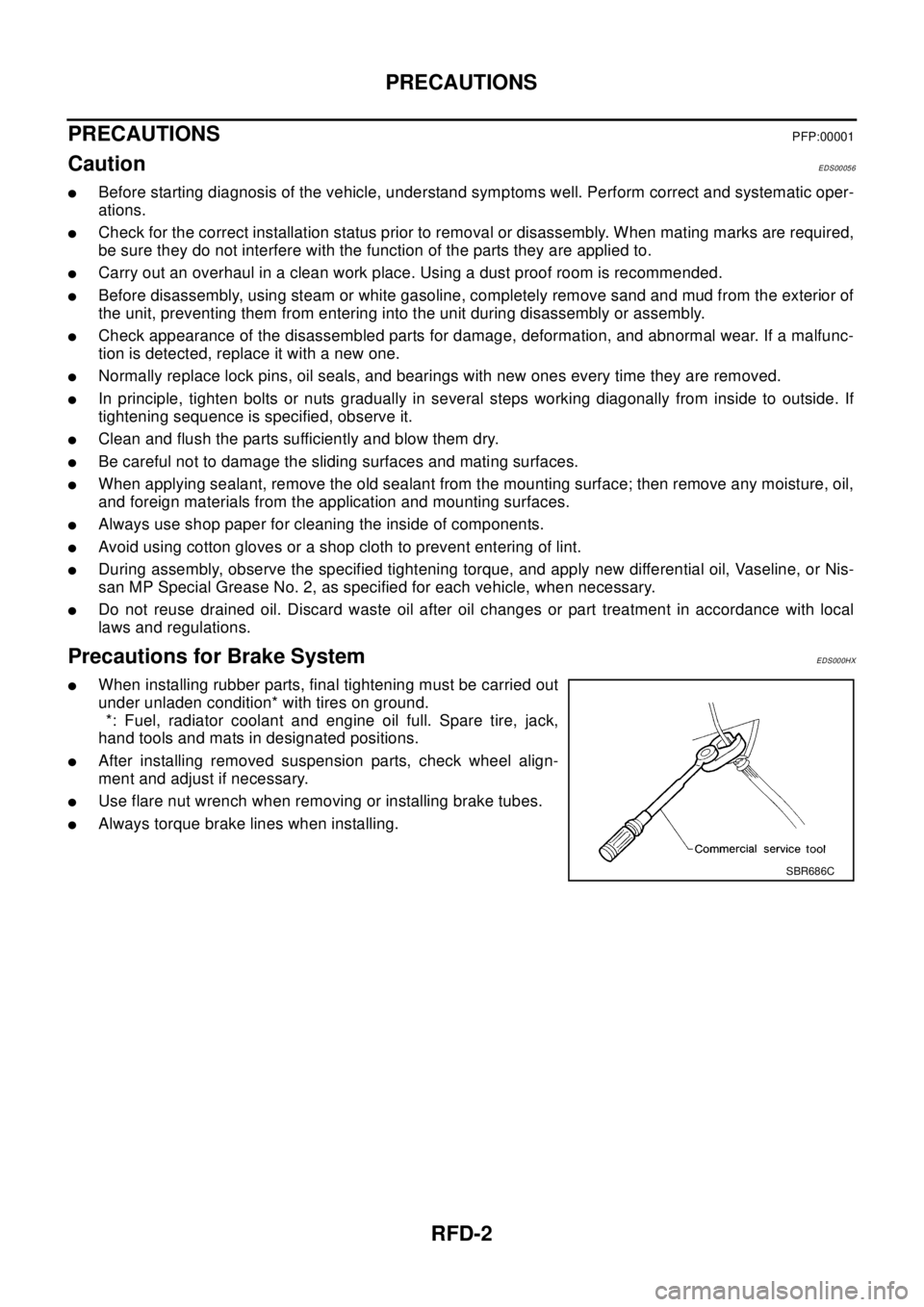
lUse flare nut wrench when removing or installing brake tubes.
lAlways torque brake lines when installing.
SBR686C
Page 2854 of 3066
RSU-2
PRECAUTIONS
PRECAUTIONS
PFP:00001
CautionEES0007C
lFinal tightening of bushings must be carried out under unladen condition with tires on the ground. Oil will
shorten life of bushings. Be sure to wipe off any spilled oil.
l“Unladen condition” means that fuel, coolant and lubricant are full and ready for drive. However, spare tire,
jack, and hand tools should be unloaded.
lAfter installing the removed suspension parts, always check wheel alignment and adjust if necessary.
lReplace the caulking nut with a new one. Install a new nut without wiping the oil off before tightening.
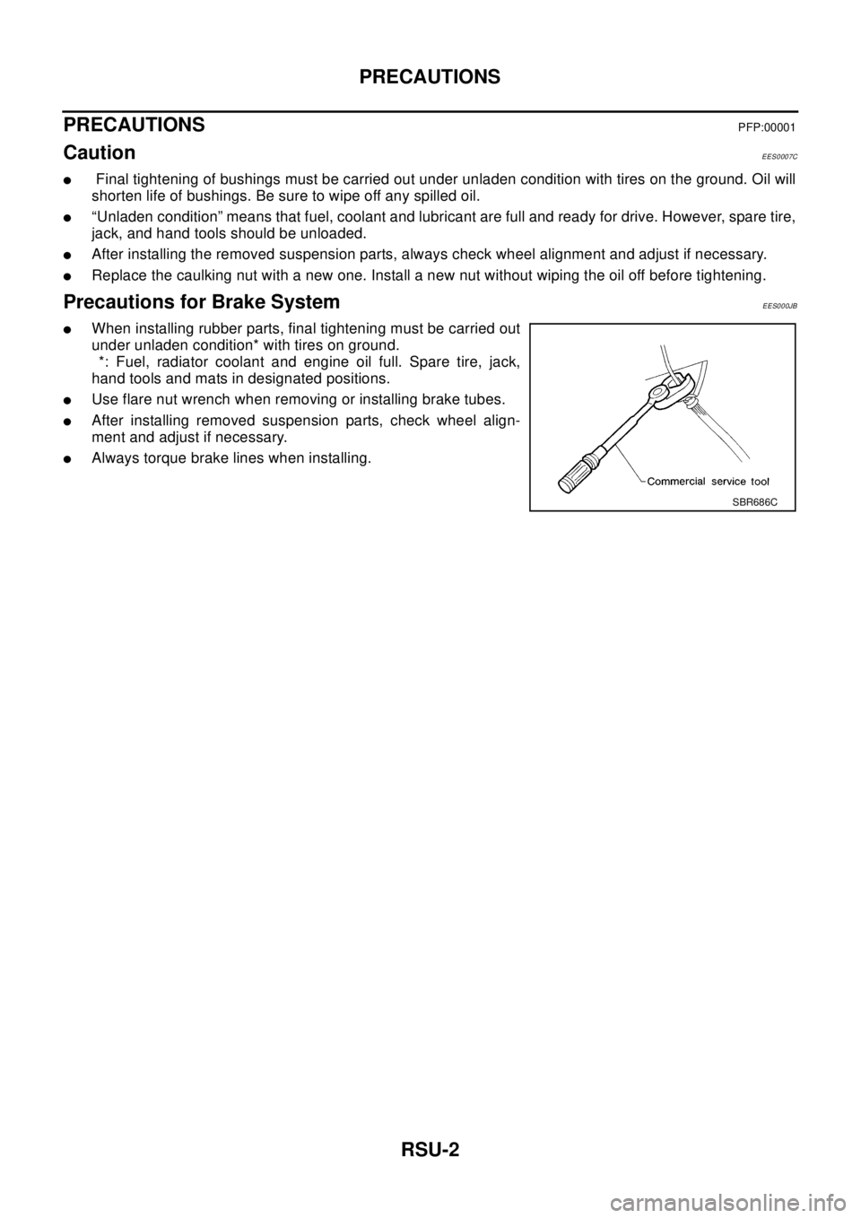
Precautions for Brake SystemEES000JB
lWhen installing rubber parts, final tightening must be carried out
under unladen condition* with tires on ground.
*: Fuel, radiator coolant and engine oil full. Spare tire, jack,
hand tools and mats in designated positions.
lUse flare nut wrench when removing or installing brake tubes.
lAfter installing removed suspension parts, check wheel align-
ment and adjust if necessary.
lAlways torque brake lines when installing.
SBR686C
Page 2866 of 3066
RSU-14
SERVICE DATA AND SPECIFICATIONS (SDS)
SERVICE DATA AND SPECIFICATIONS (SDS)
PFP:00030
General SpecificationEES000J7
Wheel Alignment (Unladen)EES0007N
: Fuel, radiator coolant and engine oil full. Spare tire, jack, hand tools and mats in designated positions.
Wheelarch Height (Unladen)EES000J8
: Fuel, radiator coolant and engine oil full. Spare tire, jack, hand tools and mats in designated positions.Suspension type Parallel link and strut type
Shock absorber type Double-acting hydraulic
Camber
Degree minute (Decimal degree)Minimum-1°25¢(-1.42°)
Nominal-0°40¢(-0.67°)
Maximum 0°05¢(0.08°)
Total Toe-in Distance (A - B) Minimum 0 mm (0 in)
Nominal 1 mm (0.04 in)
Maximum 2 mm (0.08 in)
Applied modelQR20DE engine YD22ET engine
215/65R15
Front (Hf) 773 mm (30.43 in) 771 mm (30.35 in)
Rear (Hr) 786 mm (30.94 in) 785 mm (30.91 in)
SFA818A