2003 NISSAN X-TRAIL fuse box
[x] Cancel search: fuse boxPage 725 of 3066

AUDIO
AV-3
C
D
E
F
G
H
I
J
L
MA
B
AV
AUDIOP F P : 2 8 111
System DescriptionEKS002F2
Refer to Owner's Manual for audio system operating instructions.
Power is supplied at all times
lthrough 15A fuse (No. 32, located in the fusible link and fuse block)
lto audio unit terminal 3
lto CD auto changer terminal 32.
With the ignition switch in the ACC or ON position, power is supplied
lthrough 10A fuse [No. 4, located in the fuse block (J/B)]
lto audio unit terminal 6,
lto CD auto changer terminal 36
Ground is supplied through the case of the audio unit.
Audio signals are supplied
lthrough audio unit terminals 5, 7, 9, 10, 11, 13, 15, 16
lto terminals 1 and 2 of front door speaker LH and RH,
lto terminals 1 and 2 of rear door speaker LH and RH and
lto terminals 1 and 2 of tweeter LH and RH (with 6 speakers)
NATS AUDIO LINK
Description
The link with the NATS IMMU implies that the audio unit can basically only be operated if connected to the
matching NATS IMMU to which the audio unit was initially fitted on the production line.
Since radio operation is impossible after the link with the NATS is disrupted theft of the audio unit is basically
useless since special equipment is required to reset the audio unit.
Initialization process for audio units that are linked to the NATS IMMU
New audio units will be delivered to the factories in the “NEW” state, i.e. ready to be linked with the vehicle's
NATS. When the audio unit in “NEW” state is first switched on at the factory, it will start up communication with
the vehicle's immobilizer control unit (IMMU) and send a code (the “audio unit Code”) to the IMMU. The IMMU
will then store this code, which is unique to each audio unit, in its (permanent) memory.
Upon receipt of the code by the IMMU, the NATS will confirm correct receipt of the audio unit code to the audio
unit. Hereafter, the audio unit will operate as normal.
During the initialization process, “NEW” is displayed on the audio unit display. Normally though, communica-
tion between audio unit and IMMU takes such a short time (300 ms) that the audio unit seems to switch on
directly without showing “NEW” on its display.
Normal operation
Each time the audio unit is switched on afterwards, the audio unit code will be verified between the audio unit
and the NATS before the audio unit becomes operational. During the code verification process, “WAIT” is
shown on the audio unit display. Again, the communication takes such a short time (300 ms) that the audio
unit seems to switch on directly without showing “WAIT” on its display.
When the radio is locked
In case of a audio unit being linked with the vehicle's NATS (immobilizer system), disconnection of the link
between the audio unit and the IMMU will cause the audio unit to switch into the lock (“SECURE”) mode in
which the audio unit is fully inoperative. Hence, repair of the audio unit is basically impossible, unless the
audio unit is reset to the “NEW” state for which special decoding equipment is required.
Clarion has provided their authorized service representatives with so called “decoder boxes” which can bring
the audio unit back to the “NEW” state, enabling the audio unit to be switched on after which repair can be car-
ried out. Subsequently, when the repaired audio unit is delivered to the final user again, it will be in the “NEW”
state to enable re-linking the audio unit to the vehicle's immobilizer system. As a result of the above, repair of
the audio unit can only be done by an authorized Clarion representative (when the owner of the vehicle
requests repair and can show personal identification).
Page 794 of 3066

BL-50
MULTI-REMOTE CONTROL SYSTEM
Power Supply and Ground Circuit Check
EIS001T4
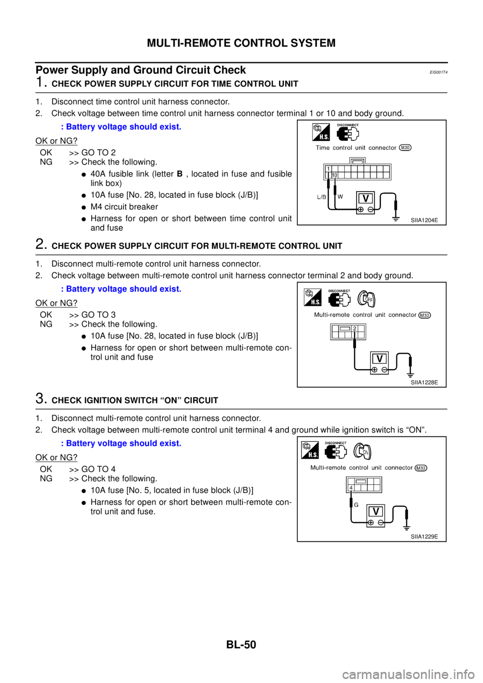
1.CHECK POWER SUPPLY CIRCUIT FOR TIME CONTROL UNIT
1. Disconnect time control unit harness connector.
2. Check voltage between time control unit harness connector terminal 1 or 10 and body ground.
OK or NG?
OK >> GO TO 2
NG >> Check the following.
l40A fusible link (letterB, located in fuse and fusible
link box)
l10A fuse [No. 28, located in fuse block (J/B)]
lM4 circuit breaker
lHarness for open or short between time control unit
and fuse
2.CHECK POWER SUPPLY CIRCUIT FOR MULTI-REMOTE CONTROL UNIT
1. Disconnect multi-remote control unit harness connector.
2. Check voltage between multi-remote control unit harness connector terminal 2 and body ground.
OK or NG?
OK >> GO TO 3
NG >> Check the following.
l10A fuse [No. 28, located in fuse block (J/B)]
lHarness for open or short between multi-remote con-
trol unit and fuse
3.CHECK IGNITION SWITCH “ON” CIRCUIT
1. Disconnect multi-remote control unit harness connector.
2. Check voltage between multi-remote control unit terminal 4 and ground while ignition switch is “ON”.
OK or NG?
OK >> GO TO 4
NG >> Check the following.
l10A fuse [No. 5, located in fuse block (J/B)]
lHarness for open or short between multi-remote con-
trol unit and fuse. : Battery voltage should exist.
SIIA1204E
: Battery voltage should exist.
SIIA1228E
: Battery voltage should exist.
SIIA1229E
Page 824 of 3066

BL-80
NATS (NISSAN ANTI-THEFT SYSTEM)
Diagnostic Procedure 1
EIS001T7
Self-diagnostic results:
“ECM INT CIRC-IMMU” displayed on CONSULT-II screen
1. Confirm SELF-DIAGNOSTIC RESULTS “ECM INT CIRC-IMMU”
displayed on CONSULT-II screen. Ref. part No. B.
2. Replace ECM.
3. Perform initialization with CONSULT-II.
For initialization, refer to “CONSULT-II operation manual NATS”.
Diagnostic Procedure 2EIS001T8
Self-diagnostic results:
“CHAIN OF ECM-IMMU” displayed on CONSULT-II screen
1.CONFIRM SELF-DIAGNOSTIC RESULTS
Confirm SELF-DIAGNOSTIC RESULTS “CHAIN OF ECM-IMMU”
displayed on CONSULT-II screen.
NOTE:
In rare case, “CHAIN OF ECM-IMMU” might be stored during key
registration procedure, even if the system is not malfunctioning.
Is CONSULT-II screen displayed as above?
Yes >>GOTO2
No >> GO TOBL-78, "
SYMPTOM MATRIX CHART 1".
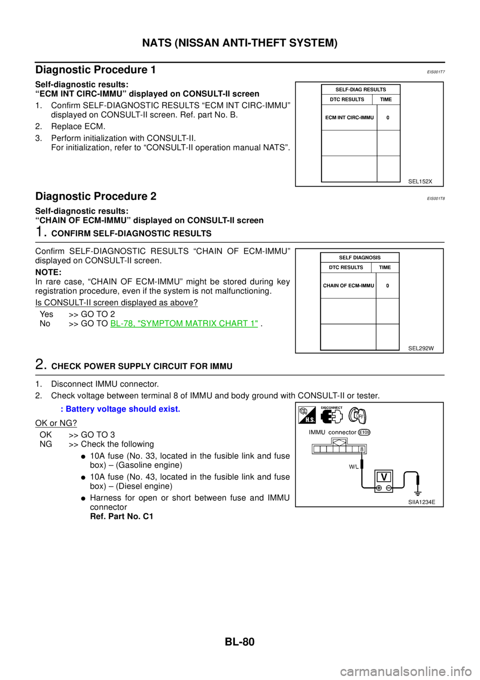
2.CHECK POWER SUPPLY CIRCUIT FOR IMMU
1. Disconnect IMMU connector.
2. Check voltage between terminal 8 of IMMU and body ground with CONSULT-II or tester.
OK or NG?
OK >> GO TO 3
NG >> Check the following
l10A fuse (No. 33, located in the fusible link and fuse
box) – (Gasoline engine)
l10A fuse (No. 43, located in the fusible link and fuse
box) – (Diesel engine)
lHarness for open or short between fuse and IMMU
connector
Ref. Part No. C1
SEL152X
SEL292W
: Battery voltage should exist.
SIIA1234E
Page 911 of 3066
![NISSAN X-TRAIL 2003 Electronic Repair Manual TROUBLE DIAGNOSIS
BRC-43
[4WD/ABS]
C
D
E
G
H
I
J
K
L
MA
B
BRC
3.CHECK CONTINUITY BETWEEN IGNITION SWITCH AND ABS WARNING LAMP.
lDisconnect 4WD/ABS control unit connector.
lCheck continuity between ign NISSAN X-TRAIL 2003 Electronic Repair Manual TROUBLE DIAGNOSIS
BRC-43
[4WD/ABS]
C
D
E
G
H
I
J
K
L
MA
B
BRC
3.CHECK CONTINUITY BETWEEN IGNITION SWITCH AND ABS WARNING LAMP.
lDisconnect 4WD/ABS control unit connector.
lCheck continuity between ign](/manual-img/5/57402/w960_57402-910.png)
TROUBLE DIAGNOSIS
BRC-43
[4WD/ABS]
C
D
E
G
H
I
J
K
L
MA
B
BRC
3.CHECK CONTINUITY BETWEEN IGNITION SWITCH AND ABS WARNING LAMP.
lDisconnect 4WD/ABS control unit connector.
lCheck continuity between ignition switch and 4WD/ABS control module terminal No. 4. (Open circuit
check)
Is inspection result OK?
YES >> Continuity exists. Connect 4WD/ABS control module connector, check again.
NO >> Continuity does not exist. Check ABS warning lamp path.
4.CHECK FUSE.
lCheck if Fuse No.8 is working normally.
Is the check result OK?
YES >> Repair or replace the harness in between 4WD/ABS control unit and IGN.
NO >> Replace the fuse and replace again.
lIf the figure of the monitor is with in±10% of the set value of E-TS solenoid electric current, 4WD/ABS C/
U is operating normally.Check for electric control coupling ASSY is required.
4WD warning lamp does not illuminate with ignition ON.EFS001BR
1.INSPECTION OF BLOWN 4WD WARNING LAMP BULB
lRemove glove box on the passenger side and disconnect the 4WD/ABS control unit connector.
lConfirm continuity between 4WD/ABS control unit connector terminals No. 3 (IGN) and No. 4 (ABS warn-
ing lamp).
Is inspection result OK?
YES >> GO TO 3. (Continuity exists.)
NO >>
lCheck 4WD warning lamp harness.
lRemove meter control module assembly and check for blown 4WD warning lamp bulb.
2.4WD ACTUATOR RELAY HARNESS INSPECTION
lOpen the hood and check that the 4WD relay is properly installed in the relay box.
lConfirm continuity between 4WD/ABS control unit connector terminals No. 7 (4WD warning lamp) and No.
104 (ground).
lConfirm continuity between 4WD/ABS control unit connector terminals No. 3 (IGN) and No. 18 (4WD
actuator relay).
Is inspection result OK?
YES >> Continuity exists. Connect 4WD/ABS control unit connector, check again.
NO >> Check ABS warning lamp harness.
4WD warning lamp does not go out several seconds after engine is started.
(Drive mode indicator lamp goes out.)
EFS001BS
1.USING CONSULT, PERFORM SELF-DIAGNOSIS.
4WD warning lamp does not go out several seconds after the engine is started. (Drive mode indicator lamp
goes out.)
Is inspection result OK?
YES >> No malfunction detected. Perform inspection again.
NO >>
lDetermine the location of the malfunction according to the result of self-diagnosis using CON-
SULT. (Malfunction is present in the 4WD system.)
lCONSULT-II does not display ABS -related trouble codes. Proceed to 2.
Page 969 of 3066
![NISSAN X-TRAIL 2003 Electronic Repair Manual TROUBLE DIAGNOSIS
BRC-101
[ESP/TCS/ABS]
C
D
E
G
H
I
J
K
L
MA
B
BRC
2.SELF-DIAGNOSIS RESULT CHECK 2
1. Disconnect connectors for the ESP/TCS/ABS control unit and the actuator. Securely connect them aga NISSAN X-TRAIL 2003 Electronic Repair Manual TROUBLE DIAGNOSIS
BRC-101
[ESP/TCS/ABS]
C
D
E
G
H
I
J
K
L
MA
B
BRC
2.SELF-DIAGNOSIS RESULT CHECK 2
1. Disconnect connectors for the ESP/TCS/ABS control unit and the actuator. Securely connect them aga](/manual-img/5/57402/w960_57402-968.png)
TROUBLE DIAGNOSIS
BRC-101
[ESP/TCS/ABS]
C
D
E
G
H
I
J
K
L
MA
B
BRC
2.SELF-DIAGNOSIS RESULT CHECK 2
1. Disconnect connectors for the ESP/TCS/ABS control unit and the actuator. Securely connect them again.
2. Perform the self-diagnosis again.
Are any self-diagnosis items indicated again?
YES >> GO TO 3.
NO >> Repair or replace the poorly connected connector.
3.ACTUATOR MOTOR, MOTOR RELAY POWER SUPPLY CIRCUIT INSPECTION
1. Disconnect relay box connectors.
2. Check the voltage between the vehicle-side connector and body ground.
Is inspection result OK?
OK >> GO TO 4.
NG >>
lCheck the fuse 50A.
lCheck for continuity between the battery and the relay box terminal No. 10.
4.ACTUATOR MOTOR AND MOTOR RELAY CIRCUIT CHECK
1. Disconnect connectors for the ESP/TCS/ABS control unit and
the relay box.
2. Check for continuity between the ESP/TCS/ABS control unit,
the relay, and the actuator (vehicle-side connector).
Is inspection result OK?
YES >> GO TO 5.
NO >> Harness malfunction between the ESP/TCS/
ABS control unit, the relay box and the actuator.
SFIA0379E
Relay box
(Vehicle-side connector)Body ground Voltage value
10 – Battery voltage (approx. 12V)
ESP/TCS/ABS
control unit
(Vehicle-side
connector)Relay box
(Vehicle-side
connector)Actuator
(Vehicle-side
connector)Continuity
20 4 — Yes
78—Yes
— 41 [RHD] 21 [RHD] Yes
SFIA0380E
Page 971 of 3066
![NISSAN X-TRAIL 2003 Electronic Repair Manual TROUBLE DIAGNOSIS
BRC-103
[ESP/TCS/ABS]
C
D
E
G
H
I
J
K
L
MA
B
BRC
4.ACTUATOR RELAY POWER SUPPLY CIRCUIT INSPECTION
1. Disconnect relay box connectors.
2. Check the voltage between the vehicle-side co NISSAN X-TRAIL 2003 Electronic Repair Manual TROUBLE DIAGNOSIS
BRC-103
[ESP/TCS/ABS]
C
D
E
G
H
I
J
K
L
MA
B
BRC
4.ACTUATOR RELAY POWER SUPPLY CIRCUIT INSPECTION
1. Disconnect relay box connectors.
2. Check the voltage between the vehicle-side co](/manual-img/5/57402/w960_57402-970.png)
TROUBLE DIAGNOSIS
BRC-103
[ESP/TCS/ABS]
C
D
E
G
H
I
J
K
L
MA
B
BRC
4.ACTUATOR RELAY POWER SUPPLY CIRCUIT INSPECTION
1. Disconnect relay box connectors.
2. Check the voltage between the vehicle-side connector and body
ground.
Is inspection result OK?
YES >> GO TO 5.
NO >>
lCheck the fuse 30A.
lCheck for continuity between the battery and the relay box terminal No. 9. If it is not OK,
replace the fuse or harness.
5.ACTUATOR RELAY POWER CIRCUIT CHECK
1. Disconnect connectors for the ESP/TCS/ABS control unit and
the relay box.
2. Check for continuity between the ESP/TCS/ABS control unit
and the relay box (vehicle-side connector).
Is inspection result OK?
OK >> GO TO 6.
NG >> Harness disconnection between the ESP/TCS/ABS control unit and the relay box.
6.ACTUATOR RELAY UNIT INSPECTION
Check the actuator relay as a unit.
Is inspection result OK?
OK >> Check the ESP/TCS/ABS control unit power supply circuit.
NG >> Replace the actuator relay.
SFIA0382E
RELAY BOX
(Vehicle-side connector)Body ground Voltage value
9 – Battery voltage (approx. 12V)
SFIA0383E
ESP/TCS/ABS control unit
(Vehicle-side connector)Relay box
(Vehicle-side connector)Continuity
25Yes
36 7 Yes
Page 1106 of 3066

DI-52
WARNING CHIME
WARNING CHIME
PFP:24814
System DescriptionEKS002XF
POWER SUPPLY AND GROUND CIRCUIT
Power is supplied at all times
lthrough 10A fuse (No.31, located in fuse and fusible link box)
lto combination switch terminal 11,and
lto daytime light control unit terminal 1(with daytime light control unit).
lthrough 10A fuse [No.28, located in the fuse block (J/B)]
lto key switch terminal 1 and
lto time control unit terminal 1.
With ignition switch in ON or START position, power is supplied
lthrough 10A fuse [No.5, located in the fuse block (J/B)]
lto time control unit terminal 17.
Ground is supplied
lto time control unit terminal 16
lthrough body grounds M27 and M70.
When a signal, or combination of signals, is received by the time control unit, the warning chime will sound.
IGNITION KEY WARNING CHIME
With ignition switch in OFF or ACC position, and the driver's door open and driver’s door locked, the warning
chime will sound. Power is supplied
lthrough key switch terminal 2
lto time control unit terminal 18 and
Ground is supplied
lto time control unit terminal 28
lthrough unlock sensor terminal 5
Unlock sensor terminal 2 is grounded through body grounds M27 and M70, and
Ground is supplied
lto time control unit terminal 30
lthrough front door (driver side) switch terminal 2.
Front door switch (driver side) terminal 3 is grounded through body grounds B8 and B18.
LIGHT WARNING CHIME
With ignition switch OFF position, driver's door open, and lighting switch in 1ST or 2ND position, warning
chime will sound. Power is supplied
lfrom the lighting switch terminal 12 or daytime light control unit terminal 10 (with daytime light system)
lto time control unit terminal 19.
Ground is supplied
lfrom Front door switch (driver side) terminal 2
lto time control unit terminal 30.
Front door switch (driver side) terminal 3 is grounded through body grounds B8 and B18.
Page 1111 of 3066

WARNING CHIME
DI-57
C
D
E
F
G
H
I
J
L
MA
B
DI
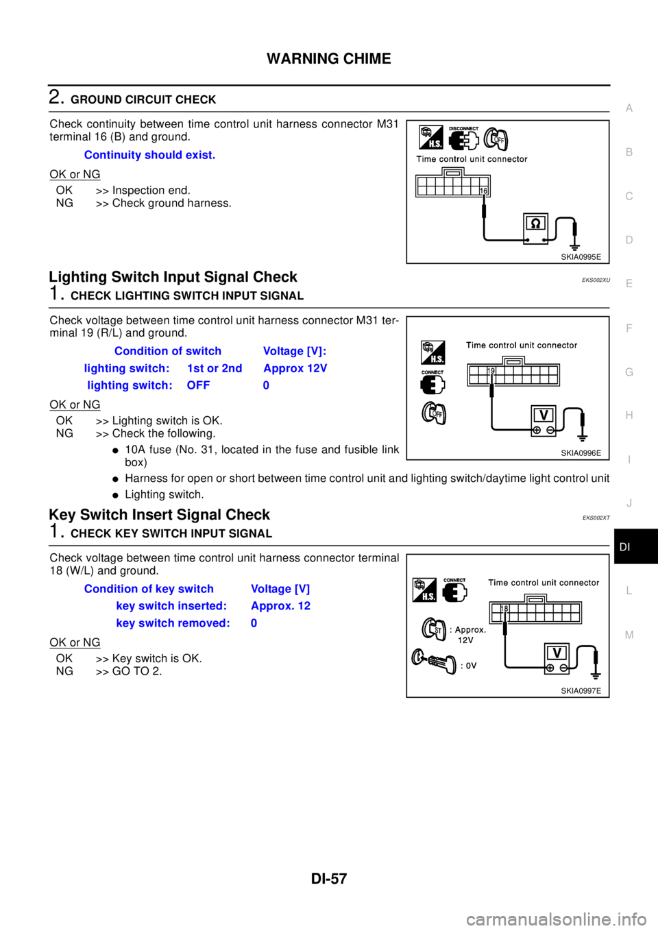
2.GROUND CIRCUIT CHECK
Check continuity between time control unit harness connector M31
terminal 16 (B) and ground.
OK or NG
OK >> Inspection end.
NG >> Check ground harness.
Lighting Switch Input Signal CheckEKS002XU
1.CHECK LIGHTING SWITCH INPUT SIGNAL
Check voltage between time control unit harness connector M31 ter-
minal 19 (R/L) and ground.
OK or NG
OK >> Lighting switch is OK.
NG >> Check the following.
l10A fuse (No. 31, located in the fuse and fusible link
box)
lHarness for open or short between time control unit and lighting switch/daytime light control unit
lLighting switch.
Key Switch Insert Signal CheckEKS002XT
1.CHECK KEY SWITCH INPUT SIGNAL
Check voltage between time control unit harness connector terminal
18 (W/L) and ground.
OK or NG
OK >>KeyswitchisOK.
NG >> GO TO 2.Continuity should exist.
SKIA0995E
Condition of switch Voltage [V]:
lighting switch: 1st or 2nd Approx 12V
lighting switch: OFF 0
SKIA0996E
Condition of key switch Voltage [V]
key switch inserted: Approx. 12
key switch removed: 0
SKIA0997E