2003 NISSAN X-TRAIL fuse box
[x] Cancel search: fuse boxPage 2312 of 3066

REAR WINDOW DEFOGGER
GW-9
C
D
E
F
G
H
J
K
L
MA
B
GW
REAR WINDOW DEFOGGERPFP:25350
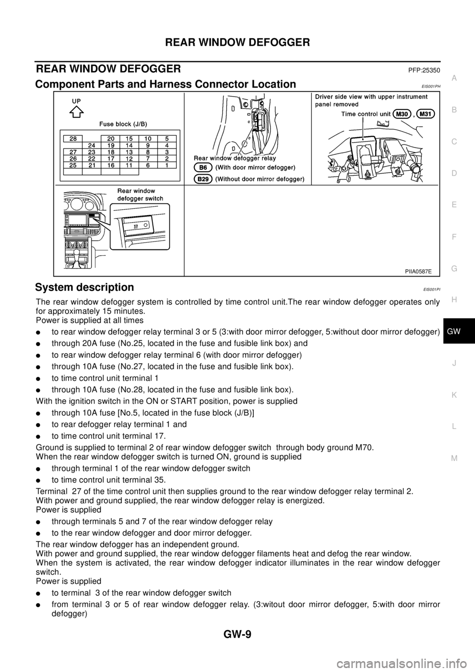
Component Parts and Harness Connector LocationEIS001PH
System descriptionEIS001PI
The rear window defogger system is controlled by time control unit.The rear window defogger operates only
for approximately 15 minutes.
Power is supplied at all times
lto rear window defogger relay terminal 3 or 5 (3:with door mirror defogger, 5:without door mirror defogger)
lthrough 20A fuse (No.25, located in the fuse and fusible link box) and
lto rear window defogger relay terminal 6 (with door mirror defogger)
lthrough 10A fuse (No.27, located in the fuse and fusible link box).
lto time control unit terminal 1
lthrough 10A fuse (No.28, located in the fuse and fusible link box).
With the ignition switch in the ON or START position, power is supplied
lthrough 10A fuse [No.5, located in the fuse block (J/B)]
lto rear defogger relay terminal 1 and
lto time control unit terminal 17.
Ground is supplied to terminal 2 of rear window defogger switch through body ground M70.
When the rear window defogger switch is turned ON, ground is supplied
lthrough terminal 1 of the rear window defogger switch
lto time control unit terminal 35.
Terminal 27 of the time control unit then supplies ground to the rear window defogger relay terminal 2.
With power and ground supplied, the rear window defogger relay is energized.
Power is supplied
lthrough terminals 5 and 7 of the rear window defogger relay
lto the rear window defogger and door mirror defogger.
The rear window defogger has an independent ground.
With power and ground supplied, the rear window defogger filaments heat and defog the rear window.
When the system is activated, the rear window defogger indicator illuminates in the rear window defogger
switch.
Power is supplied
lto terminal 3 of the rear window defogger switch
lfrom terminal 3 or 5 of rear window defogger relay. (3:witout door mirror defogger, 5:with door mirror
defogger)
PIIA0587E
Page 2323 of 3066

GW-20
POWER WINDOW SYSTEM
POWER WINDOW SYSTEM
PFP:25401
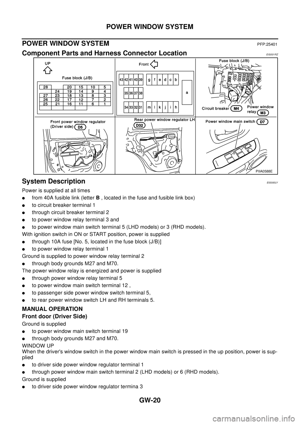
Component Parts and Harness Connector LocationEIS001RZ
System DescriptionEIS0 00 LY
Power is supplied at all times
lfrom 40A fusible link (letterB, located in the fuse and fusible link box)
lto circuit breaker terminal 1
lthrough circuit breaker terminal 2
lto power window relay terminal 3 and
lto power window main switch terminal 5 (LHD models) or 3 (RHD models).
With ignition switch in ON or START position, power is supplied
lthrough 10A fuse [No. 5, located in the fuse block (J/B)]
lto power window relay terminal 1
Ground is supplied to power window relay terminal 2
lthrough body grounds M27 and M70.
The power window relay is energized and power is supplied
lthrough power window relay terminal 5
lto power window main switch terminal 12 ,
lto passenger side power window switch terminal 5,
lto rear power window switch LH and RH terminals 5.
MANUAL OPERATION
Front door (Driver Side)
Ground is supplied
lto power window main switch terminal 19
lthrough body grounds M27 and M70.
WINDOW UP
When the driver's window switch in the power window main switch is pressed in the up position, power is sup-
plied
lto driver side power window regulator terminal 1
lthrough power window main switch terminal 2 (LHD models) or 6 (RHD models).
Ground is supplied
lto driver side power window regulator termina 3
PIIA0588E
Page 2341 of 3066

GW-38
POWER WINDOW SYSTEM
Trouble Diagnoses
EIS001SF
3 R/W Power window DOWN signalPower window switch DOWN
operation.Approx. 0
Power window switch
UP operation.Approx. 0
Power window switch DOWN
operation.Battery voltage
Power window switch
UP operation.Battery voltage
Other than above. Approx. 0
4 L/OR Power window UP signalPower window switch
UP operation.Approx. 0
Power window switch DOWN
operation.Approx. 0
Power window switch
UP operation.Battery voltage
Power window switch DOWN
operation.Battery voltage
Other than above. Approx. 0
5W/RPower window switch power
supply— Battery voltage TERMINALWIRE
COLORITEM CONDITION VOLTAGE (V)
Symptom Possible cause Repair order
None of the power windows can be
operated using any switch.1. 10A fuse, 40A fusible link
2. M4 circuit breaker
3. Power window relay
4. M4 circuit breaker
5. Ground circuit
6. Power window main switch1. Check 10A fuse [No. 5, located in fuse block (J/B)]
Turn ignition switch “ON” and verify positive battery
voltage is present at terminal 1 (G) of power window
relay.
2. Check 40A fusible link (letterB, located in fuse and
fusible link box) and M4 circuit breaker. Verify positive
battery voltage is present at terminal 3 (W) of power
window relay.
3. Check M4 circuit breaker.
4. Check power window relay.
5. Check the following:
–Check harness between M4 circuit breaker and 40A
fusible link (letterB,located in fuse and fusible link
box).
–Check harness between M4 circuibt breaker and
power window main switch terminal 5 (LHD models)
or 3 (RHD models)
6. Check the following
–Check ground circuit of power window main switch.
–Check power window relay ground circuit.
–Check power window main switch.
Driver side power window cannot be
operated but other windows can be
operated.1. Driver side power window regula-
tor circuit
2. Driver side power window regula-
tor
3. Power window main switch1. Check harness between power window main switch
and driver side power window regulator for open or
short circuit.
2. Check driver side power window regulator.
3. Check power window main switch.
Page 2362 of 3066

IDX-5
A
C
D
E
F
G
H
I
J
K
L B
IDX
ALPHABETICAL INDEX
Front washer ......................................................WW-4
Front wiper .........................................................WW-4
FTS - Wiring diagram ......................................EC-752
Fuel check valve ..............................................EC-372
Fuel cut control (at no load high engine speed)EC-28,
EC-393
,EC-662
Fuel filler lid ........................................................BL-64
Fuel filter ..........................................................EC-664
Fuel filter replacement(QR20DE) .........................FL-4
Fuel filter replacement(YD22DDTi) .......FL-15,MA-30
Fuel gauge ..................................................DI-4,DI-22
Fuel injection control system ...........................EC-660
Fuel injection system .........................EC-194,EC-200
Fuel injector .....................................................EC-727
Fuel injector adjustment resistor ......................EC-777
Fuel injector and fuel tube(QR20DE) ................EM-29
Fuel injector and fuel tube(YD22DDTi) ............EM-135
Fuel leak ..........................................................EC-781
Fuel line inspection(QR20DE) .................FL-3,MA-23
Fuel line inspection(YD22DDTi) ............FL-14,MA-30
Fuel pressure check ............................EC-34,EC-399
Fuel pressure release ..........................EC-34,EC-399
Fuel pressure relief valve ................................EC-665
Fuel pump ..........................................EC-352,EC-627
Fuel pump and gauge(QR20DE) ..........................FL-4
Fuel system(QR20DE) .........................................FL-3
Fuel system(YD22DDTi) .....................................FL-14
Fuel tank(QR20DE) ..............................................FL-9
Fuel tank(YD22DDTi) .........................................FL-21
Fuel temperature sensor .................................EC-751
Fuse ...................................................................PG-12
Fuse and fusible link box ...................................PG-77
Fusible link .........................................................PG-12
G
Gear components (M/T) .......................MT-19
,MT-24
Generator ..........................................................SC-12
Generator - See Alternator ................................SC-12
Generic scan tool (GST) ....................................EC-96
Glass ..................................................GW-41,GW-43
GLOW - Wiring diagram ..................................EC-797
Glow plug .........................................................EC-796
Glow plug(YD22DDTi) .....................................EM-130
Glow relay ........................................................EC-796
Grease ...............................................................MA-17
Grille - See Exterior .............................................EI-11
Ground distribution ............................................PG-13
G-sensor .............................................................TF-50
H
H/AIM - Wiring diagram ......................................LT-15
H/LAMP - Wiring diagram ...........................LT-4,LT-5
H/MIRROR - Wiring diagram ............................GW-10
Harness connector ............................................PG-70
Harness layout ...................................................PG-29
Headlamp .............................................................LT-4
Headlamp aiming control ....................................LT-15
Headlamp leveler - See Headlamp aiming control .......
LT-15
Headlamp washer ............................................WW-19
Headlining - See Roof trim ..................................EI-29
Heated oxygen sensor 1 ....EC-160,EC-166,EC-174,
EC-284
,EC-290,EC-490,EC-581
Heated oxygen sensor 1 heater .........EC-120,EC-568
Heated oxygen sensor 2 ....EC-181,EC-187,EC-296,
EC-303
,EC-587
Heated oxygen sensor 2 heater .........EC-125,EC-573
Heated seat ...............................................SE-3,SE-5
HEATER - Wiring diagram ................................MTC-6
Heater and cooling unit (Heater core) ............ATC-115
Heater mirror .....................................................GW-10
Heater system - Wiring diagram .......................MTC-6
Heater unit (heater core) ..ATC-120,MTC-23,MTC-26
HFC134a (R134a) system precaution ...............ATC-4
HFC134a (R134a) system service procedureATC-123
HFC134a (R134a) system service tools ..........ATC-12
HFC134a system service equipment precautionATC-8
HO2S1 - Wiring diaram ......EC-122,EC-162,EC-169,
EC-177
,EC-492
HO2S2 - Wiring diagram ....EC-183,EC-190,EC-299,
EC-306
HO2S2H - Wiring diagram ...............................EC-127
Hood ....................................................................BL-4
Horn .................................................................WW-23
HORN - Wiring diagram ...................................WW-23
How to erase DTC ...........................................EC-666
HowtoeraseDTCforOBDsystem .....EC-46,EC-402
I
IATS - Wiring diagram .....................................EC-138
IATSEN - Wiring diagram ................................EC-578
Identification .....................................................ATC-10
Idle air volume learning ........................EC-31,EC-396
Idle speed .............................EC-64,EC-412,EC-672
IGN/SG - Wiring diagram .................................EC-335
Ignition coil .........................................EC-334,EC-592
Ignition coil(QR20DE) .......................................EM-27
Ignition control system .......................EC-334,EC-592
Ignition timing .......................................EC-64,EC-412
IGNSYS - Wiring diagram ................................EC-593
ILL - Wiring diagram ...........................................LT-45
Illumination ..........................................................LT-45
In vehicle sensor ...............ATC-95,ATC-97,ATC-106
INJECT - Wiring diagram ....EC-344,EC-619,EC-730
Injection nozzle(YD22DDTi) ...........................EM-135
Injector ...............................................EC-343,EC-618
Input shaft (FF M/T) ..............................MT-19,MT-24
Instrument panel ...................................................IP-3
INT/L - Wiring diagram ........................................LT-65
Intake air temparature sensor ............EC-136,EC-577
Intake door control linkage adjustment ............ATC-66
Intake door motorATC-64,ATC-112,MTC-10,MTC-22
Intake manifold(QR20DE) .................................EM-17
Page 2402 of 3066

LT-4
HEADLAMP
HEADLAMP
PFP:26010
System DescriptionEKS003CD
DESCRIPTION
The headlamps are controlled by the lighting switch which is built into the combination switch.
Power is supplied at all times
lto lighting switch terminal 8
lthrough 15A fuse (No. 40, located in the fuse and fusible link box), and
lto lighting switch terminal 5
lthrough 15A fuse (No. 41, located in the fuse and fusible link box).
LOW BEAM OPERATION
When the lighting switch is turned to the 2ND position and placed in LOW (“B”) position, power is supplied
lfrom lighting switch terminal 10
lto terminal 3 of the headlamp LH, and
lfrom lighting switch terminal 7
lto terminal 3 of the headlamp RH.
Terminal 2 of each headlamp supplies ground through body grounds E24 and E50.
With power and ground supplied, the low beams will illuminate.
HIGH BEAM OPERATION/FLASH-TO-PASS OPERATION
When the lighting switch is turned to the 2ND position and placed in HIGH (“A”) position or PASS (“C”) posi-
tion, power is supplied
lfrom lighting switch terminal 6
lto terminal 1 of headlamp RH, and
lfrom lighting switch terminal 9
lto terminal 1 of headlamp LH, and
lto combination meter terminal 61 (LHD models) or 50 (RHD models) for the HIGH BEAM indicator.
Ground is supplied to terminal 60 (LHD models) or 49 (RHD models) of the combination meter through body
grounds M27 and M70.
Ground is supplide to terminal 2 of each headlamp through body grounds E24 and E50.
With power and ground supplied, the high beams and the HIGH BEAM indicator illuminate.
Page 2404 of 3066

LT-6
HEADLAMP
Trouble Diagnoses
EKS003CF
Aiming AdjustmentEKS003CG
When performing headlamp aiming adjustment, use an aiming machine, aiming wall screen or headlamp
tester. Aimers should be in good repair, calibrated and operated in accordance with respective operation man-
uals.
If any aimer is not available, aiming adjustment can be done as follows:
For details, refer to the regulations in your own country.
lKeep all tires inflated to correct pressures.
lPlace vehicle and tester on one and same flat surface.
lSee that there is no-load in vehicle (coolant, engine oil filled up to correct level and full fuel tank) other
than the driver (or equivalent weight placed in driver's position).
Symptom Possible cause Repair order
Headlamp LH do not operate.1. Bulb
2. Grounds E24 and E50
3. 15A fuse
4. Lighting switch1. Check bulb.
2. Check grounds E24 and E50.
3. Check 15A fuse (No. 40, located in fuse
and fusible link box). Verify battery posi-
tive voltage is present at terminal 8 of
lighting switch.
4. Check lighting switch.
Headlamp RH do not operate.1. Bulb
2. Grounds E24 and E50
3. 15A fuse
4. Lighting switch1. Check bulb.
2. Check grounds E24 and E50.
3. Check 15A fuse (No. 41, located in fuse
and fusible link box). Verify battery posi-
tive voltage is present at terminal 5 of
lighting switch.
4. Check lighting switch.
High beam LH do not operate, but low
beam LH operates.1. Bulb
2. Open in high beam LH circuit
3. Lighting switch1. Check bulbs.
2. Check the wire between lighting switch
terminal 9 and headlamp LH terminal 1
for an open circuit.
3. Check lighting switch.
Low beam LH does not operate, but high
beam LH operates.1. Bulb
2. Open in low beam LH circuit
3. Lighting switch1. Check bulb.
2. Check the wire between lighting switch
terminal 10 and headlamp LH terminal 3
for an open circuit.
3. Check lighting switch.
High beam RH do not operate, but low
beam RH operates.1. Bulb
2. Open in high beam RH circuit
3. Lighting switch1. Check bulbs.
2. Check the wire between lighting switch
terminal 6 and headlamp RH terminal 1
for an open circuit.
3. Check lighting switch.
Low beam RH does not operate, but high
beam RH operates.1. Bulb
2. Open in low beam RH circuit
3. Lighting switch1. Check bulb.
2. Check the wire between lighting switch
terminal 7 and headlamp RH terminal 3
for an open circuit.
3. Check lighting switch.
High beam indicator does not work.1. Bulb
2. Grounds M27 and M70
3. Open in high beam circuit1. Check bulb in combination meter.
2. Check grounds M27 and M70.
3. Check the wire between lighting switch
terminal 9 and combination meter termi-
nal 61(LHD models) or 50(RHD models)
for an open circuit.
Page 2407 of 3066

HEADLAMP - DAYTIME LIGHT SYSTEM -
LT-9
C
D
E
F
G
H
I
J
L
MA
B
LT
HEADLAMP - DAYTIME LIGHT SYSTEM -PFP:26010
System DescriptionEKS003BB
DESCRIPTION
The headlamp system on vehicles for North Europe contains a daytime light unit. The unit activates the follow-
ing whenever the engine is running with the lighting switch in the OFF position:
lLow beam headlamps
lParking, license, tail and illumination lamps
Power is supplied at all times
lthrough 10A fuse (No. 31, located in the fuse and fusible link box)
lto daytime light unit terminal 1 and
lto lighting switch terminal 11.
Power is also supplied at all times
lthrough 15A fuse (No. 41, located in the fuse and fusible link box)
lto daytime light unit terminal 3 and
lto lighting switch terminal 5.
Power is also supplied at all times
lthrough 15A fuse (No. 40, located in the fuse and fusible link box)
lto daytime light unit terminal 2 and
lto lighting switch terminal 8.
With the ignition switch in the ON or START position, power is supplied
lthrough 10A fuse [No. 13, located in the fuse block (J/B)]
lto daytime light unit terminal 7.
With the ignition switch in the START position, power is supplied
lthrough 10A fuse [No. 7, located in the fuse block (J/B)]
lto daytime light unit terminal 6.
HEADLAMP OPERATION (DAYTIME LIGHT CANCEL OPERATION)
When the lighting switch is turned to the 1st or 2nd position, power is supplied
lthrough lighting switch terminal 12,
lto daytime light unit terminal 11.
Then daytime light will be canceled. And the lighting system operation will be the same as no daytime light
system.
DAYTIME LIGHT OPERATION
With the engine running and the lighting switch in the OFF position, power is supplied
lfrom alternator terminal 3
lto daytime light unit terminal 8,
lthrough daytime light unit terminal 5
lto terminal 3 of headlamp LH,
lthrough daytime light unit terminal 4
lto terminal 3 of headlamp RH and
lthrough daytime light unit terminal 10
lto tail lamp and illumination.
Ground is supplied to terminal 2 of each headlamp through body grounds E24 and E50.
Page 2415 of 3066

TURN SIGNAL AND HAZARD WARNING LAMPS
LT-17
C
D
E
F
G
H
I
J
L
MA
B
LT
TURN SIGNAL AND HAZARD WARNING LAMPSPFP:26120
System DescriptionEKS003BX
TURN SIGNAL OPERATION
With the hazard switch in the OFF position and the ignition switch in the ON or START position, power is sup-
plied
lthrough 10A fuse [No. 2, located in the fuse block (J/B)]
lto hazard switch terminal 2
lthrough terminal 1 of the hazard switch
lto combination flasher unit terminal 1
lthrough terminal 3 of the combination flasher unit
lto turn signal switch terminal 1.
Ground is supplied to combination flasher unit terminal 2 through body grounds M27 and M70.
LH Turn
When the turn signal switch is moved to the LH position, power is supplied from turn signal switch terminal 3 to
lfront turn signal lamp LH terminal 1
lside turn signal lamp LH terminal 1
lcombination meter terminal 57 (LHD models) or 12 (RHD models)
lrear combination lamp LH terminal 2.
Ground is supplied to the front turn signal lamp LH terminal 2 through body grounds E24 and E50.
Ground is supplied to the side turn signal lamp LH terminal 2 through body grounds E24 and E50.
Ground is supplied to the rear combination lamp LH terminal 2 through body grounds B8 and B18.
Ground is supplied to combination meter terminal 48 (LHD models) or 61 (RHD models) through body
grounds M27 and M70.
With power and ground supplied, the combination flasher unit controls the flashing of the LH turn signal lamps.
RH Turn
When the turn signal switch is moved to the RH position, power is supplied from turn signal switch terminal 2
to
lfront turn signal lamp RH terminal 1
lside turn signal lamp RH terminal 1
lcombination meter terminal 12 (LHD models) or 46 (RHD models)
lrear combination lamp RH terminal 2.
Ground is supplied to the front turn signal lamp RH terminal 2 through body grounds E24 and E50.
Ground is supplied to the side turn signal lamp RH terminal 2 through body grounds E24 and E50.
Ground is supplied to the rear combination lamp RH terminal 2 through body grounds B8 and B18.
Ground is supplied to combination meter terminal 48 (LHD models) or 61 (RHD models) through body grounds
M27 and M70.
With power and ground supplied, the combination flasher unit controls the flashing of the RH turn signal
lamps.
HAZARD LAMP OPERATION
Power is supplied at all times to hazard switch terminal 3 through:
l10A fuse (No. 35, located in the fuse and fusible link box).
With the hazard switch in the ON position, power is supplied
lthrough terminal 1 of the hazard switch
lto combination flasher unit terminal 1
lthrough terminal 3 of the combination flasher unit
lto hazard switch terminal 4.
Ground is supplied to combination flasher unit terminal 2 through body grounds M27 and M70.
Power is supplied through terminal 6 of the hazard switch to
lfront turn signal lamp LH terminal 1
lcombination meter terminal 57 (LHD models) or 12 (RHD models)