2003 NISSAN X-TRAIL fuse box
[x] Cancel search: fuse boxPage 2419 of 3066
TURN SIGNAL AND HAZARD WARNING LAMPS
LT-21
C
D
E
F
G
H
I
J
L
MA
B
LT
Trouble DiagnosesEKS003BG
Electrical Components InspectionEKS0034C
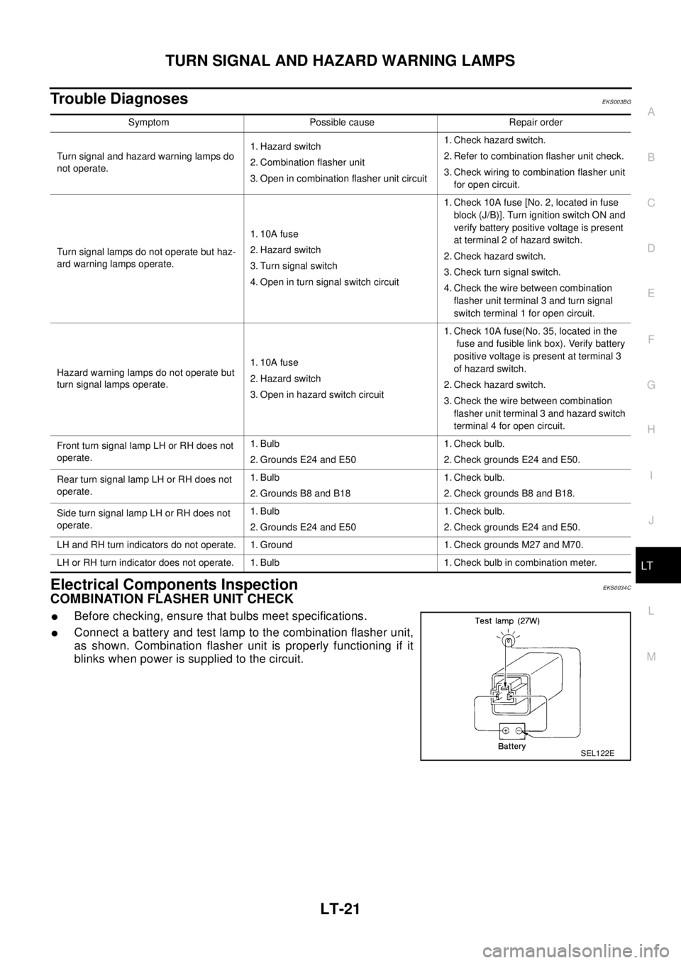
COMBINATION FLASHER UNIT CHECK
lBefore checking, ensure that bulbs meet specifications.
lConnect a battery and test lamp to the combination flasher unit,
as shown. Combination flasher unit is properly functioning if it
blinks when power is supplied to the circuit.
Symptom Possible cause Repair order
Turn signal and hazard warning lamps do
not operate.1. Hazard switch
2. Combination flasher unit
3. Open in combination flasher unit circuit1. Check hazard switch.
2. Refer to combination flasher unit check.
3. Check wiring to combination flasher unit
for open circuit.
Turn signal lamps do not operate but haz-
ard warning lamps operate.1. 10A fuse
2. Hazard switch
3. Turn signal switch
4. Open in turn signal switch circuit1. Check 10A fuse [No. 2, located in fuse
block (J/B)]. Turn ignition switch ON and
verify battery positive voltage is present
at terminal 2 of hazard switch.
2. Check hazard switch.
3. Check turn signal switch.
4. Check the wire between combination
flasher unit terminal 3 and turn signal
switch terminal 1 for open circuit.
Hazard warning lamps do not operate but
turn signal lamps operate.1. 10A fuse
2. Hazard switch
3. Open in hazard switch circuit1. Check 10A fuse(No. 35, located in the
fuse and fusible link box). Verify battery
positive voltage is present at terminal 3
of hazard switch.
2. Check hazard switch.
3. Check the wire between combination
flasher unit terminal 3 and hazard switch
terminal 4 for open circuit.
Front turn signal lamp LH or RH does not
operate.1. Bulb
2. Grounds E24 and E501. Check bulb.
2. Check grounds E24 and E50.
Rear turn signal lamp LH or RH does not
operate.1. Bulb
2. Grounds B8 and B181. Check bulb.
2. Check grounds B8 and B18.
Side turn signal lamp LH or RH does not
operate.1. Bulb
2. Grounds E24 and E501. Check bulb.
2. Check grounds E24 and E50.
LH and RH turn indicators do not operate. 1. Ground 1. Check grounds M27 and M70.
LH or RH turn indicator does not operate. 1. Bulb 1. Check bulb in combination meter.
SEL122E
Page 2431 of 3066
FRONT FOG LAMP
LT-33
C
D
E
F
G
H
I
J
L
MA
B
LT
FRONT FOG LAMPPFP:00011
System DescriptionEKS003DF
DESCRIPTION
Power is supplied at all times to fog lamp relay terminal 3
lthrough 15A fuse (No. 42, located in the fuse and fusible link box).
With the lighting switch in the 2ND position and LOW (“B”) position, power is supplied
lthrough 10A fuse (No. 31, located in the fuse and fusible link box).
lto lighting switch terminal 11
lthrough terminal 12 of the lighting switch
lto fog lamp switch terminal 32
lthroughterminal31ofthefoglampswitch
lto fog lamp relay terminal 2.
FOG LAMP OPERATION
The fog lamp switch is built into the combination switch. The lighting switch must be in the 1st or 2nd position
and LOW (“B”) position for fog lamp operation.
With the fog lamp switch in the ON position, ground is supplied
lto fog lamp relay terminal 1
lthrough the fog lamp switch and body grounds E24 and E50.
The fog lamp relay is energized and power is supplied
lfrom fog lamp relay terminal 5
lto terminal 1 of each fog lamp.
Ground is supplied to terminal 2 of each fog lamp through body grounds E24 and E50.
With power and ground supplied, the fog lamps illuminate.
Page 2443 of 3066
![NISSAN X-TRAIL 2003 Electronic Repair Manual ILLUMINATION
LT-45
C
D
E
F
G
H
I
J
L
MA
B
LT
ILLUMINATIONPFP:27545
System DescriptionEKS003C7
Power is supplied at all times
lthrough 10A fuse [No. 31, located in the fuse and fusible link box]
lto li NISSAN X-TRAIL 2003 Electronic Repair Manual ILLUMINATION
LT-45
C
D
E
F
G
H
I
J
L
MA
B
LT
ILLUMINATIONPFP:27545
System DescriptionEKS003C7
Power is supplied at all times
lthrough 10A fuse [No. 31, located in the fuse and fusible link box]
lto li](/manual-img/5/57402/w960_57402-2442.png)
ILLUMINATION
LT-45
C
D
E
F
G
H
I
J
L
MA
B
LT
ILLUMINATIONPFP:27545
System DescriptionEKS003C7
Power is supplied at all times
lthrough 10A fuse [No. 31, located in the fuse and fusible link box]
lto lighting switch terminal 11.
The lighting switch must be in the 1ST or 2ND position for illumination.
The following chart shows the power and ground connector terminals for the components included in the illu-
mination system.
Component Connector No. Power terminal Ground terminal
Headlamp washier switch M23 3 4
Headlamp aiming switch M24 3 4
Door mirror remote control
switchM26 10 1
VDC off switch M25 3 4
Hazard switch M51 7 8
4WD mode switch M39 4 3
Rear window defogger switch M50 5 6
A/C auto amp. M52 12 11
Combination meter
(LHD models)M46 56 66
Combination meter
(RHD models)M46 45 56
Audio M42 2 1
CD auto changer M82 34 35
Heater control panel M55 2 6
A/T device M58 3 4
Cigarette lighter M56 3 2
Heated seat switch LH
(LHD models)B131 5 6
Heated seat switch RH
(LHD models)B132 5 6
Heated seat switch LH
(RHD models)B35 5 6
Heated seat switch RH
(RHD models)B34 5 6
Page 2496 of 3066
MA-4
DESCRIPTION
DESCRIPTION
PFP:00000
Pre-delivery Inspection ItemsELS000AK
Shown below are Pre-delivery Inspection Items required for the new vehicle. It is recommended that
necessary items other than those listed here be added, paying due regard to the conditions in each
country.
Perform applicable items on each model. Consult text of this section for specifications.
UNDER HOOD — engine off
Radiator coolant level and coolant hose connections for leaks
Battery fluid level, specific gravity and conditions of battery terminals
Drive belts tension
Fuel filter for water or dusts (Diesel only), and fuel lines and connections for leaks
Engine oil level and oil leaks
Clutch and brake reservoir fluid level and fluid lines for leaks
Windshield and rear window washer and headlamp cleaner reservoir fluid level
Power steering reservoir fluid level and hose connections for leaks
ON INSIDE AND OUTSIDE
Remove front spring/strut spacer (If applicable)
Operation of all instruments, gauges, lights and accessories
Operation of horn(s), wiper and washer
Steering lock for operation
Check air conditioner for gas leaks
Front and rear seats, and seat belts for operation
All moldings, trims and fittings for fit and alignment
All windows for operation and alignment
Hood, trunk lid, door panels for fit and alignment
Latches, keys and locks for operation
Weatherstrips for adhesion and fit
Headlamp aiming
Tighten wheel nuts (Inc. inner nuts if applicable)
Tire pressure (Inc. spare tire)
Check front wheels for toe-in
Install clock/voltmeter/room lamp fuse (If applicable)
Install deodorizing filter to air conditioner (If applicable)
Remove wiper blade protectors (If applicable)
UNDER BODY
Manual transmission/transaxle, transfer and differential gear oil level
Brake and fuel lines and oil/fluid reservoirs for leaks
Tighten bolts and nuts of steering linkage and gear box, suspension, propeller shafts and drive shafts
Tighten rear body bolts and nuts (Models with wooden bed only)
ROAD TEST
Clutch operation
Parking brake operation
Service brake operation
Automatic transmission/transaxle shift timing and kickdown
Steering control and returnability
Engine performance
Squeaks and rattles
ENGINE OPERATING AND HOT
Adjust idle speed
Automatic transmission/transaxle fluid level
Page 2657 of 3066
BLOWER FAN RESISTOR
MTC-21
C
D
E
F
G
H
I
K
L
MA
B
MTC
BLOWER FAN RESISTORPFP:27150
Removal and InstallationEJS000XL
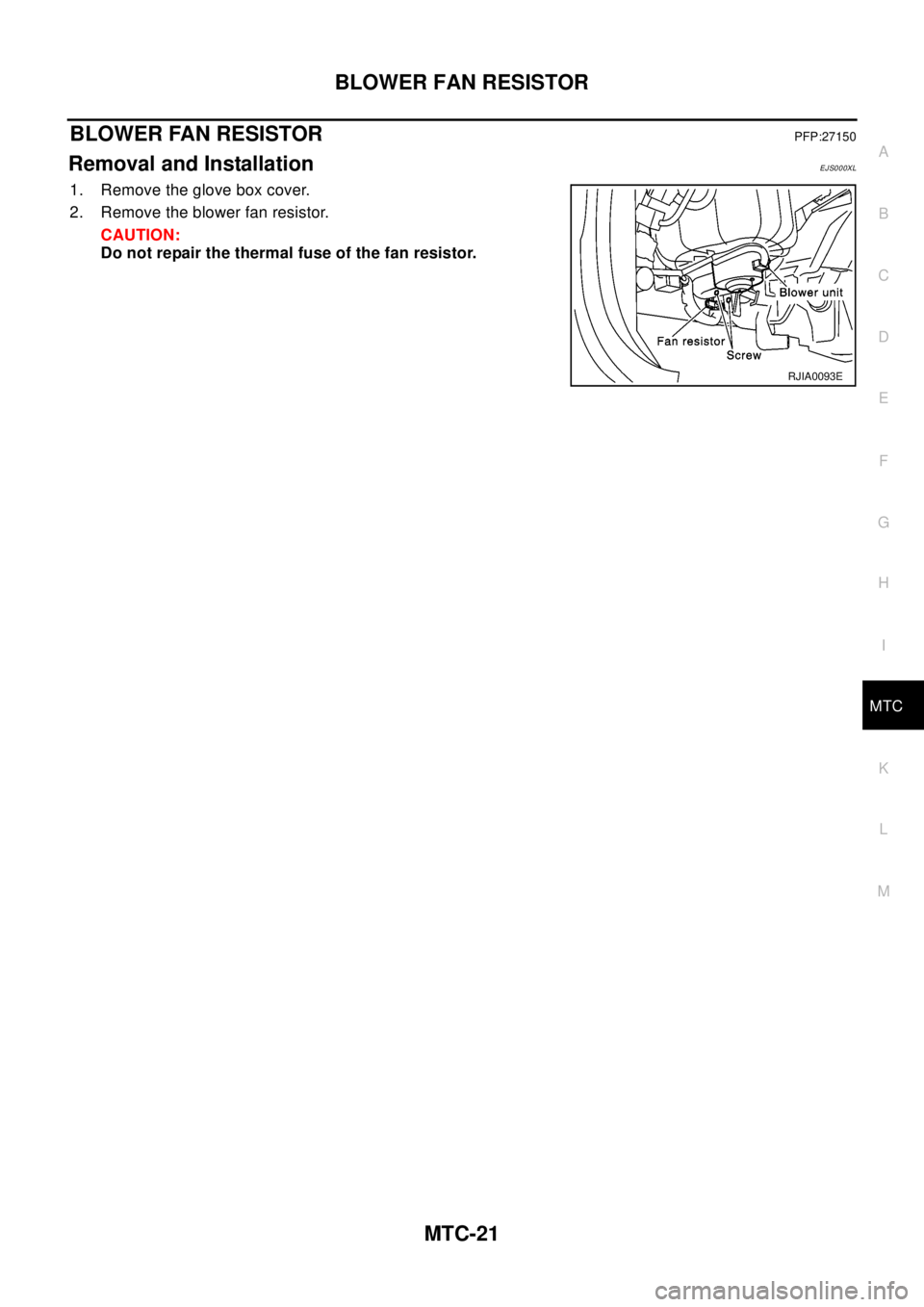
1. Remove the glove box cover.
2. Remove the blower fan resistor.
CAUTION:
Do not repair the thermal fuse of the fan resistor.
RJIA0093E
Page 2677 of 3066
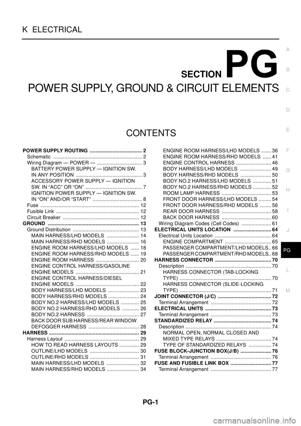
PG-1
POWER SUPPLY, GROUND & CIRCUIT ELEMENTS
K ELECTRICAL
CONTENTS
C
D
E
F
G
H
I
J
L
M
SECTION
A
B
PG
POWER SUPPLY, GROUND & CIRCUIT ELEMENTS
POWER SUPPLY ROUTING ...................................... 2
Schematic ................................................................ 2
Wiring Diagram — POWER — ................................. 3
BATTERY POWER SUPPLY — IGNITION SW.
IN ANY POSITION ................................................ 3
ACCESSORY POWER SUPPLY — IGNITION
SW. IN “ACC” OR “ON” ......................................... 7
IGNITION POWER SUPPLY — IGNITION SW.
IN “ON” AND/OR “START” .................................... 8
Fuse ....................................................................... 12
Fusible Link ............................................................ 12
Circuit Breaker ....................................................... 12
GROUND .................................................................. 13
Ground Distribution ................................................ 13
MAIN HARNESS/LHD MODELS ........................ 14
MAIN HARNESS/RHD MODELS ........................ 16
ENGINE ROOM HARNESS/LHD MODELS ....... 18
ENGINE ROOM HARNESS/RHD MODELS ....... 19
ENGINE ROOM HARNESS ................................ 20
ENGINE CONTROL HARNESS/GASOLINE
ENGINE MODELS .............................................. 21
ENGINE CONTROL HARNESS/DIESEL
ENGINE MODELS .............................................. 22
BODY HARNESS/LHD MODELS ....................... 23
BODY HARNESS/RHD MODELS ....................... 24
BODY NO.2 HARNESS/LHD MODELS .............. 25
BODY NO.2 HARNESS/RHD MODELS ............. 26
BODY NO.2 HARNESS ...................................... 27
BACK DOOR SUB HARNESS/REAR WINDOW
DEFOGGER HARNESS ..................................... 28
HARNESS ................................................................. 29
Harness Layout ...................................................... 29
HOW TO READ HARNESS LAYOUTS ............... 29
OUTLINE/LHD MODELS .................................... 30
OUTLINE/RHD MODELS .................................... 31
MAIN HARNESS/LHD MODELS ........................ 32
MAIN HARNESS/RHD MODELS ........................ 34ENGINE ROOM HARNESS/LHD MODELS ........ 36
ENGINE ROOM HARNESS/RHD MODELS ....... 41
ENGINE CONTROL HARNESS .......................... 46
BODY HARNESS/LHD MODELS ....................... 49
BODY HARNESS/RHD MODELS ....................... 50
BODY NO.2 HARNESS/LHD MODELS .............. 51
BODY NO.2 HARNESS/RHD MODELS .............. 52
ROOM LAMP HARNESS .................................... 53
FRONT DOOR HARNESS/LHD MODELS .......... 54
FRONT DOOR HARNESS/RHD MODELS ......... 56
REAR DOOR HARNESS .................................... 58
BACK DOOR HARNESS .................................... 60
Wiring Diagram Codes (Cell Codes) ...................... 61
ELECTRICAL UNITS LOCATION ............................ 64
Electrical Units Location ......................................... 64
ENGINE COMPARTMENT .................................. 65
PASSENGER COMPARTMENT/LHD MODELS... 66
PASSENGER COMPARTMENT/RHD MODELS... 68
HARNESS CONNECTOR ......................................... 70
Description .............................................................. 70
HARNESS CONNECTOR (TAB-LOCKING
TYPE) .................................................................. 70
HARNESS CONNECTOR (SLIDE-LOCKING
TYPE) .................................................................. 71
JOINT CONNECTOR (J/C) ....................................... 72
Terminal Arrangement ............................................ 72
ELECTRICAL UNITS ................................................ 73
Terminal Arrangement ............................................ 73
STANDARDIZED RELAY .......................................... 74
Description .............................................................. 74
NORMAL OPEN, NORMAL CLOSED AND
MIXED TYPE RELAYS ........................................ 74
TYPE OF STANDARDIZED RELAYS ................. 74
FUSE BLOCK-JUNCTION BOX(J/B) ....................... 76
Terminal Arrangement ............................................ 76
FUSE AND FUSIBLE LINK BOX .............................. 77
Terminal Arrangement ............................................ 77
Page 2752 of 3066

PG-76
FUSE BLOCK-JUNCTION BOX(J/B)
FUSE BLOCK-JUNCTION BOX(J/B)
PFP:24350
Terminal ArrangementEKS0032F
CKWA0094E
Page 2753 of 3066
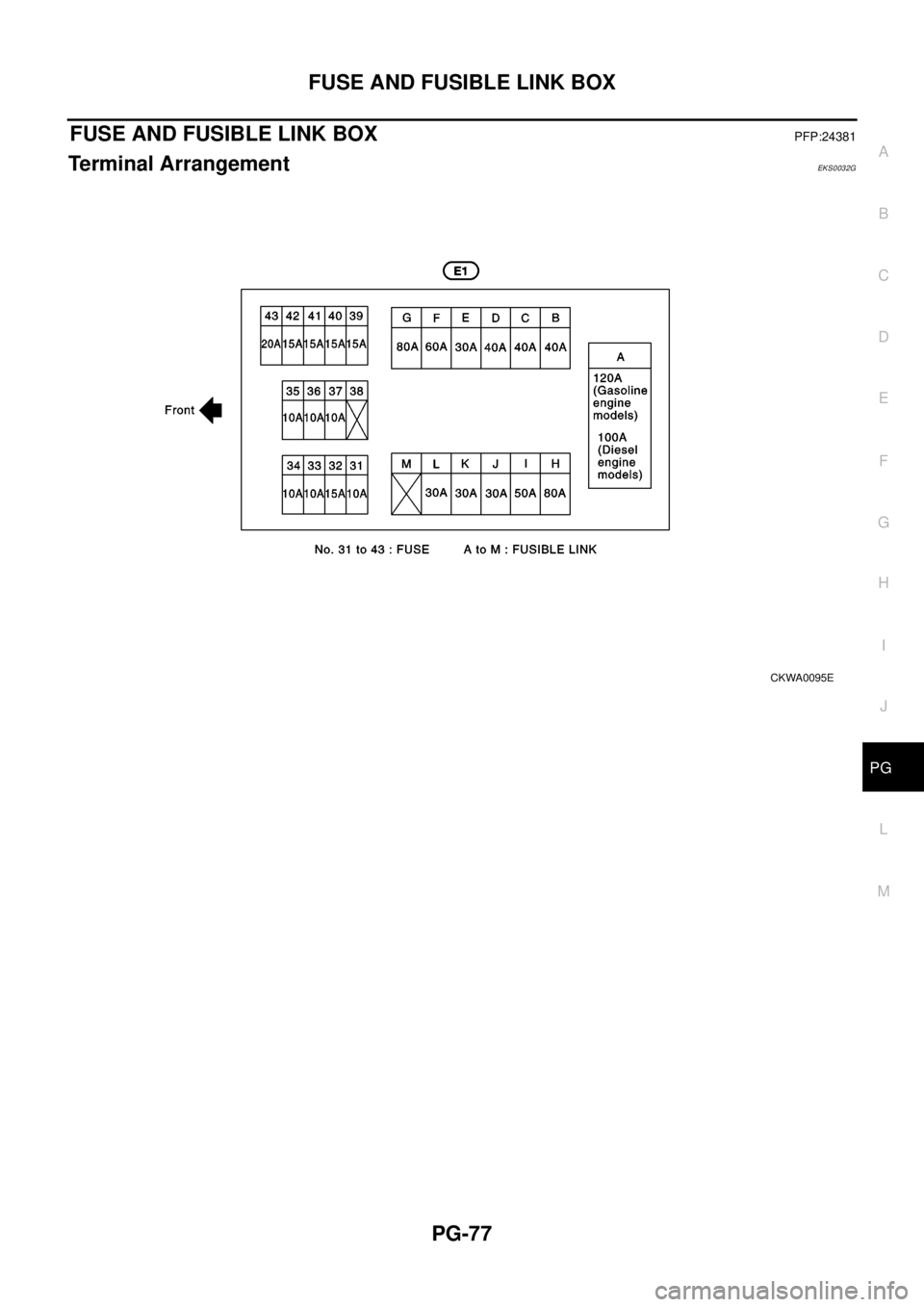
FUSE AND FUSIBLE LINK BOX
PG-77
C
D
E
F
G
H
I
J
L
MA
B
PG
FUSE AND FUSIBLE LINK BOXPFP:24381
Terminal ArrangementEKS0032G
CKWA0095E