2003 NISSAN X-TRAIL engine coolant
[x] Cancel search: engine coolantPage 2241 of 3066

FSU-2
PRECAUTIONS
PRECAUTIONS
PFP:00001
CautionEES0006Z
lWhen installing rubber bushings, final tightening must be carried out under unladen conditions with tires
on flat, level ground. Oil will shorten the life of rubber bushings. Be sure to wipe off any spilled oil.
l“Unladen condition” means that fuel, coolant and lubricant are full and ready for drive. However, spare tire,
jack, and hand tools should be unloaded.
lAfter installing the removed suspension parts, always check wheel alignment and adjust if necessary.
lReplace the caulking nut with a new one. Install a new nut without wiping the oil off before tightening.
Precautions for Brake SystemEES000JA
lWhen installing rubber parts, final tightening must be carried out
under unladen condition* with tires on ground.
*: Fuel, radiator coolant and engine oil full. Spare tire, jack,
hand tools and mats in designated positions.
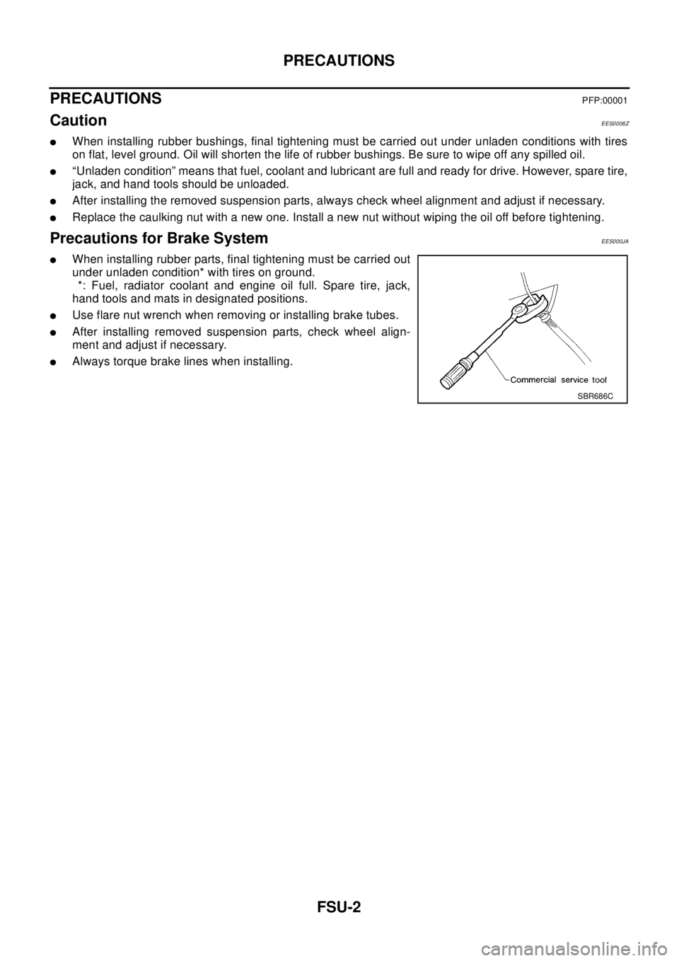
lUse flare nut wrench when removing or installing brake tubes.
lAfter installing removed suspension parts, check wheel align-
ment and adjust if necessary.
lAlways torque brake lines when installing.
SBR686C
Page 2252 of 3066

SERVICE DATA AND SPECIFICATIONS (SDS)
FSU-13
C
D
F
G
H
I
J
K
L
MA
B
FSU
SERVICE DATA AND SPECIFICATIONS (SDS)PFP:00030
General SpecificationEES000J6
Wheel Alignment (Unladen)EES00079
: Fuel, radiator coolant and engine oil full. Spare tire, jack, hand tools and mats in designated positions.
Ball JointEES0007A
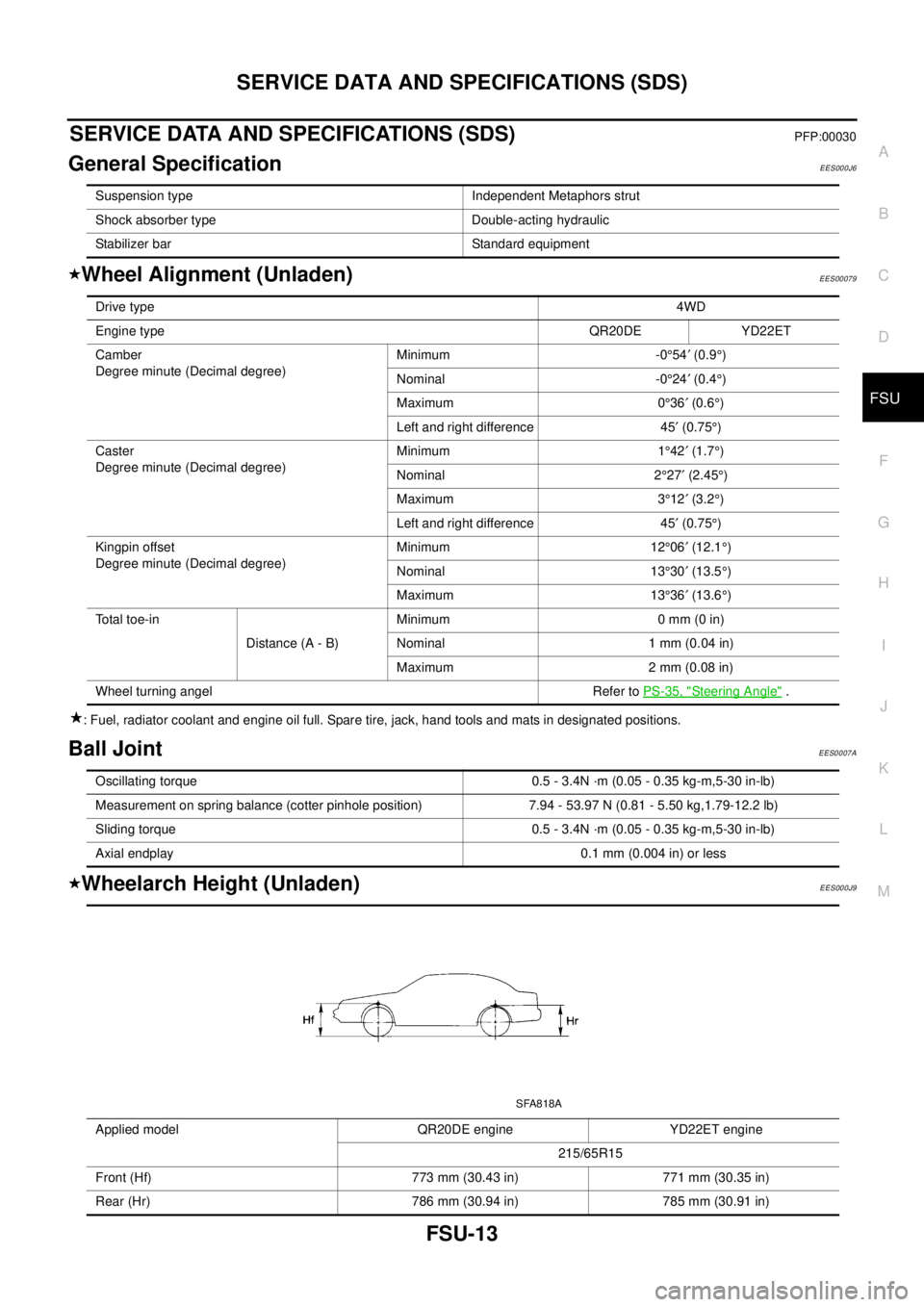
Wheelarch Height (Unladen)EES000J9
Suspension type Independent Metaphors strut
Shock absorber type Double-acting hydraulic
Stabilizer bar Standard equipment
Drive type4WD
Engine typeQR20DE YD22ET
Camber
Degree minute (Decimal degree)Minimum -0°54¢(0.9°)
Nominal -0°24¢(0.4°)
Maximum 0°36¢(0.6°)
Left and right difference 45¢(0.75°)
Caster
Degree minute (Decimal degree)Minimum 1°42¢(1.7°)
Nominal 2°27¢(2.45°)
Maximum 3°12¢(3.2°)
Left and right difference 45¢(0.75°)
Kingpin offset
Degree minute (Decimal degree)Minimum 12°06¢(12.1°)
Nominal 13°30¢(13.5°)
Maximum 13°36¢(13.6°)
To t a l t o e - i n
Distance (A - B)Minimum 0 mm (0 in)
Nominal 1 mm (0.04 in)
Maximum 2 mm (0.08 in)
Wheel turning angel Refer toPS-35, "
Steering Angle".
Oscillating torque 0.5 - 3.4N ·m (0.05 - 0.35 kg-m,5-30 in-lb)
Measurement on spring balance (cotter pinhole position) 7.94 - 53.97 N (0.81 - 5.50 kg,1.79-12.2 lb)
Sliding torque 0.5 - 3.4N ·m (0.05 - 0.35 kg-m,5-30 in-lb)
Axial endplay 0.1 mm (0.004 in) or less
Applied model QR20DE engine YD22ET engine
215/65R15
Front (Hf) 773 mm (30.43 in) 771 mm (30.35 in)
Rear (Hr) 786 mm (30.94 in) 785 mm (30.91 in)
SFA818A
Page 2253 of 3066

FSU-14
SERVICE DATA AND SPECIFICATIONS (SDS)
: Fuel, radiator coolant and engine oil full. Spare tire, jack, hand tools and mats in designated positions.
Page 2300 of 3066

TERMINOLOGY
GI-47
TERMINOLOGYPFP:00011
SAE J1930 Terminology ListEAS000GH
All emission related terms used in this publication in accordance with SAE J1930 are listed. Accordingly, new
terms, new acronyms/abbreviations and old terms are listed in the following chart.
NEW TERMNEW ACRONYM /
ABBREVIATIONOLD TERM
Air cleaner ACL Air cleaner
Barometric pressure BARO ***
Barometric pressure sensor-BCDD BAROS-BCDD BCDD
Camshaft position CMP ***
Camshaft position sensor CMPS Crank angle sensor
Canister *** Canister
Carburetor CARB Carburetor
Charge air cooler CAC Intercooler
Closed loop CL Closed loop
Closed throttle position switch CTP switch Idle switch
Clutch pedal position switch CPP switch Clutch switch
Continuous fuel injection system CFI system ***
Continuous trap oxidizer system CTOX system ***
Crankshaft position CKP ***
Crankshaft position sensor CKPS ***
Data link connector DLC ***
Data link connector for CONSULT-II DLC for CONSULT-II Diagnostic connector for CONSULT-II
Diagnostic test mode DTM Diagnostic mode
Diagnostic test mode selector DTM selector Diagnostic mode selector
Diagnostic test mode I DTM I Mode I
Diagnostic test mode II DTM II Mode II
Diagnostic trouble code DTC Malfunction code
Direct fuel injection system DFI system ***
Distributor ignition system DI system Ignition timing control
Early fuel evaporation-mixture heater EFE-mixture heater Mixture heater
Early fuel evaporation system EFE system Mixture heater control
Electrically erasable programmable read
only memoryEEPROM ***
Electronic ignition system EI system Ignition timing control
Engine control EC ***
Engine control module ECM ECCS control unit
Engine coolant temperature ECT Engine temperature
Engine coolant temperature sensor ECTS Engine temperature sensor
Engine modification EM ***
Engine speed RPM Engine speed
Erasable programmable read only memory EPROM ***
Evaporative emission canister EVAP canister Canister
Evaporative emission system EVAP system Canister control solenoid valve
Exhaust gas recirculation valve EGR valve EGR valve
Page 2360 of 3066

IDX-3
A
C
D
E
F
G
H
I
J
K
L B
IDX
ALPHABETICAL INDEX
Brake fluid level and line check ...........................BR-9
Brake hydraulic line ...........................................BR-11
Brake inspection ................................................MA-39
Brake lines and cables inspection .....................MA-39
Brake master cylinder ........................................BR-13
Brake pedal .........................................................BR-6
Brake switch ........................EC-329,EC-562,EC-810
BRK/SW - Wiring diagram ...EC-330,EC-564,EC-811
Bulb specifications ..............................................LT-67
Bumper, front .........................................................EI-6
Bumper, rear ..........................................................EI-9
C
Camshaft inspection(QR20DE) .........................EM-38
Camshaft inspection(YD22DDTi) ....................EM-150
Camshaft position sensor (CMPS) ..................EC-739
Camshaft position sensor (PHASE) ..EC-223,EC-507
Camshaft(QR20DE) ..........................................EM-33
Camshaft(YD22DDTi) ......................................EM-149
CAN - Wiring diagramEC-115,EC-461,LAN-6,LAN-12
CAN (Controller Area Network) .........AT-129,AT-351,
LAN-3
,LAN-5,LAN-11
CAN Communication ..........................................TF-53
CAN communicationEC-28,EC-114,EC-393,EC-460,
AT-129
,AT-351,BRC-53,BRC-59,BRC-90,BRC-108,
LAN-3
,LAN-5,LAN-11
Canister-See EVAP canister .............EC-374,EC-649
CHARGE - Wiring diagram ................................SC-13
Charging system ................................................SC-12
Chassis and body maintenance ........................MA-35
CHIME - Wiring diagram .....................................DI-54
CIGAR - Wiring diagram ..................................WW-25
Cigarette lighter ...............................................WW-25
Circuit breaker ...................................................PG-12
CKPS - Wiring diagram ...................................EC-736
Clearance lamp ........................................LT-4,LT-40
Clock ...................................................................DI-60
CLOCK - Wiring diagram ....................................DI-60
Closed loop control ..............................EC-25,EC-390
Clutch cover .......................................................CL-15
Clutch disc .........................................................CL-15
Clutch master cylinder .........................................CL-9
Clutch operating cylinder ...................................CL-11
Clutch pedal .........................................................CL-5
Clutch release bearing .......................................CL-13
Clutch release mechanism ................................CL-13
Clutch withdrawal lever ......................................CL-13
CMPS - Wiring diagram ...................................EC-741
Coil spring (rear) ...............................................RSU-8
Collision diagnosis ...........................................SRS-46
Combination meter .....................................DI-4,DI-22
Combination switch ................................LT-24,LT-44
Common rail fuel pressure sensor ...................EC-723
Component Location (auto A/C) .........ATC-31,MTC-4
Compression pressure(QR20DE) ......................EM-52
Compression pressure(YD22DDTi) .................EM-173
Compressor clutch removal and installation ..ATC-129
Compressor special service tool ......................ATC-11
Condenser .....................................................ATC-138
Connecting rod bearing clearance(QR20DE) ...EM-83
Connecting rod bearing clearance(YD22DDTi)EM-206
Connecting rod bushing clearance(QR20DE) ..EM-83
Connecting rod bushing clearance(YD22DDTi)EM-200
Connecting rod(QR20DE) .................................EM-82
Connecting rod(YD22DDTi) ..............EM-198,EM-202
Console box - See Instrument panel ..........IP-3,IP-10
CONSULT for engine ............EC-86,EC-434,EC-691
CONSUT for VDC ...........................................BRC-77
Control unit .....................................ATC-104,MTC-19
Control units (terminal arrangement) .................PG-73
Controller Area Network (CAN) ........AT-129,AT-351,
LAN-3
,LAN-5,LAN-11
Converter housing installation ...........AT-459,AT-556
COOL/F - Wiring diagram ...EC-315,EC-552,EC-763
Coolant mixture ratio .........................................MA-19
Coolant replacement(QR20DE) ........................MA-20
Coolant replacement(YD22DDTi) .....................MA-27
Cooling circuit (engine)(QR20DE) ......................CO-7
Cooling circuit (engine)(YD22DDTi) .................CO-28
Cooling fan control system(QR20DE) ...............CO-13
Cooling fan motor ..............................EC-324,EC-561
Cooling fan relay ................................EC-324,EC-561
Cooling fan(QR20DE) .......................................CO-13
Cooling fan(YD22DDTi) ....................................CO-34
Coupling sleeve (M/T) ...........................MT-19,MT-24
Cowl top ..............................................................EI-12
Cowl top cover ....................................................EI-12
Crankcase ventilation system ..........................EC-663
Crankcase ventilation system - See Positive crankcase
ventilation ...........................................EC-375
,EC-650
Crankshaft position sensor (POS) .....EC-217,EC-501
Crankshaft position sensor (TDC) ...................EC-734
Crankshaft(QR20DE) ........................................EM-65
Crankshaft(YD22DDTi) ...................................EM-200
CRFPS - Wiring diagram .................................EC-724
Cylinder block boring(QR20DE) .......................EM-86
Cylinder block boring(YD22DDTi) ...................EM-204
Cylinder block(QR20DE) ..................................EM-64
Cylinder block(YD22DDTi) ..............................EM-188
Cylinder head bolt tightening(QR20DE) ...........EM-54
Cylinder head bolt tightening(YD22DDTi) .......EM-175
Cylinder head gasket selection(YD22DDTi) ...EM-175
Cylinder head(QR20DE) ...................................EM-52
Cylinder head(YD22DDTi) ..............................EM-173
D
Data link connector ............................EC-371
,EC-646
Data link connector for Consult ...........EC-88,EC-435,
EC-691
Daytime light system .............................................LT-9
Daytime running light - See Daytime light systemLT-9
DEF - Wiring diagram .......................................GW-10
Desiccant Assembly .......................ATC-27,ATC-140
Diagnosis sensor unit .....................................SRS-39
Page 2361 of 3066

IDX-4
ALPHABETICAL INDEX
Diagnostic trouble code (DTC) ........................EC-666
Diagnostic trouble code (DTC) for OBD systemEC-12,
EC-38
,EC-379,EC-401,EC-654
Diagnostic trouble code (DTC) inspection priority chart
EC-61
,EC-410
Differential gear (FF M/T) .....................MT-22,MT-27
DLC - Wiring diagram ........................EC-371,EC-646
Door glass ...........................................GW-41,GW-43
Door glass Fitting Adjustment .............GW-41,GW-43
Door lock .................................................BL-54,BL-57
Door mirror ........................................................GW-46
Door trim .............................................................EI-23
Door, front ............................................................BL-8
Door, rear .............................................................BL-8
Drive belt inspection(QR20DE) .........................MA-20
Drive belt inspection(YD22DDTi) ......................MA-27
Drive belt(QR20DE) ..........................................EM-13
Drive belt(YD22DDTi) .....................................EM-110
Drive shaft (front) .............................................FAX-11
Drive shaft (rear) ...............................................RAX-9
Driver air bag ..................................................SRS-27
Dropping resistor (A/T) ......................AT-192,AT-442
DTC work support ..............................................EC-95
DTRL - Wiring diagram .........................................LT-9
Dual pressure switch ........ATC-16,ATC-81,ATC-138
Duct and grilles ...............................ATC-121,MTC-29
E
ECM input/output signal .......................EC-79
,EC-427
ECM power supplyEC-108,EC-256,EC-454,EC-530,
EC-700
ECM relay ........................................................EC-790
ECM/PW - Wiring diagram .................EC-257,EC-531
ECMRLY - Wiring diagram ..............................EC-791
ECTS - Wiring diagram .......EC-143,EC-472,EC-712
EDU - Wiring diagram ......................................EC-756
EGR function ...................................................EC-803
EGR volume control valve ...............................EC-803
EGRC/V - Wiring diagram ................................EC-805
Electric sun roof ...................................................RF-2
Electric throttle control actuator ........EC-271,EC-273,
EC-534
,EC-536
Electrical unit .....................................................PG-73
Electrical units location ......................................PG-64
Electronic drive unit (EDU) ..............................EC-754
Electronic fuel injection pump(YD22DDTi) .....EM-138
Electronic ignition (EI) system .............EC-27,EC-392
Engine control circuit diagramEC-77,EC-425,EC-683
Engine control component parts location ..........EC-73,
EC-421
Engine control module (ECM) ...........EC-249,EC-523,
EC-788
Engine control system diagram and chart ........EC-22,
EC-387
,EC-659
Engine coolant temperature sensor (ECTS) ...EC-141,
EC-470
,EC-711
Engine coolant(QR20DE) ...................................CO-9
Engine coolant(YD22DDTi) ..............................CO-30
Engine fail-safe system .......................EC-62,EC-411
Engine oil filter replacement(QR20DE) .............MA-24
Engine oil filter replacement(YD22DDTi) ..........MA-33
Engine oil replacement(QR20DE) ....................MA-24
Engine oil replacement(YD22DDTi) ..................MA-32
Engine oil(QR20DE) ............................................LU-7
Engine oil(YD22DDTi) .......................................LU-18
Engine removal(QR20DE) ................................EM-61
Engine removal(YD22DDTi) ...........................EM-184
EVAP canister purge volume control solenoid valve ....
EC-233
,EC-372,EC-601,EC-649
EVAP vapor lines inspection(QR20DE) ............MA-26
Evaporative emission (EVAP) systemEC-372,EC-647
Evaporator ....................................................ATC-139
Exhaust manifold(QR20DE) .............................EM-22
Exhaust manifold(YD22DDTi) .........................EM-119
Exhaust system ...................................................EX-2
Exhaust system inspection .....................EX-2,MA-35
Expansion valve ............................................ATC-140
ExteriorEI-13,EI-14,EI-16,EI-17,EI-18,EI-19,EI-21,
EI-22
F
F/FOG - Wiring diagram .........................LT-33
,LT-34
F/PUMP - Wiring diagram .................EC-354,EC-629
Fan control amp. .............................ATC-70,ATC-113
Fan switch ........................................ATC-27,MTC-17
FIAR - Wiring diagram .....................................EC-778
Final drive (FF M/T) ..............................MT-22,MT-27
Final drive disassembly ..................................RFD-11
Final drive removal and installation ................RFD-11
Finisher, interior - See Trim ......................EI-23,EI-25
Finisher, rear panel .............................................EI-22
Floor trim .............................................................EI-28
Fluid temperature sensor (A/T) ........................AT-141
Fluids ................................................................MA-17
Fluorescent leak detector .............................ATC-141
Flywheel (clutch) ................................................CL-15
Flywheel runout(QR20DE) ................................EM-89
Flywheel runout(YD22DDTi) ...........................EM-208
Fog lamp, front ...................................................LT-33
Fork rod (M/T) .......................................MT-21,MT-26
Freeze frame data ..............................EC-39,EC-402
FRO2 - Wiring diagram ....................................EC-582
FRO2/H - Wiring diagram ................................EC-569
Front bumper ........................................................EI-6
Front disc brake .................................................BR-21
Front door ............................................................BL-8
Front Door Trim ..................................................EI-23
Front fog lamp ....................................................LT-33
Front passenger air bag ..................................SRS-33
Front seat .............................................................SE-7
Front seat belt ......................................................SB-3
Front seat belt pre-tensioner .....SB-2,SRS-3,SRS-38
Front side air bag ............................................SRS-35
Front suspension ..............................................FSU-5
Page 2379 of 3066
![NISSAN X-TRAIL 2003 Electronic Repair Manual CAN COMMUNICATION
LAN-3
[CAN]
C
D
E
F
G
H
I
J
L
MA
B
LAN
CAN COMMUNICATIONPFP:23710
System DescriptionEKS001U3
CAN (Controller Area Network) is a serial communication line for real time application. I NISSAN X-TRAIL 2003 Electronic Repair Manual CAN COMMUNICATION
LAN-3
[CAN]
C
D
E
F
G
H
I
J
L
MA
B
LAN
CAN COMMUNICATIONPFP:23710
System DescriptionEKS001U3
CAN (Controller Area Network) is a serial communication line for real time application. I](/manual-img/5/57402/w960_57402-2378.png)
CAN COMMUNICATION
LAN-3
[CAN]
C
D
E
F
G
H
I
J
L
MA
B
LAN
CAN COMMUNICATIONPFP:23710
System DescriptionEKS001U3
CAN (Controller Area Network) is a serial communication line for real time application. It is an on-vehicle mul-
tiplex communication line with high data communication speed and excellent error detection ability. Many elec-
tronic control units are equipped onto a vehicle, and each control unit shares information and links with other
control units during operation (not independent). In CAN communication, control units are connected with 2
communication lines (CAN H line, CAN L line) allowing a high rate of information transmission with less wiring.
Each control unit transmits/receives data but selectively reads required data only.
FOR A/T MODELS
System diagram
Input/output signal chart
T: Transmit R: Receive
FOR M/T MODELS
System diagram
Input/output signal chart
T: Transmit R: Receive
SKIA0884E
Signals ECM TCM
Engine speed signal T R
Engine coolant temperature signal T R
Accelerator pedal position signal T R
A/T self-diagnosis signal R T
SKIA0885E
Signals ECMSteering wheel
angle sensor4WD control unitESP/ TCS / ABS
control unit
Engine speed signal T R R
Accelerator pedal position signal T R
ESP operation signal R R T
TCS operation signal R R T
ABS operation signal R R T
Stop lamp switch signalRT
Page 2404 of 3066

LT-6
HEADLAMP
Trouble Diagnoses
EKS003CF
Aiming AdjustmentEKS003CG
When performing headlamp aiming adjustment, use an aiming machine, aiming wall screen or headlamp
tester. Aimers should be in good repair, calibrated and operated in accordance with respective operation man-
uals.
If any aimer is not available, aiming adjustment can be done as follows:
For details, refer to the regulations in your own country.
lKeep all tires inflated to correct pressures.
lPlace vehicle and tester on one and same flat surface.
lSee that there is no-load in vehicle (coolant, engine oil filled up to correct level and full fuel tank) other
than the driver (or equivalent weight placed in driver's position).
Symptom Possible cause Repair order
Headlamp LH do not operate.1. Bulb
2. Grounds E24 and E50
3. 15A fuse
4. Lighting switch1. Check bulb.
2. Check grounds E24 and E50.
3. Check 15A fuse (No. 40, located in fuse
and fusible link box). Verify battery posi-
tive voltage is present at terminal 8 of
lighting switch.
4. Check lighting switch.
Headlamp RH do not operate.1. Bulb
2. Grounds E24 and E50
3. 15A fuse
4. Lighting switch1. Check bulb.
2. Check grounds E24 and E50.
3. Check 15A fuse (No. 41, located in fuse
and fusible link box). Verify battery posi-
tive voltage is present at terminal 5 of
lighting switch.
4. Check lighting switch.
High beam LH do not operate, but low
beam LH operates.1. Bulb
2. Open in high beam LH circuit
3. Lighting switch1. Check bulbs.
2. Check the wire between lighting switch
terminal 9 and headlamp LH terminal 1
for an open circuit.
3. Check lighting switch.
Low beam LH does not operate, but high
beam LH operates.1. Bulb
2. Open in low beam LH circuit
3. Lighting switch1. Check bulb.
2. Check the wire between lighting switch
terminal 10 and headlamp LH terminal 3
for an open circuit.
3. Check lighting switch.
High beam RH do not operate, but low
beam RH operates.1. Bulb
2. Open in high beam RH circuit
3. Lighting switch1. Check bulbs.
2. Check the wire between lighting switch
terminal 6 and headlamp RH terminal 1
for an open circuit.
3. Check lighting switch.
Low beam RH does not operate, but high
beam RH operates.1. Bulb
2. Open in low beam RH circuit
3. Lighting switch1. Check bulb.
2. Check the wire between lighting switch
terminal 7 and headlamp RH terminal 3
for an open circuit.
3. Check lighting switch.
High beam indicator does not work.1. Bulb
2. Grounds M27 and M70
3. Open in high beam circuit1. Check bulb in combination meter.
2. Check grounds M27 and M70.
3. Check the wire between lighting switch
terminal 9 and combination meter termi-
nal 61(LHD models) or 50(RHD models)
for an open circuit.