2003 NISSAN X-TRAIL engine overheat
[x] Cancel search: engine overheatPage 14 of 3066

AT-8
PRECAUTIONS
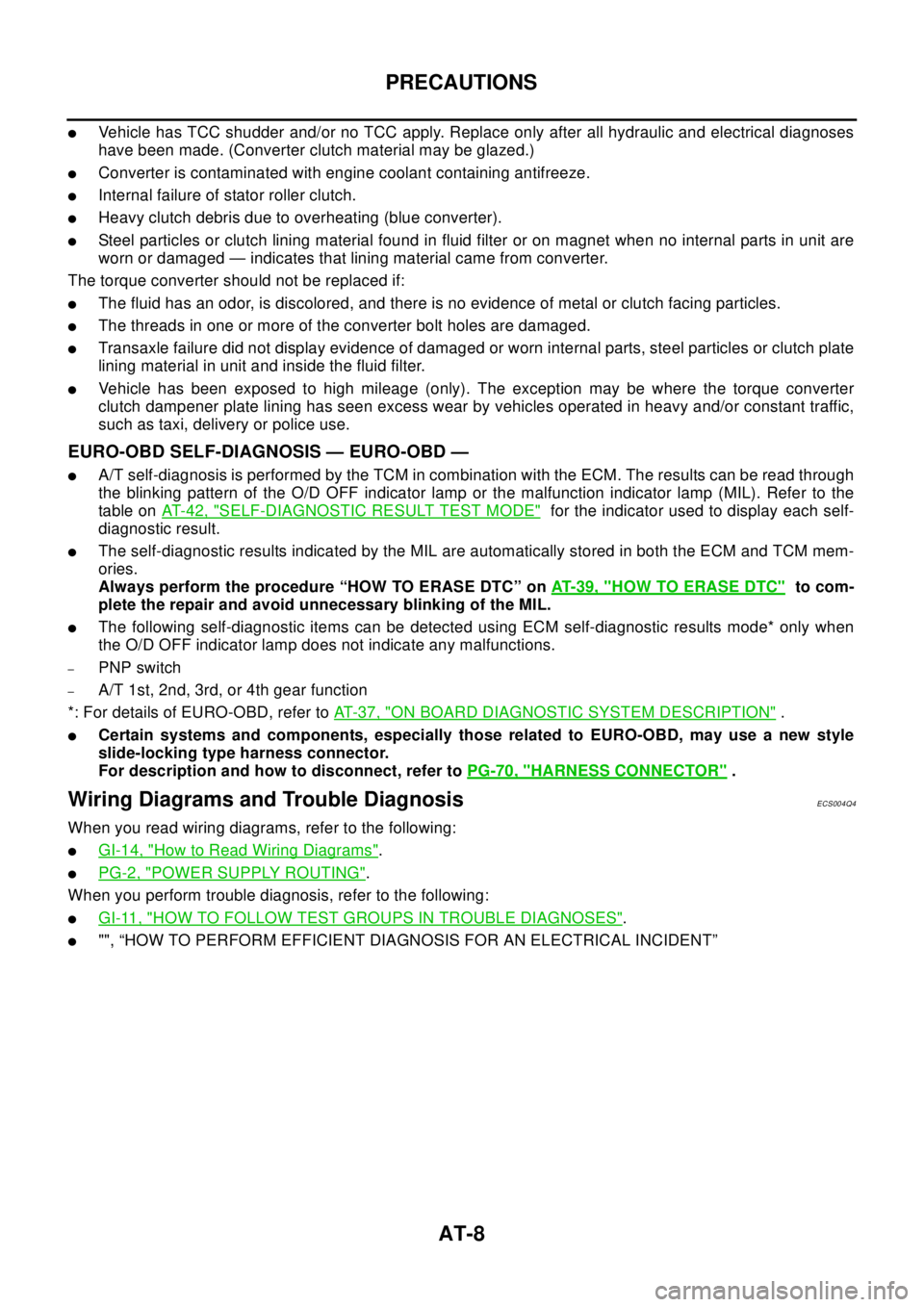
lVehicle has TCC shudder and/or no TCC apply. Replace only after all hydraulic and electrical diagnoses
have been made. (Converter clutch material may be glazed.)
lConverter is contaminated with engine coolant containing antifreeze.
lInternal failure of stator roller clutch.
lHeavy clutch debris due to overheating (blue converter).
lSteel particles or clutch lining material found in fluid filter or on magnet when no internal parts in unit are
worn or damaged — indicates that lining material came from converter.
The torque converter should not be replaced if:
lThe fluid has an odor, is discolored, and there is no evidence of metal or clutch facing particles.
lThe threads in one or more of the converter bolt holes are damaged.
lTransaxle failure did not display evidence of damaged or worn internal parts, steel particles or clutch plate
lining material in unit and inside the fluid filter.
lVehicle has been exposed to high mileage (only). The exception may be where the torque converter
clutch dampener plate lining has seen excess wear by vehicles operated in heavy and/or constant traffic,
such as taxi, delivery or police use.
EURO-OBD SELF-DIAGNOSIS — EURO-OBD —
lA/T self-diagnosis is performed by the TCM in combination with the ECM. The results can be read through
the blinking pattern of the O/D OFF indicator lamp or the malfunction indicator lamp (MIL). Refer to the
table onAT-42, "
SELF-DIAGNOSTIC RESULT TEST MODE"for the indicator used to display each self-
diagnostic result.
lThe self-diagnostic results indicated by the MIL are automatically stored in both the ECM and TCM mem-
ories.
Always perform the procedure “HOW TO ERASE DTC” onAT-39, "
HOW TO ERASE DTC"to com-
plete the repair and avoid unnecessary blinking of the MIL.
lThe following self-diagnostic items can be detected using ECM self-diagnostic results mode* only when
the O/D OFF indicator lamp does not indicate any malfunctions.
–PNP switch
–A/T 1st, 2nd, 3rd, or 4th gear function
*: For details of EURO-OBD, refer toAT - 3 7 , "
ON BOARD DIAGNOSTIC SYSTEM DESCRIPTION".
lCertain systems and components, especially those related to EURO-OBD, may use a new style
slide-locking type harness connector.
For description and how to disconnect, refer toPG-70, "
HARNESS CONNECTOR".
Wiring Diagrams and Trouble DiagnosisECS004Q4
When you read wiring diagrams, refer to the following:
lGI-14, "How to Read Wiring Diagrams".
lPG-2, "POWER SUPPLY ROUTING".
When you perform trouble diagnosis, refer to the following:
lGI-11, "HOW TO FOLLOW TEST GROUPS IN TROUBLE DIAGNOSES".
l"", “HOW TO PERFORM EFFICIENT DIAGNOSIS FOR AN ELECTRICAL INCIDENT”
Page 70 of 3066
![NISSAN X-TRAIL 2003 Electronic Repair Manual AT-64
[EURO-OBD]
TROUBLE DIAGNOSIS — BASIC INSPECTION
TROUBLE DIAGNOSIS — BASIC INSPECTION
PFP:00000
A/T Fluid CheckECS0 04 QQ
FLUID LEAKAGE CHECK
1. Clean area suspected of leaking. — for examp NISSAN X-TRAIL 2003 Electronic Repair Manual AT-64
[EURO-OBD]
TROUBLE DIAGNOSIS — BASIC INSPECTION
TROUBLE DIAGNOSIS — BASIC INSPECTION
PFP:00000
A/T Fluid CheckECS0 04 QQ
FLUID LEAKAGE CHECK
1. Clean area suspected of leaking. — for examp](/manual-img/5/57402/w960_57402-69.png)
AT-64
[EURO-OBD]
TROUBLE DIAGNOSIS — BASIC INSPECTION
TROUBLE DIAGNOSIS — BASIC INSPECTION
PFP:00000
A/T Fluid CheckECS0 04 QQ
FLUID LEAKAGE CHECK
1. Clean area suspected of leaking. — for example, mating surface
of converter housing and transmission case.
2. Start engine, apply foot brake, place selector lever in “D” posi-
tion and wait a few minutes.
3. Stop engine.
4. Check for fresh leakage.
FLUID CONDITION CHECK
FLUID LEVEL CHECK
Refer to “Checking A/T Fluid”,AT-13, "A/T FLUID".
SAT767B
SAT288G
Fluid color Suspected problem
Dark or black with burned odor Wear of frictional material
Milky pink Water contamination — Road water
entering through filler tube or breather
Varnished fluid, light to dark brown and
tackyOxidation — Over or under filling, —
Overheating
SAT638A
Page 123 of 3066
![NISSAN X-TRAIL 2003 Electronic Repair Manual TROUBLE DIAGNOSIS — GENERAL DESCRIPTION
AT-117
[EURO-OBD]
D
E
F
G
H
I
J
K
L
MA
B
ATLarge shock changing from “12”to
“1
1” in “1” position.ON vehicle 1. Control valve assemblyAT-454,
"Con NISSAN X-TRAIL 2003 Electronic Repair Manual TROUBLE DIAGNOSIS — GENERAL DESCRIPTION
AT-117
[EURO-OBD]
D
E
F
G
H
I
J
K
L
MA
B
ATLarge shock changing from “12”to
“1
1” in “1” position.ON vehicle 1. Control valve assemblyAT-454,
"Con](/manual-img/5/57402/w960_57402-122.png)
TROUBLE DIAGNOSIS — GENERAL DESCRIPTION
AT-117
[EURO-OBD]
D
E
F
G
H
I
J
K
L
MA
B
ATLarge shock changing from “12”to
“1
1” in “1” position.ON vehicle 1. Control valve assemblyAT-454,
"Control
Va lv e
Assembly
and Accu-
mulators"
¬
OFF vehicle 2. Low & reverse brakeAT-518,
"Low&
Reverse
Brake"
¬
Transmission overheats. ON vehicle1. Fluid levelAT-64,
"FLUID
LEVEL
CHECK"
¬
2. Engine idling rpm"EC-XX",
“Idle Speed
and Ignition
Timin g”¬
3. Throttle position sensor (Accelerator
pedal position (App) sensor) AdjustmentEC-154, "
DTC P0121 APP
SENSOR"
4. Line pressure testAT-68, "
Line
Pressure
Te s t"
¬
5. Line pressure solenoid valveAT-436,
"LINE
PRES-
SURE
SOLENOID
VA LV E"
AT-186,
"DTC P0745
LINE PRES-
SURE
SOLENOID
VA LV E"
6. Control valve assemblyAT-454,
"Control
Va lv e
Assembly
and Accu-
mulators"
¬ Symptom Condition Diagnostic ItemReference Page
Except for
Euro-OBDEURO-OBD
Page 292 of 3066
![NISSAN X-TRAIL 2003 Electronic Repair Manual AT-286
[EXC.F/EURO-OBD]
TROUBLE DIAGNOSIS — BASIC INSPECTION
TROUBLE DIAGNOSIS — BASIC INSPECTION
PFP:00000
A/T Fluid CheckECS004VR
FLUID LEAKAGE CHECK
1. Clean area suspected of leaking. — for NISSAN X-TRAIL 2003 Electronic Repair Manual AT-286
[EXC.F/EURO-OBD]
TROUBLE DIAGNOSIS — BASIC INSPECTION
TROUBLE DIAGNOSIS — BASIC INSPECTION
PFP:00000
A/T Fluid CheckECS004VR
FLUID LEAKAGE CHECK
1. Clean area suspected of leaking. — for](/manual-img/5/57402/w960_57402-291.png)
AT-286
[EXC.F/EURO-OBD]
TROUBLE DIAGNOSIS — BASIC INSPECTION
TROUBLE DIAGNOSIS — BASIC INSPECTION
PFP:00000
A/T Fluid CheckECS004VR
FLUID LEAKAGE CHECK
1. Clean area suspected of leaking. — for example, mating surface
of converter housing and transmission case.
2. Start engine, apply foot brake, place selector lever in “D” posi-
tion and wait a few minutes.
3. Stop engine.
4. Check for fresh leakage.
FLUID CONDITION CHECK
FLUID LEVEL CHECK
Refer to “Checking A/T Fluid”,AT-13, "A/T FLUID".
SAT767B
SAT288G
Fluid color Suspected problem
Dark or black with burned odor Wear of frictional material
Milky pink Water contamination — Road water
entering through filler tube or breather
Varnished fluid, light to dark brown and
tackyOxidation — Over or under filling, —
Overheating
SAT638A
Page 345 of 3066
![NISSAN X-TRAIL 2003 Electronic Repair Manual TROUBLE DIAGNOSIS — GENERAL DESCRIPTION
AT-339
[EXC.F/EURO-OBD]
D
E
F
G
H
I
J
K
L
MA
B
ATLarge shock changing from “12”to
“1
1” in “1” position.ON vehicle 1. Control valve assemblyAT-454 NISSAN X-TRAIL 2003 Electronic Repair Manual TROUBLE DIAGNOSIS — GENERAL DESCRIPTION
AT-339
[EXC.F/EURO-OBD]
D
E
F
G
H
I
J
K
L
MA
B
ATLarge shock changing from “12”to
“1
1” in “1” position.ON vehicle 1. Control valve assemblyAT-454](/manual-img/5/57402/w960_57402-344.png)
TROUBLE DIAGNOSIS — GENERAL DESCRIPTION
AT-339
[EXC.F/EURO-OBD]
D
E
F
G
H
I
J
K
L
MA
B
ATLarge shock changing from “12”to
“1
1” in “1” position.ON vehicle 1. Control valve assemblyAT-454,
"Control
Va lv e
Assembly
and Accu-
mulators"
¬
OFF vehicle 2. Low & reverse brakeAT-518,
"Low&
Reverse
Brake"
¬
Transmission overheats. ON vehicle1. Fluid levelAT-286,
"FLUID
LEVEL
CHECK"
¬
2. Engine idling rpm"EC-XX",
“Idle Speed
and Ignition
Timin g”¬
3. Throttle position sensor (Accelerator
pedal position (App) sensor) AdjustmentEC-154, "
DTC P0121 APP
SENSOR"
4. Line pressure testAT-290,"Line Pres-
sure Test"
¬
5. Line pressure solenoid valveAT-436,
"LINE
PRES-
SURE
SOLENOID
VA LV E"
AT-186,
"DTC P0745
LINE PRES-
SURE
SOLENOID
VA LV E"
6. Control valve assemblyAT-454,
"Control
Va lv e
Assembly
and Accu-
mulators"
¬ Symptom Condition Diagnostic ItemReference Page
Except for
Euro-OBDEURO-OBD
Page 664 of 3066

ATC-86
TROUBLE DIAGNOSIS
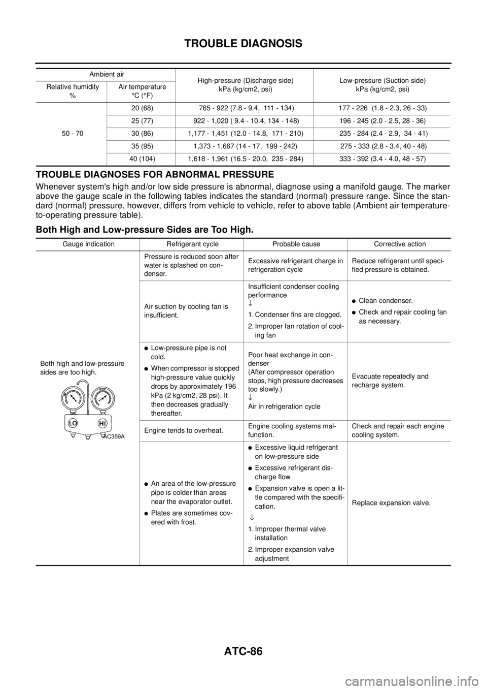
TROUBLE DIAGNOSES FOR ABNORMAL PRESSURE
Whenever system's high and/or low side pressure is abnormal, diagnose using a manifold gauge. The marker
above the gauge scale in the following tables indicates the standard (normal) pressure range. Since the stan-
dard (normal) pressure, however, differs from vehicle to vehicle, refer to above table (Ambient air temperature-
to-operating pressure table).
Both High and Low-pressure Sides are Too High.
Ambient air
High-pressure (Discharge side)
kPa (kg/cm2, psi)Low-pressure (Suction side)
kPa (kg/cm2, psi) Relative humidity
%Air temperature
°C(°F)
50 - 7020 (68) 765 - 922 (7.8 - 9.4, 111 - 134) 177 - 226 (1.8 - 2.3, 26 - 33)
25 (77) 922 - 1,020 ( 9.4 - 10.4, 134 - 148) 196 - 245 (2.0 - 2.5, 28 - 36)
30 (86) 1,177 - 1,451 (12.0 - 14.8, 171 - 210) 235 - 284 (2.4 - 2.9, 34 - 41)
35 (95) 1,373 - 1,667 (14 - 17, 199 - 242) 275 - 333 (2.8 - 3.4, 40 - 48)
40 (104) 1,618 - 1,961 (16.5 - 20.0, 235 - 284) 333 - 392 (3.4 - 4.0, 48 - 57)
Gauge indication Refrigerant cycle Probable cause Corrective action
Both high and low-pressure
sides are too high.Pressure is reduced soon after
water is splashed on con-
denser.Excessive refrigerant charge in
refrigeration cycleReduce refrigerant until speci-
fied pressure is obtained.
Air suction by cooling fan is
insufficient.Insufficient condenser cooling
performance
¯
1. Condenser fins are clogged.
2. Improper fan rotation of cool-
ing fan
lClean condenser.
lCheck and repair cooling fan
as necessary.
lLow-pressure pipe is not
cold.
lWhen compressor is stopped
high-pressure value quickly
drops by approximately 196
kPa (2 kg/cm2, 28 psi). It
then decreases gradually
thereafter.Poor heat exchange in con-
denser
(After compressor operation
stops, high pressure decreases
too slowly.)
¯
Air in refrigeration cycleEvacuate repeatedly and
recharge system.
Engine tends to overheat.Engine cooling systems mal-
function.Check and repair each engine
cooling system.
lAn area of the low-pressure
pipe is colder than areas
near the evaporator outlet.
lPlates are sometimes cov-
ered with frost.
lExcessive liquid refrigerant
on low-pressure side
lExcessive refrigerant dis-
charge flow
lExpansion valve is open a lit-
tle compared with the specifi-
cation.
¯
1. Improper thermal valve
installation
2. Improper expansion valve
adjustmentReplace expansion valve.
AC359A
Page 1011 of 3066

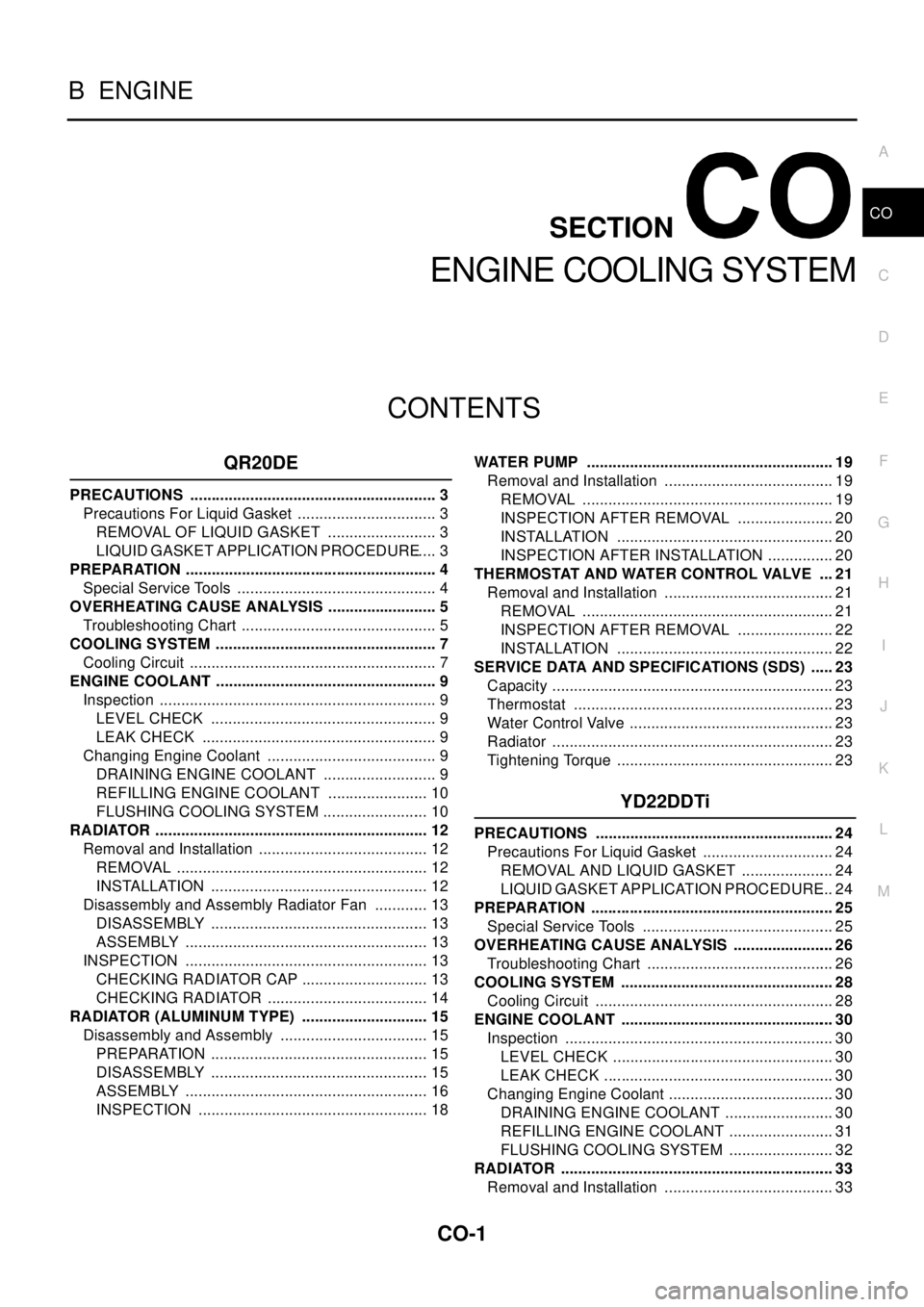
CO-1
ENGINE COOLING SYSTEM
B ENGINE
CONTENTS
C
D
E
F
G
H
I
J
K
L
M
SECTION
A
CO
ENGINE COOLING SYSTEM
QR20DE
PRECAUTIONS .......................................................... 3
Precautions For Liquid Gasket ................................. 3
REMOVAL OF LIQUID GASKET .......................... 3
LIQUID GASKET APPLICATION PROCEDURE..... 3
PREPARATION ........................................................... 4
Special Service Tools ............................................... 4
OVERHEATING CAUSE ANALYSIS .......................... 5
Troubleshooting Chart .............................................. 5
COOLING SYSTEM .................................................... 7
Cooling Circuit .......................................................... 7
ENGINE COOLANT .................................................... 9
Inspection ................................................................. 9
LEVEL CHECK ..................................................... 9
LEAK CHECK ....................................................... 9
Changing Engine Coolant ........................................ 9
DRAINING ENGINE COOLANT ........................... 9
REFILLING ENGINE COOLANT ........................ 10
FLUSHING COOLING SYSTEM ......................... 10
RADIATOR ................................................................ 12
Removal and Installation ........................................ 12
REMOVAL ........................................................... 12
INSTALLATION ................................................... 12
Disassembly and Assembly Radiator Fan ............. 13
DISASSEMBLY ................................................... 13
ASSEMBLY ......................................................... 13
INSPECTION ......................................................... 13
CHECKING RADIATOR CAP .............................. 13
CHECKING RADIATOR ...................................... 14
RADIATOR (ALUMINUM TYPE) .............................. 15
Disassembly and Assembly ................................... 15
PREPARATION ................................................... 15
DISASSEMBLY ................................................... 15
ASSEMBLY ......................................................... 16
INSPECTION ...................................................... 18WATER PUMP .......................................................... 19
Removal and Installation ........................................ 19
REMOVAL ........................................................... 19
INSPECTION AFTER REMOVAL ....................... 20
INSTALLATION ................................................... 20
INSPECTION AFTER INSTALLATION ................ 20
THERMOSTAT AND WATER CONTROL VALVE .... 21
Removal and Installation ........................................ 21
REMOVAL ........................................................... 21
INSPECTION AFTER REMOVAL ....................... 22
INSTALLATION ................................................... 22
SERVICE DATA AND SPECIFICATIONS (SDS) ...... 23
Capacity .................................................................. 23
Thermostat ............................................................. 23
Water Control Valve ................................................ 23
Radiator .................................................................. 23
Tightening Torque ................................................... 23
YD22DDTi
PRECAUTIONS ........................................................ 24
Precautions For Liquid Gasket ............................... 24
REMOVAL AND LIQUID GASKET ...................... 24
LIQUID GASKET APPLICATION PROCEDURE... 24
PREPARATION ......................................................... 25
Special Service Tools ............................................. 25
OVERHEATING CAUSE ANALYSIS ........................ 26
Troubleshooting Chart ............................................ 26
COOLING SYSTEM .................................................. 28
Cooling Circuit ........................................................ 28
ENGINE COOLANT .................................................. 30
Inspection ............................................................... 30
LEVEL CHECK .................................................... 30
LEAK CHECK ...................................................... 30
Changing Engine Coolant ....................................... 30
DRAINING ENGINE COOLANT .......................... 30
REFILLING ENGINE COOLANT ......................... 31
FLUSHING COOLING SYSTEM ......................... 32
RADIATOR ................................................................ 33
Removal and Installation ........................................ 33
Page 1016 of 3066
![NISSAN X-TRAIL 2003 Electronic Repair Manual CO-6
[QR20DE]
OVERHEATING CAUSE ANALYSIS
Except cool-
ing system
parts mal-
function— OverloadonengineAbusive drivingHigh engine rpm under no
load
Driving in low gear for
extended time
Driving at ex NISSAN X-TRAIL 2003 Electronic Repair Manual CO-6
[QR20DE]
OVERHEATING CAUSE ANALYSIS
Except cool-
ing system
parts mal-
function— OverloadonengineAbusive drivingHigh engine rpm under no
load
Driving in low gear for
extended time
Driving at ex](/manual-img/5/57402/w960_57402-1015.png)
CO-6
[QR20DE]
OVERHEATING CAUSE ANALYSIS
Except cool-
ing system
parts mal-
function— OverloadonengineAbusive drivingHigh engine rpm under no
load
Driving in low gear for
extended time
Driving at extremely high
speed
Powertrain system mal-
function
— Installed improper size
wheels and tires
Dragging brakes
Improper ignition timing
Blocked or restricted air
flowBlocked bumper —
— Blocked radiator grilleInstalled car brassiere
Mud contamination or
paper clogging
Blocked radiator —
Blocked condenser
—
Installed large fog lamp Symptom Check items