2003 NISSAN X-TRAIL engine overheat
[x] Cancel search: engine overheatPage 1885 of 3066
![NISSAN X-TRAIL 2003 Electronic Repair Manual DTC P1217 OVERHEAT (COOLING SYSTEM)
EC-771
[YD]
C
D
E
F
G
H
I
J
K
L
MA
EC
*1: Turn the ignition switch ON.
*2: Engine running at 3,000 rpm for 10 minutes.
*3: Drive at 90 km/h (55 MPH) for 30 minutes NISSAN X-TRAIL 2003 Electronic Repair Manual DTC P1217 OVERHEAT (COOLING SYSTEM)
EC-771
[YD]
C
D
E
F
G
H
I
J
K
L
MA
EC
*1: Turn the ignition switch ON.
*2: Engine running at 3,000 rpm for 10 minutes.
*3: Drive at 90 km/h (55 MPH) for 30 minutes](/manual-img/5/57402/w960_57402-1884.png)
DTC P1217 OVERHEAT (COOLING SYSTEM)
EC-771
[YD]
C
D
E
F
G
H
I
J
K
L
MA
EC
*1: Turn the ignition switch ON.
*2: Engine running at 3,000 rpm for 10 minutes.
*3: Drive at 90 km/h (55 MPH) for 30 minutes and then let idle for 10 minutes.
*4: After 60 minutes of cool down time.
For more information, refer toCO-26, "
OVERHEATING CAUSE ANALYSIS".
Component InspectionEBS004QZ
COOLING FAN RELAY-1, -2 AND -3
Check continuity between terminals 3 and 5, 6 and 7 under the fol-
lowing conditions.
COOLING FAN MOTOR-1 AND -2
Supply battery voltage between the following terminals and check
operation.
ON*39lCoolant temperature
gaugelVisual Gauge less than 3/4
when driving—
lCoolant overflow to
reservoir tanklVisual No overflow during driv-
ing and idlingSeeMA-27, "Changing
Engine Coolant".
OFF*
410lCoolant return from
reservoir tank to radia-
torlVisual Should be initial level in
reservoir tankSeeMA-28, "REFILLING
ENGINE COOLANT".
OFF 11
lCylinder headlStraight gauge feeler
gauge0.1mm (0.004 in) Maxi-
mum distortion (warping)SeeEM-173, "CYLIN-
DER HEAD".
12
lCylinder block and pis-
tonslVisual No scuffing on cylinder
walls or pistonSeeEM-188, "CYLIN-
DER BLOCK". Engine Step Inspection item Equipment Condition Reference page
Conditions Continuity
12V direct current supply between ter-
minals 1 and 2Ye s
No current supply No
SEF745U
SpeedTe r m i n a l s
(+) (–)
Cooling fan motor-1Low 1 4
High 1, 2 3, 4
Cooling fan motor-2Low 1 4
High 1, 2 3, 4
PBIB0423E
Page 2363 of 3066

IDX-6
ALPHABETICAL INDEX
Intake manifold(YD22DDTi) ............................EM-115
Intake sensor ................................ATC-101,ATC-108
Intake valve timing control .................EC-117,EC-608
Intake valve timing control solenoid valve ......EC-266,
EC-608
Interior .......................EI-23,EI-25,EI-26,EI-28,EI-29
Interior lamp ........................................................LT-55
Interior lamp on-off control ......................LT-55,LT-56
ISO 15031-5 Mode 1 - 9 ....................................EC-36
IVC - Wiring diagram .......................................EC-268
IVC/V - Wiring diagram ....................................EC-610
J
Joint connector (J/C) .............................PG-72
,PG-76
K
Keyless entry system - See Multi-remote control system
BL-45
Knock sensor (KS) .............................EC-212,EC-496
KS - Wiring diagram ...........................EC-214,EC-498
L
LAN system circuit ...........................................ATC-56
License lamp .......................................................LT-30
Line pressure solenoid valve ...........................AT-179
Line pressure test (A/T) .......................AT-68,AT-290
Liquid gasket application(QR20DE) ....................EM-6
Liquid gasket application(YD22DDTi) .............EM-103
LOAD - Wiring diagram ......................EC-363,EC-638
Location of electrical units .................................PG-64
Lock, door ...............................................BL-54,BL-57
Lubricant (R134a) A/C ........................ATC-5,ATC-21
Lubricants .........................................................MA-17
Lubrication circuit (engine)(QR20DE) ..................LU-5
Lubrication circuit (engine)(YD22DDTi) .............LU-17
Lubrication-locks, hinges and hood latches ......MA-42
M
M/T major overhaul ...............................MT-27
,MT-35
M/T oil replacement ...........................................MT-11
M/T removal and installation ..............................MT-16
MAFS - Wiring diagram .....EC-132,EC-262,EC-466,
EC-708
Magnet clutch .................................ATC-73,ATC-129
MAIN - Wiring diagram .......EC-108,EC-454,EC-701
Mainshaft (M/T) .....................................MT-19,MT-24
Major overhaul (Transfer) ..................................TF-14
Malfunction indicator (MI) ...EC-252,EC-526,EC-667
Malfunction indicator lamp (MIL) ..........EC-48,EC-404
Mass air flow sensor (MAFS) ............EC-130,EC-260,
EC-463
,EC-706
Master cylinder (brake) ......................................BR-13
Master cylinder (clutch) ........................................CL-9
METER - Wiring diagram ...........................DI-8,DI-26
MIL - Wiring diagram ........................EC-253,EC-527
MIL/DL - Wiring diagram ..................................EC-825
MIRROR - Wiring diagram ...............................GW-47
Mirror defogger ................................................GW-10
Mirror, door ......................................................GW-46
Mirror, out side .................................................GW-46
Misfire ..............................................................EC-206
Mode door control linkage adjustment ...........ATC-61,
ATC-118
,MTC-8,MTC-27
Mode door motor ............................ATC-58,ATC-118
Molding - See Exterior ........GW-3,EI-14,EI-16,EI-17
Mud guard - See Exterior ....................................EI-16
MULTI - Wiring diagram .....................................BL-47
Multiport fuel injection (MFI) system ...EC-24,EC-389
Multi-remote control system ...............................BL-45
N
NATS - Wiring diagram ......................................BL-72
NATS (Nissan anti-theft system) .......................BL-70
NVH troubleshooting (BR) .........................BR-5,PB-2
NVH troubleshooting (CL) ....................................CL-4
NVH troubleshooting (EM)(QR20DE) ...............EM-11
NVH troubleshooting (EM)(YD22DDTi) ..........EM-108
NVH troubleshooting (FSU) ..............................FSU-4
NVH troubleshooting (M/T) .................................MT-8
NVH troubleshooting (PR) .................................FAX-6
NVH troubleshooting (RA) ................................RAX-5
NVH troubleshooting (RAX) ..............................RAX-5
NVH troubleshooting (RSU) ..............................RSU-4
NVH troubleshooting (ST) ....................................PS-4
NVH troubleshooting (Transfer) ...........................TF-7
NVH troubleshooting (WT) ..................................WT-2
O
Oil cooler (engine)(QR20DE) .............................LU-13
Oil cooler (engine)(YD22DDTi) ..........................LU-25
Oil filter(QR20DE) ................................................LU-9
Oil filter(YD22DDTi) ...........................................LU-20
Oil pan (engine)(QR20DE) ...............................EM-24
Oil pan (engine)(YD22DDTi) ...........................EM-125
Oil pressure (engine)(QR20DE) ..........................LU-7
Oil pressure (engine)(YD22DDTi) ......................LU-18
Oil pump (engine)(QR20DE) .............................LU-10
Oil pump (engine)(YD22DDTi) ...........................LU-23
Oil pump regulator valve (engine)(QR20DE) .....LU-11
Oil pump regulator valve (engine)(YD22DDTi) ..LU-24
On board diagnostic system ...............EC-36,EC-401
Operating cylinder (clutch) .................................CL-11
Out side mirror .................................................GW-46
Overdrive control switch ....................AT-265,AT-387
Overheat ..........................................................EC-761
Oversize piston(QR20DE) ................................EM-85
Oversize piston(YD22DDTi) ...........................EM-204
Page 2513 of 3066

ENGINE MAINTENANCE (QR20DE)
MA-21
C
D
E
F
G
H
I
J
K
MA
B
MA
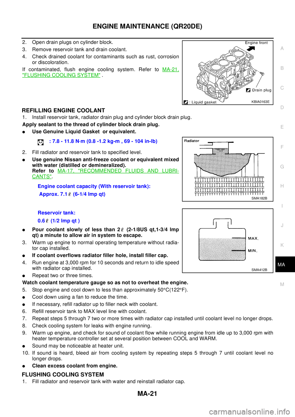
2. Open drain plugs on cylinder block.
3. Remove reservoir tank and drain coolant.
4. Check drained coolant for contaminants such as rust, corrosion
or discoloration.
If contaminated, flush engine cooling system. Refer toMA-21,
"FLUSHING COOLING SYSTEM".
REFILLING ENGINE COOLANT
1. Install reservoir tank, radiator drain plug and cylinder block drain plug.
Apply sealant to the thread of cylinder block drain plug.
lUse Genuine Liquid Gasket or equivalent.
2. Fill radiator and reservoir tank to specified level.
lUse genuine Nissan anti-freeze coolant or equivalent mixed
with water (distilled or demineralized).
Refer toMA-17, "
RECOMMENDED FLUIDS AND LUBRI-
CANTS".
lPour coolant slowly of less than 2 (2-1/8US qt,1-3/4 lmp
qt) a minute to allow air in system to escape.
3. Warm up engine to normal operating temperature without radia-
tor cap installed.
lIf coolant overflows radiator filler hole, install filler cap.
4. Run engine at 3,000 rpm for 10 seconds and return to idle speed
with radiator cap installed.
lRepeat two or three times.
Watch coolant temperature gauge so as not to overheat the engine.
5. Stop engine and cool down to less than approximately 50°C(122°F).
lCool down using a fan to reduce the time.
lIf necessary, refill radiator up to filler neck with coolant.
6. Refill reservoir tank to MAX level line with coolant.
7. Repeat steps 5 through 7 two or more times with radiator cap installed until coolant level no longer drops.
8. Check cooling system for leaks with engine running.
9. Warm up engine, and check for sound of coolant flow while running engine from idle up to 3,000 rpm with
heater temperature controller set at several position between COOL and WARM.
lSound may be noticeable at heater unit.
10. If sound is heard, bleed air from cooling system by repeating steps 5 through 7 until coolant level no
longer drops.
lClean excess coolant from engine.
FLUSHING COOLING SYSTEM
1. Fill radiator and reservoir tank with water and reinstall radiator cap.
KBIA0163E
: 7.8 - 11.8 N·m (0.8 -1.2 kg-m , 69 - 104 in-lb)
Engine coolant capacity (With reservoir tank):
Approx. 7.1 (6-1/4 Imp qt)
SMA182B
Reservoir tank:
0.6 (1/2 lmp qt )
SMA412B
Page 2520 of 3066

MA-28
ENGINE MAINTENANCE (YD22DDTI)
REFILLING ENGINE COOLANT
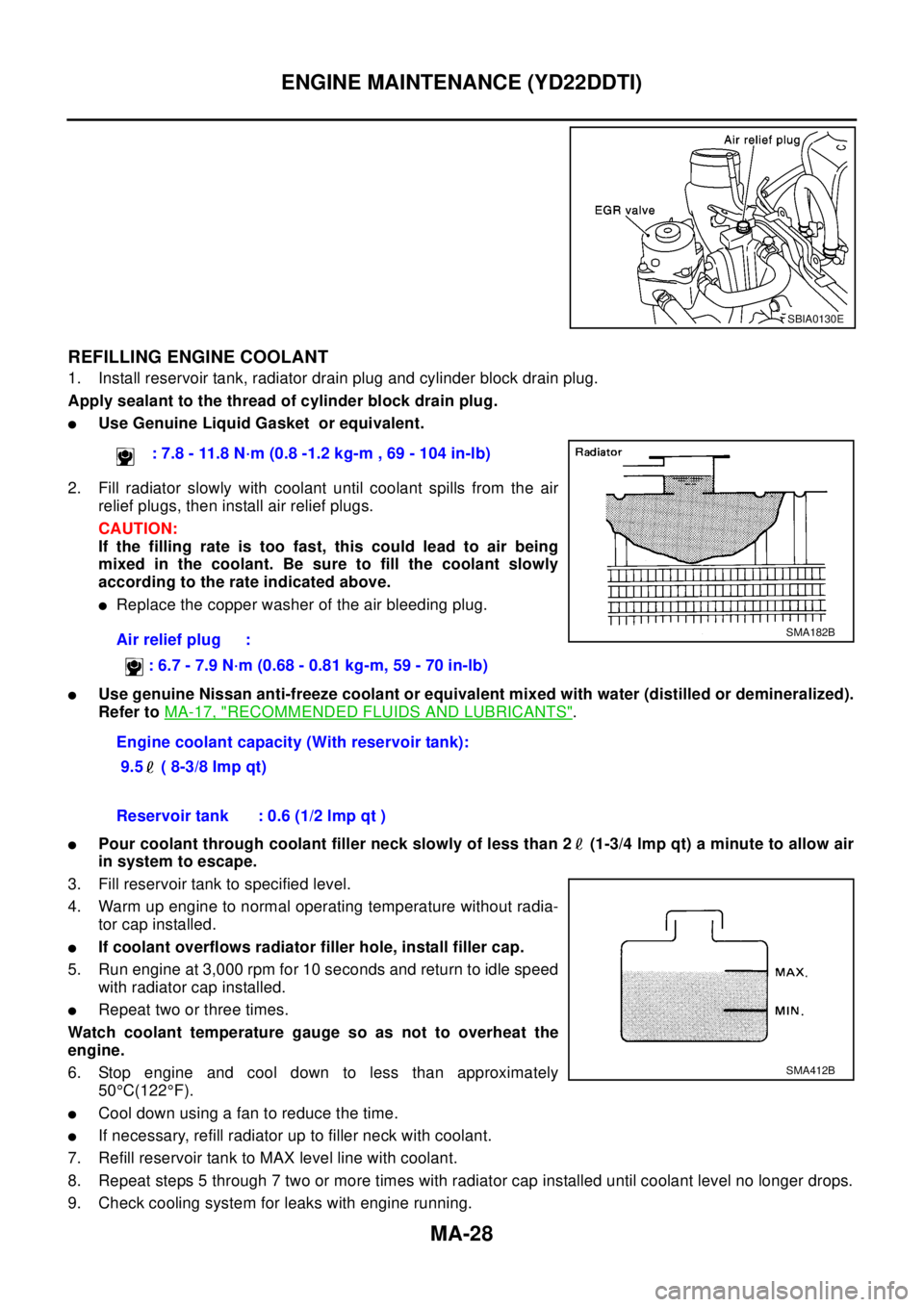
1. Install reservoir tank, radiator drain plug and cylinder block drain plug.
Apply sealant to the thread of cylinder block drain plug.
lUse Genuine Liquid Gasket or equivalent.
2. Fill radiator slowly with coolant until coolant spills from the air
relief plugs, then install air relief plugs.
CAUTION:
If the filling rate is too fast, this could lead to air being
mixed in the coolant. Be sure to fill the coolant slowly
according to the rate indicated above.
lReplace the copper washer of the air bleeding plug.
lUse genuine Nissan anti-freeze coolant or equivalent mixed with water (distilled or demineralized).
Refer toMA-17, "
RECOMMENDED FLUIDS AND LUBRICANTS".
lPour coolant through coolant filler neck slowly of less than 2 (1-3/4 lmp qt) a minute to allow air
in system to escape.
3. Fill reservoir tank to specified level.
4. Warm up engine to normal operating temperature without radia-
tor cap installed.
lIf coolant overflows radiator filler hole, install filler cap.
5. Run engine at 3,000 rpm for 10 seconds and return to idle speed
with radiator cap installed.
lRepeat two or three times.
Watch coolant temperature gauge so as not to overheat the
engine.
6. Stop engine and cool down to less than approximately
50°C(122°F).
lCool down using a fan to reduce the time.
lIf necessary, refill radiator up to filler neck with coolant.
7. Refill reservoir tank to MAX level line with coolant.
8. Repeat steps 5 through 7 two or more times with radiator cap installed until coolant level no longer drops.
9. Check cooling system for leaks with engine running.
SBIA0130E
: 7.8 - 11.8 N·m (0.8 -1.2 kg-m , 69 - 104 in-lb)
Air relief plug :
:6.7-7.9N·m(0.68-0.81kg-m,59-70in-lb)
Engine coolant capacity (With reservoir tank):
9.5 ( 8-3/8 Imp qt)
SMA182B
Reservoir tank : 0.6 (1/2 lmp qt )
SMA412B