2003 NISSAN X-TRAIL engine coolant
[x] Cancel search: engine coolantPage 1052 of 3066
![NISSAN X-TRAIL 2003 Electronic Repair Manual CO-42
[YD22DDTi]
THERMOSTAT AND WATER PIPING
THERMOSTAT AND WATER PIPING
PFP:21200
Removal and InstallationEBS00BK9
WAR NIN G:
Never remove the radiator cap when the engine is hot. Serious burns could NISSAN X-TRAIL 2003 Electronic Repair Manual CO-42
[YD22DDTi]
THERMOSTAT AND WATER PIPING
THERMOSTAT AND WATER PIPING
PFP:21200
Removal and InstallationEBS00BK9
WAR NIN G:
Never remove the radiator cap when the engine is hot. Serious burns could](/manual-img/5/57402/w960_57402-1051.png)
CO-42
[YD22DDTi]
THERMOSTAT AND WATER PIPING
THERMOSTAT AND WATER PIPING
PFP:21200
Removal and InstallationEBS00BK9
WAR NIN G:
Never remove the radiator cap when the engine is hot. Serious burns could occur from high pressure
coolant escaping from the radiator.
REMOVAL
1. Remove the under cover and splash cover (right and left).
2. Drain engine coolant. Refer toCO-30, "
DRAINING ENGINE COOLANT".
CAUTION:
Perform when the engine cold.
3. Remove radiator lower hose from water inlet side.
4. Remove water inlet and thermostat.
5. Remove thermostat housing.
SBIA0133E
1 Thermostat 2 Water inlet 3 Thermostat housing
4 Water inlet pipe 5 Heater return pipe 6 Gasket
Page 1054 of 3066
![NISSAN X-TRAIL 2003 Electronic Repair Manual CO-44
[YD22DDTi]
SERVICE DATA AND SPECIFICATIONS (SDS)
SERVICE DATA AND SPECIFICATIONS (SDS)
PFP:00030
Standard and LimitEBS00CU0
CAPACITY
THERMOSTAT
RADIATOR
Unit:kPa(bar,kg/cm2,psi)
Tightening Torqu NISSAN X-TRAIL 2003 Electronic Repair Manual CO-44
[YD22DDTi]
SERVICE DATA AND SPECIFICATIONS (SDS)
SERVICE DATA AND SPECIFICATIONS (SDS)
PFP:00030
Standard and LimitEBS00CU0
CAPACITY
THERMOSTAT
RADIATOR
Unit:kPa(bar,kg/cm2,psi)
Tightening Torqu](/manual-img/5/57402/w960_57402-1053.png)
CO-44
[YD22DDTi]
SERVICE DATA AND SPECIFICATIONS (SDS)
SERVICE DATA AND SPECIFICATIONS (SDS)
PFP:00030
Standard and LimitEBS00CU0
CAPACITY
THERMOSTAT
RADIATOR
Unit:kPa(bar,kg/cm2,psi)
Tightening TorqueEBS00BKE
Unit: N·m (kg-m, ft-lb), N·m (kg-m, in-lb)* Engine coolant capacity [With reservoir tank (MAX level)]
9.5 (8-3/8 Imp qt)
Valve opening temperature 80 - 84°C (176 - 183°F)
Valve liftMore than 10 mm/ 95°C (0.39 in/203°F)
Cap relief pressureStandard 78 - 98 (0.78 - 0.98, 0.8 - 1.0, 11 - 14)
Limit 59 (0.59, 0.6, 9)
Leakage test pressure 157 (1.57, 1.6, 23)
Radiator mounting bracket
Radiator fan assembly
Radiator fan
Radiator fan motor3.9 - 4.5 (0.39 - 0.46, 34 - 39)*
3.9 - 4.5 (0.39 - 0.46, 34 - 39)*
2.9 - 3.9 (0.30 - 0.40, 26 - 34)*
4.0 - 4.9 (0.40 - 0.50, 35 - 43)*
Water pum p
Water pump pully
Water inlet
Thermostat housing
Water inlet pipe
Hater return pipe23.0 - 30.0 (2.3 - 3.1, 17 - 22)
7.3 - 9.6 (0.74 - 0.98, 65 - 85)*
21.0 - 28.0 (2.1 - 2.9, 16 - 20)
21.0 - 28.0 (2.1 - 2.9, 16 - 20)
21.0 - 28.0 (2.1 - 2.9, 16 - 20)
21.0 - 28.0 (2.1 - 2.9, 16 - 20)
Page 1058 of 3066
DI-4
COMBINATION METERS (LHD MODELS)
COMBINATION METERS (LHD MODELS)
PFP:24810
System DescriptionEKS002Z7
UNIFIED CONTROL METER
lSpeedometer, odo/trip meter, tachometer, fuel gauge and water temperature gauge are controlled totally
by control unit built-in combination meter.
lDigital meter is adopted for odo/trip meter.*
*The record of the odo meter is kept even if the battery cable is disconnected. The record of the trip meter
is erased when the battery cable is disconnected.
lOdo/trip meter segment can be checked in diagnosis mode.
lMeter/gauge can be checked in diagnosis mode.
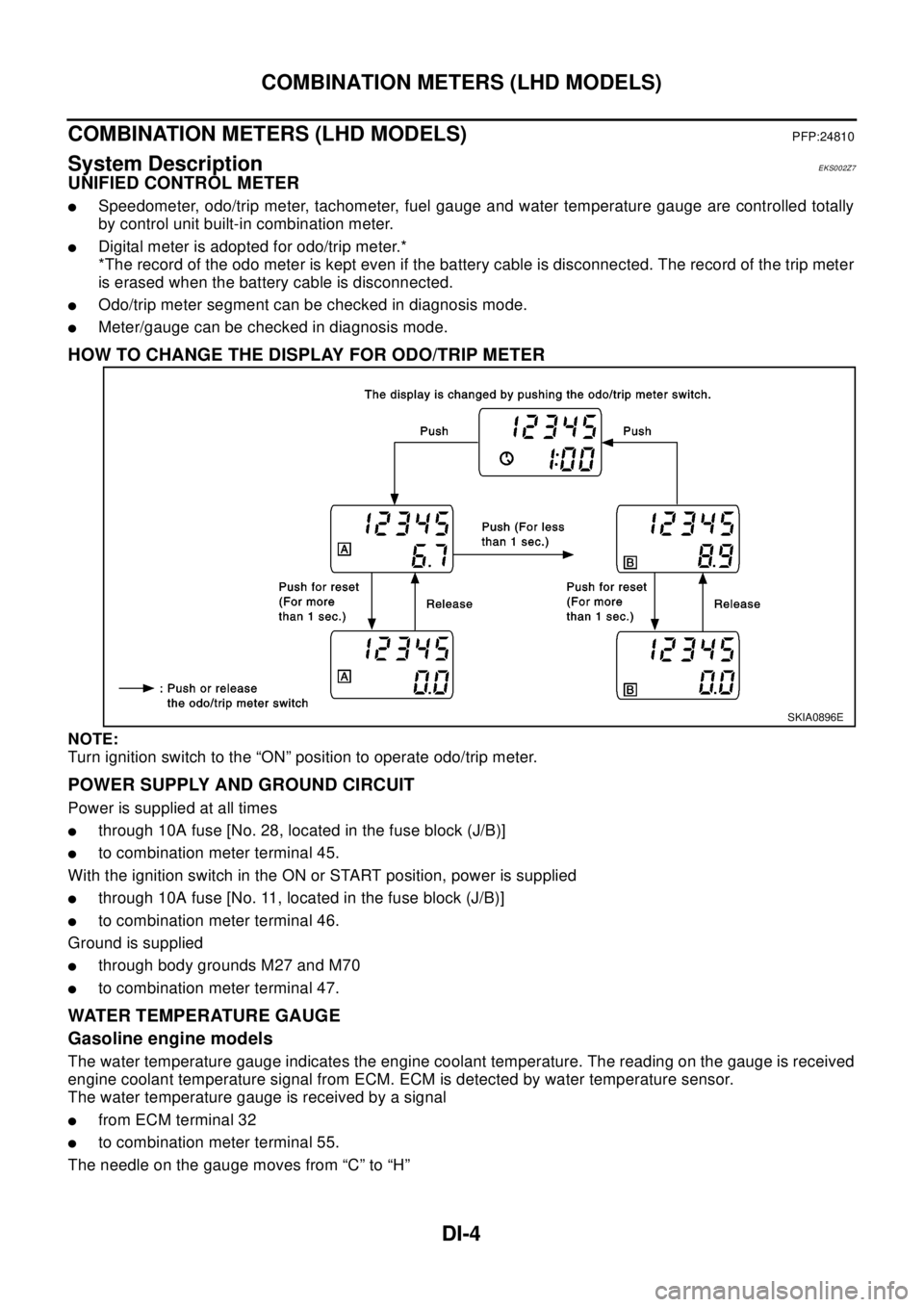
HOW TO CHANGE THE DISPLAY FOR ODO/TRIP METER
NOTE:
Turn ignition switch to the “ON” position to operate odo/trip meter.
POWER SUPPLY AND GROUND CIRCUIT
Power is supplied at all times
lthrough 10A fuse [No. 28, located in the fuse block (J/B)]
lto combination meter terminal 45.
With the ignition switch in the ON or START position, power is supplied
lthrough 10A fuse [No. 11, located in the fuse block (J/B)]
lto combination meter terminal 46.
Ground is supplied
lthrough body grounds M27 and M70
lto combination meter terminal 47.
WATER TEMPERATURE GAUGE
Gasoline engine models
The water temperature gauge indicates the engine coolant temperature. The reading on the gauge is received
engine coolant temperature signal from ECM. ECM is detected by water temperature sensor.
The water temperature gauge is received by a signal
lfrom ECM terminal 32
lto combination meter terminal 55.
The needle on the gauge moves from “C” to “H”
SKIA0896E
Page 1059 of 3066
COMBINATION METERS (LHD MODELS)
DI-5
C
D
E
F
G
H
I
J
L
MA
B
DI
Diesel engine models
The water temperature gauge indicates the engine coolant temperature. The reading on the gauge is based
on the resistance of the thermal transmitter.
As the temperature of the coolant increases, the resistance of the thermal transmitter decreases. A variable
ground is supplied to terminal 55 of the combination meter for the water temperature gauge. The needle on
the gauge moves from “C” to “H”.
TACHOMETER
The tachometer indicates engine speed in revolutions per minute (rpm).
The tachometer is regulated by a signal
lfrom terminal 36 (Gasoline engine models) or D1 (Diesel engine models) of the ECM
lto combination meter terminal 54 for the tachometer.
FUEL GAUGE
The fuel gauge indicates the approximate fuel level in the fuel tank.
The fuel gauge is regulated by a variable ground signal supplied
lfrom body grounds, B8 and B18
lthrough terminal 1 and 3 of the Sub fuel level sensor unit and
lthrough terminal 4 and 1 of the fuel level sensor unit
lto combination meter terminal 51 for the fuel gauge.
SPEEDOMETER
The combination meter provides a voltage signal to the vehicle speed signal from 4WD/ABS control unit (with-
out ESP) or 4WD control unit (with ESP).
The voltage is supplied
lfrom combination meter terminal 42 for the speedometer
lto terminal 20 of 4WD/ABS control unit (without ESP) or 4WD control unit (without ESP).
The speedometer converts the voltage into the vehicle speed displayed.
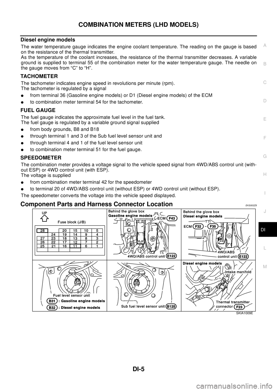
Component Parts and Harness Connector LocationEKS002Z8
SKIA1009E
Page 1076 of 3066
DI-22
COMBINATION METERS (RHD MODELS)
COMBINATION METERS (RHD MODELS)
PFP:24810
System DescriptionEKS0030H
UNIFIED CONTROL METER
lSpeedometer, odo/trip meter, tachometer, fuel gauge and water temperature gauge are controlled totally
by control unit built-in combination meter.
lDigital meter is adopted for odo/trip meter.*
*The record of the odo meter is kept even if the battery cable is disconnected. The record of the trip meter
is erased when the battery cable is disconnected.
lOdo/trip meter segment can be checked in diagnosis mode.
lMeter/gauge can be checked in diagnosis mode.
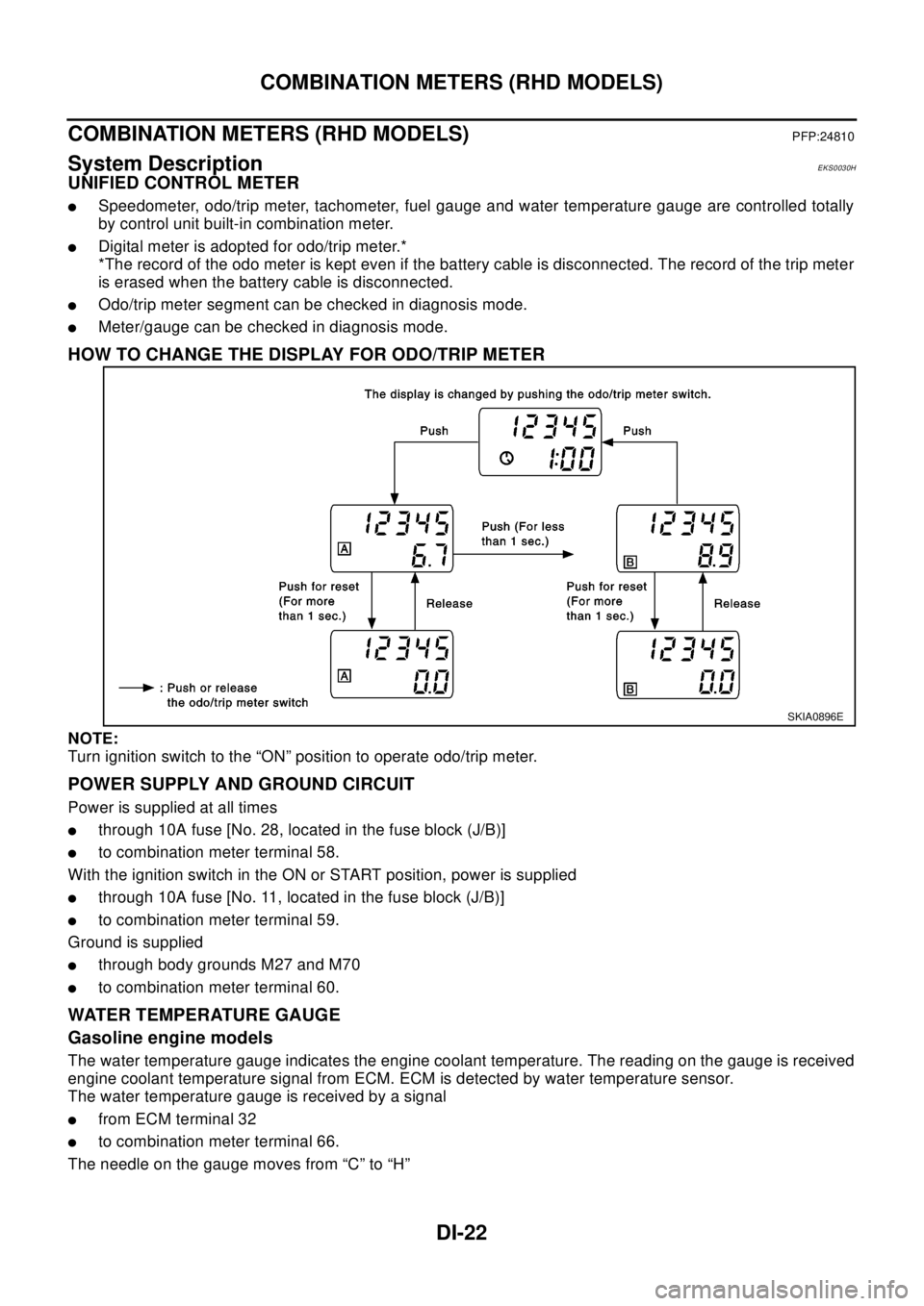
HOW TO CHANGE THE DISPLAY FOR ODO/TRIP METER
NOTE:
Turn ignition switch to the “ON” position to operate odo/trip meter.
POWER SUPPLY AND GROUND CIRCUIT
Power is supplied at all times
lthrough 10A fuse [No. 28, located in the fuse block (J/B)]
lto combination meter terminal 58.
With the ignition switch in the ON or START position, power is supplied
lthrough 10A fuse [No. 11, located in the fuse block (J/B)]
lto combination meter terminal 59.
Ground is supplied
lthrough body grounds M27 and M70
lto combination meter terminal 60.
WATER TEMPERATURE GAUGE
Gasoline engine models
The water temperature gauge indicates the engine coolant temperature. The reading on the gauge is received
engine coolant temperature signal from ECM. ECM is detected by water temperature sensor.
The water temperature gauge is received by a signal
lfrom ECM terminal 32
lto combination meter terminal 66.
The needle on the gauge moves from “C” to “H”
SKIA0896E
Page 1077 of 3066
COMBINATION METERS (RHD MODELS)
DI-23
C
D
E
F
G
H
I
J
L
MA
B
DI
Diesel engine models
The water temperature gauge indicates the engine coolant temperature. The reading on the gauge is based
on the resistance of the thermal transmitter.
As the temperature of the coolant increases, the resistance of the thermal transmitter decreases. A variable
ground is supplied to terminal 66 of the combination meter for the water temperature gauge. The needle on
the gauge moves from “C” to “H”.
TACHOMETER
The tachometer indicates engine speed in revolutions per minute (rpm).
The tachometer is regulated by a signal
lfrom terminal 36 (Gasoline engine models) or D1 (Diesel engine models) of the ECM
lto combination meter terminal 41 for the tachometer.
FUEL GAUGE
The fuel gauge indicates the approximate fuel level in the fuel tank.
The fuel gauge is regulated by a variable ground signal supplied
lfrom body grounds , B107 and B119
lthrough terminal 1 and 3 of the Sub fuel level sensor unit and
lthrough terminal 4 and 1 of the fuel level sensor unit
lto combination meter terminal 40 for the fuel gauge.
SPEEDOMETER
The combination meter provides a voltage signal to the vehicle speed signal from 4WD/ABS control unit (with-
out ESP) or 4WD control unit (with ESP).
The voltage is supplied
lfrom combination meter terminal 42 for the speedometer
lto terminal 20 of 4WD/ABS control unit (without ESP) or 4WD control unit (with ESP).
The speedometer converts the voltage into the vehicle speed displayed.
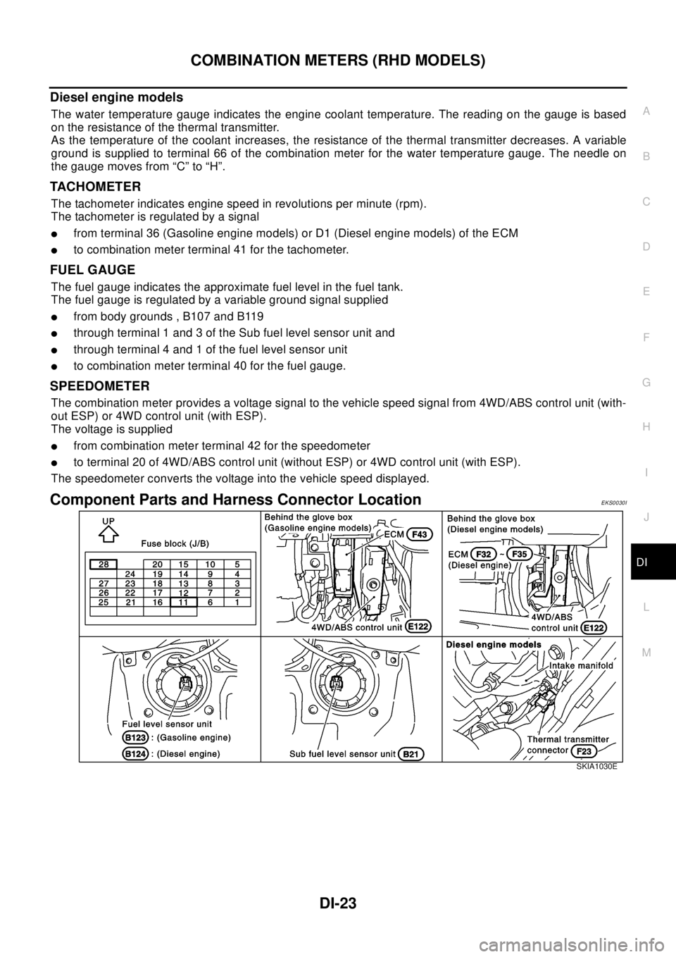
Component Parts and Harness Connector LocationEKS0030I
SKIA1030E
Page 1119 of 3066
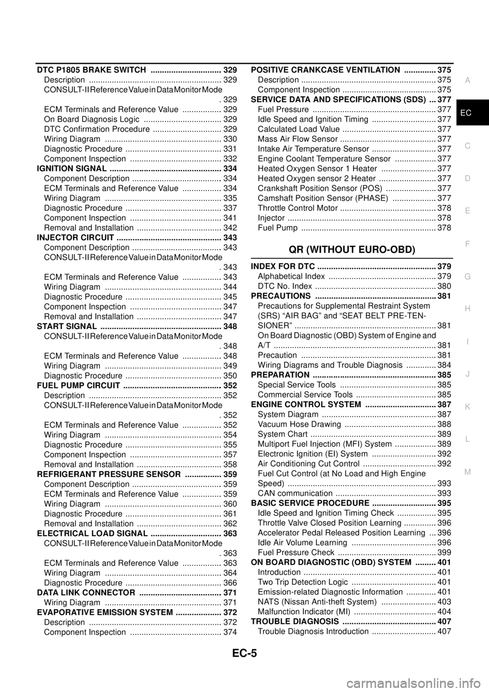
EC-5
C
D
E
F
G
H
I
J
K
L
M
ECA DTC P1805 BRAKE SWITCH ................................ 329
Description ........................................................... 329
CONSULT-II Reference Value in Data Monitor Mode
. 329
ECM Terminals and Reference Value .................. 329
On Board Diagnosis Logic ................................... 329
DTC Confirmation Procedure ............................... 329
Wiring Diagram .................................................... 330
Diagnostic Procedure ........................................... 331
Component Inspection ......................................... 332
IGNITION SIGNAL .................................................. 334
Component Description ........................................ 334
ECM Terminals and Reference Value .................. 334
Wiring Diagram .................................................... 335
Diagnostic Procedure ........................................... 337
Component Inspection ......................................... 341
Removal and Installation ...................................... 342
INJECTOR CIRCUIT ............................................... 343
Component Description ........................................ 343
CONSULT-II Reference Value in Data Monitor Mode
. 343
ECM Terminals and Reference Value .................. 343
Wiring Diagram .................................................... 344
Diagnostic Procedure ........................................... 345
Component Inspection ......................................... 347
Removal and Installation ...................................... 347
START SIGNAL ...................................................... 348
CONSULT-II Reference Value in Data Monitor Mode
. 348
ECM Terminals and Reference Value .................. 348
Wiring Diagram .................................................... 349
Diagnostic Procedure ........................................... 350
FUEL PUMP CIRCUIT ............................................ 352
Description ........................................................... 352
CONSULT-II Reference Value in Data Monitor Mode
. 352
ECM Terminals and Reference Value .................. 352
Wiring Diagram .................................................... 354
Diagnostic Procedure ........................................... 355
Component Inspection ......................................... 357
Removal and Installation ...................................... 358
REFRIGERANT PRESSURE SENSOR ................. 359
Component Description ........................................ 359
ECM Terminals and Reference Value .................. 359
Wiring Diagram .................................................... 360
Diagnostic Procedure ........................................... 361
Removal and Installation ...................................... 362
ELECTRICAL LOAD SIGNAL ................................ 363
CONSULT-II Reference Value in Data Monitor Mode
. 363
ECM Terminals and Reference Value .................. 363
Wiring Diagram .................................................... 364
Diagnostic Procedure ........................................... 366
DATA LINK CONNECTOR ..................................... 371
Wiring Diagram .................................................... 371
EVAPORATIVE EMISSION SYSTEM ..................... 372
Description ........................................................... 372
Component Inspection ......................................... 374POSITIVE CRANKCASE VENTILATION ...............375
Description ............................................................375
Component Inspection ..........................................375
SERVICE DATA AND SPECIFICATIONS (SDS) ....377
Fuel Pressure .......................................................377
Idle Speed and Ignition Timing .............................377
Calculated Load Value ..........................................377
Mass Air Flow Sensor ...........................................377
Intake Air Temperature Sensor .............................377
Engine Coolant Temperature Sensor ...................377
Heated Oxygen Sensor 1 Heater .........................377
Heated Oxygen sensor 2 Heater ..........................377
Crankshaft Position Sensor (POS) .......................377
Camshaft Position Sensor (PHASE) ....................377
Throttle Control Motor ...........................................378
Injector ..................................................................378
Fuel Pump ............................................................378
QR (WITHOUT EURO-OBD)
INDEX FOR DTC .....................................................379
Alphabetical Index ................................................379
DTC No. Index ......................................................380
PRECAUTIONS ......................................................381
Precautions for Supplemental Restraint System
(SRS) “AIR BAG” and “SEAT BELT PRE-TEN-
SIONER” ...............................................................381
On Board Diagnostic (OBD) System of Engine and
A/T ........................................................................381
Precaution ............................................................381
Wiring Diagrams and Trouble Diagnosis ..............384
PREPARATION .......................................................385
Special Service Tools ...........................................385
Commercial Service Tools ....................................385
ENGINE CONTROL SYSTEM ................................387
System Diagram ...................................................387
Vacuum Hose Drawing .........................................388
System Chart ........................................................389
Multiport Fuel Injection (MFI) System ...................389
Electronic Ignition (EI) System .............................392
Air Conditioning Cut Control .................................392
Fuel Cut Control (at No Load and High Engine
Speed) ..................................................................393
CAN communication .............................................393
BASIC SERVICE PROCEDURE .............................395
Idle Speed and Ignition Timing Check ..................395
Throttle Valve Closed Position Learning ...............396
Accelerator Pedal Released Position Learning ....396
Idle Air Volume Learning ......................................396
Fuel Pressure Check ............................................399
ON BOARD DIAGNOSTIC (OBD) SYSTEM ..........401
Introduction ...........................................................401
Two Trip Detection Logic ......................................401
Emission-related Diagnostic Information ..............401
NATS (Nissan Anti-theft System) .........................403
Malfunction Indicator (MI) .....................................404
TROUBLE DIAGNOSIS ..........................................407
Trouble Diagnosis Introduction .............................407
Page 1122 of 3066

EC-8
Component Inspection ..........................................584
Removal and Installation ......................................586
HO2S2 .....................................................................587
Component Description ........................................587
CONSULT-II Reference Value in Data Monitor Mode
.587
ECM Terminals and Reference Value ...................587
Wiring Diagram .....................................................588
Diagnostic Procedure ...........................................589
Component Inspection ..........................................590
Removal and Installation ......................................591
IGNITION SIGNAL ..................................................592
Component Description ........................................592
ECM Terminals and Reference Value ...................592
Wiring Diagram .....................................................593
Diagnostic Procedure ...........................................595
Component Inspection ..........................................599
Removal and Installation ......................................600
EVAP CANISTER PURGE VOLUME CONTROL
SOLENOID VALVE .................................................601
Description ............................................................601
CONSULT-II Reference Value in Data Monitor Mode
.601
ECM Terminals and Reference Value ...................601
Wiring Diagram .....................................................603
Diagnostic Procedure ...........................................604
Component Inspection ..........................................607
Removal and Installation ......................................607
IVT CONTROL SOLENOID VALVE ........................608
Description ............................................................608
CONSULT-II Reference Value in Data Monitor Mode
.608
ECM Terminals and Reference Value ...................609
Wiring Diagram .....................................................610
Diagnostic Procedure ...........................................611
Component Inspection ..........................................613
Removal and Installation ......................................613
PNP SWITCH ..........................................................614
Component Description ........................................614
CONSULT-II Reference Value in Data Monitor Mode
.614
ECM Terminals and Reference Value ...................614
Wiring Diagram .....................................................615
Diagnostic Procedure ...........................................616
INJECTOR CIRCUIT ...............................................618
Component Description ........................................618
CONSULT-II Reference Value in Data Monitor Mode
.618
ECM Terminals and Reference Value ...................618
Wiring Diagram .....................................................619
Diagnostic Procedure ...........................................620
Component Inspection ..........................................622
Removal and Installation ......................................622
START SIGNAL ......................................................623
CONSULT-II Reference Value in Data Monitor Mode
.623
ECM Terminals and Reference Value ...................623Wiring Diagram ..................................................... 624
Diagnostic Procedure ............................................ 625
FUEL PUMP CIRCUIT ............................................. 627
Description ............................................................ 627
CONSULT-II Reference Value in Data Monitor Mode
. 627
ECM Terminals and Reference Value ................... 627
Wiring Diagram ..................................................... 629
Diagnostic Procedure ............................................ 630
Component Inspection .......................................... 632
Removal and Installation ....................................... 633
REFRIGERANT PRESSURE SENSOR .................. 634
Component Description ........................................ 634
ECM Terminals and Reference Value ................... 634
Wiring Diagram ..................................................... 635
Diagnostic Procedure ............................................ 636
Removal and Installation ....................................... 637
ELECTRICAL LOAD SIGNAL ................................ 638
CONSULT-II Reference Value in Data Monitor Mode
. 638
ECM Terminals and Reference Value ................... 638
Wiring Diagram ..................................................... 639
Diagnostic Procedure ............................................ 641
DATA LINK CONNECTOR ...................................... 646
Wiring Diagram ..................................................... 646
EVAPORATIVE EMISSION SYSTEM ..................... 647
Description ............................................................ 647
Component Inspection .......................................... 649
POSITIVE CRANKCASE VENTILATION ................ 650
Description ............................................................ 650
Component Inspection .......................................... 650
SERVICE DATA AND SPECIFICATIONS (SDS) .... 652
Fuel Pressure ........................................................ 652
Idle Speed and Ignition Timing .............................. 652
Calculated Load Value .......................................... 652
Mass Air Flow Sensor ........................................... 652
Intake Air Temperature Sensor ............................. 652
Engine Coolant Temperature Sensor .................... 652
Heated Oxygen Sensor 1 Heater .......................... 652
Heated Oxygen sensor 2 Heater .......................... 652
Crankshaft Position Sensor (POS) ....................... 652
Camshaft Position Sensor (PHASE) ..................... 652
Throttle Control Motor ........................................... 653
Injector .................................................................. 653
Fuel Pump ............................................................. 653
YD
INDEX FOR DTC ..................................................... 654
Alphabetical Index ................................................. 654
DTC No. Index ...................................................... 654
PRECAUTIONS ....................................................... 656
Precautions for Supplemental Restraint System
(SRS) “AIR BAG” and “SEAT BELT PRE-TEN-
SIONER” ............................................................... 656
Precautions ........................................................... 656
Wiring Diagrams and Trouble Diagnosis ............... 658