2003 NISSAN X-TRAIL brake pads
[x] Cancel search: brake padsPage 837 of 3066
PRECAUTIONS
BR-3
C
D
E
G
H
I
J
K
L
MA
B
BR
PRECAUTIONSPFP:00001
Precautions for Models with SRS Air Bag and Pre-Tensioner Seat BeltEFS000BY
WA RN ING:
lBefore removing and installing components and harnesses of SRS air bag and seat belt pre-ten-
sioner system, turn ignition switch OFF, disconnect battery ground cable, and wait at least 3 min-
utes. (This discharges electricity held in the air bag sensor unit's additional power circuit.)
lDo not use pneumatic or electric tools to remove and install the components.
lDo not solder SRS air bag and seat belt pre-tensioner system harnesses when making repairs.
Make sure harness is not pinched and there is no contact with other components.
lWhen checking the SRS air bag and the seat belt pre-tensioner circuit or the components of each
system, do not use an electric tester such as a circuit tester. (This is to prevent accidental trigger-
ing caused by the weak electric current of a tester.)
lNever insert foreign material (such as a screwdriver) in the air bag module and pre-tensioner seat
belt connectors. (The units may be actuated by mistake by static electricity.)
lSeat belt pre-tensioner and SRS air bag harnesses can be distinguished from other harnesses by
their yellow connectors.
lWhen servicing, refer to “SB Seat Belt” and “SRS Air Bag” for safety.
Precautions for Brake SystemEFS000BZ
lClean dust on brake pads, shoes, drums, and back plates with a vacuum dust collector. Do not blow with
compressed air.
lRecommended fluid is brake fluid “DOT 3” or “DOT 4”.
lNever reuse drained brake fluid.
lBe careful not to splash brake fluid on painted areas such as the body. If brake fluid is splashed or spilled
on paint, wipe it off and flush the area with water immediately.
lUse only clean brake fluid when cleaning master cylinder and disc brake components.
lNever use mineral oils such as gasoline or kerosene to clean. They will ruin the rubber parts and cause
improper operation.
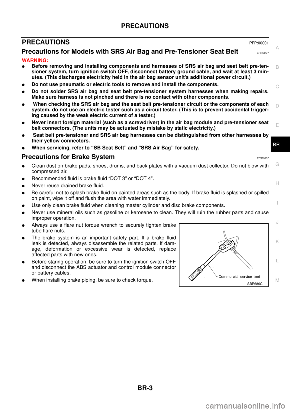
lAlways use a flare nut torque wrench to securely tighten brake
tube flare nuts.
lThe brake system is an important safety part. If a brake fluid
leak is detected, always disassemble the related parts. If dam-
age, deformation or excessive wear is detected, replace
affected parts with new ones.
lBefore staring operation, be sure to turn the ignition switch OFF
and disconnect the ABS actuator and control module connector
or battery cables.
lWhen installing brake piping, be sure to check torque.SBR686C
Page 839 of 3066

NOISE, VIBRATION, AND HARSHNESS (NVH) TROUBLESHOOTING
BR-5
C
D
E
G
H
I
J
K
L
MA
B
BR
NOISE, VIBRATION, AND HARSHNESS (NVH) TROUBLESHOOTINGPFP:00003
NVH Troubleshooting ChartEFS000TK
Use the chart below to help you find the cause of the symptom. If necessary, repair or replace these parts.
X: ApplicableReference page
BR-21
,BR-27
BR-21
,BR-27
.
BR-21
,BR-27—
—
BR-24,BR-30—
—
—
BR-25BR-31—
NVHinPRsection
NHV in RFD section
NVH in FAX,RAX and FSU,RSU section
NVH in WT section
NVH in WT section
NVH in RAX section
NVH in PS section
Possible cause and
SUSPECTED PARTS
Pads - damaged
Pads - uneven wear
Shims damaged
Rotor imbalance
Rotor damage
Rotor runout
Rotor deformation
Rotor deflection
Rotor rust
Rotor thickness variation
Drum out of round
PROPELLER SHAFT
DIFFERENTIAL
AXLE AND SUSPENSION
TIRES
ROAD WHEEL
DRIVE SHAFT
STEERING
Symptom BRAKENoise´´´ ´´ ´´´
´´
Shake´ ´ ´´´
´´
Shimmy, Judder´´´´´´´ ´´´ ´
Page 844 of 3066
BR-10
BRAKE FLUID
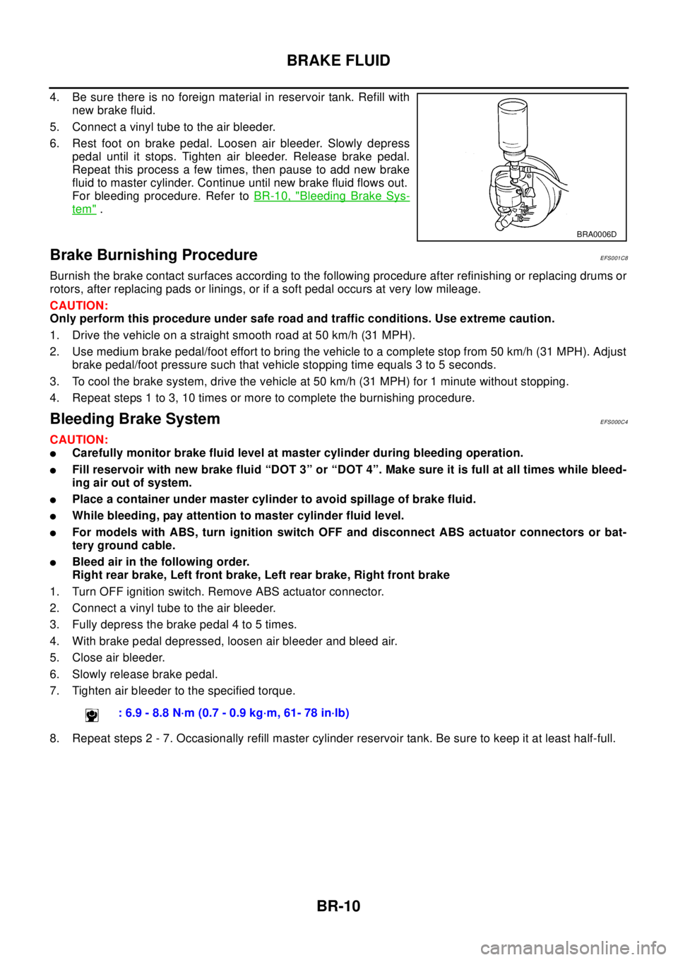
4. Be sure there is no foreign material in reservoir tank. Refill with
new brake fluid.
5. Connect a vinyl tube to the air bleeder.
6. Rest foot on brake pedal. Loosen air bleeder. Slowly depress
pedal until it stops. Tighten air bleeder. Release brake pedal.
Repeat this process a few times, then pause to add new brake
fluid to master cylinder. Continue until new brake fluid flows out.
For bleeding procedure. Refer toBR-10, "
Bleeding Brake Sys-
tem".
Brake Burnishing ProcedureEFS001C8
Burnish the brake contact surfaces according to the following procedure after refinishing or replacing drums or
rotors, after replacing pads or linings, or if a soft pedal occurs at very low mileage.
CAUTION:
Only perform this procedure under safe road and traffic conditions. Use extreme caution.
1. Drive the vehicle on a straight smooth road at 50 km/h (31 MPH).
2. Use medium brake pedal/foot effort to bring the vehicle to a complete stop from 50 km/h (31 MPH). Adjust
brake pedal/foot pressure such that vehicle stopping time equals 3 to 5 seconds.
3. To cool the brake system, drive the vehicle at 50 km/h (31 MPH) for 1 minute without stopping.
4. Repeat steps 1 to 3, 10 times or more to complete the burnishing procedure.
Bleeding Brake SystemEFS000C4
CAUTION:
lCarefully monitor brake fluid level at master cylinder during bleeding operation.
lFill reservoir with new brake fluid “DOT 3” or “DOT 4”. Make sure it is full at all times while bleed-
ing air out of system.
lPlace a container under master cylinder to avoid spillage of brake fluid.
lWhile bleeding, pay attention to master cylinder fluid level.
lFor models with ABS, turn ignition switch OFF and disconnect ABS actuator connectors or bat-
tery ground cable.
lBleed air in the following order.
Right rear brake, Left front brake, Left rear brake, Right front brake
1. Turn OFF ignition switch. Remove ABS actuator connector.
2. Connect a vinyl tube to the air bleeder.
3. Fully depress the brake pedal 4 to 5 times.
4. With brake pedal depressed, loosen air bleeder and bleed air.
5. Close air bleeder.
6. Slowly release brake pedal.
7. Tighten air bleeder to the specified torque.
8. Repeat steps 2 - 7. Occasionally refill master cylinder reservoir tank. Be sure to keep it at least half-full.
BRA0006D
: 6.9 - 8.8 N·m (0.7 - 0.9 kg·m, 61- 78 in·lb)
Page 855 of 3066
FRONT DISC BRAKE
BR-21
C
D
E
G
H
I
J
K
L
MA
B
BR
FRONT DISC BRAKEPFP:41000
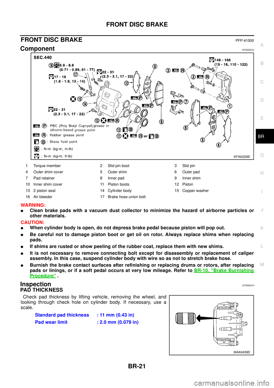
ComponentEFS000CG
WA RN ING:
lClean brake pads with a vacuum dust collector to minimize the hazard of airborne particles or
other materials.
CAUTION:
lWhen cylinder body is open, do not depress brake pedal because piston will pop out.
lBe careful not to damage piston boot or get oil on rotor. Always replace shims when replacing
pads.
lIf shims are rusted or show peeling of the rubber coat, replace them with new shims.
lIt is not necessary to remove connecting bolt except for disassembly or replacement of caliper
assembly. In this case, suspend cylinder body with wire so as not to stretch brake hose.
lBurnish the brake contact surfaces after refinishing or replacing drums or rotors, after replacing
pads or linings, or if a soft pedal occurs at very low mileage. Refer toBR-10, "
Brake Burnishing
Procedure".
InspectionEFS000CH
PAD THICKNESS
Check pad thickness by lifting vehicle, removing the wheel, and
looking through check hole on cylinder body. If necessary, use a
scale.
SFIA0328E
1 Torque member 2 Slid pin boot 3 Slid pin
4 Outer shim cover 5 Outer shim 6 Outer pad
7 Pad retainer 8 Inner pad 9 Inner shim
10 Inner shim cover 11 Piston boots 12 Piston
13 2 piston seal 14 Cylinder body 15 Copper washer
16 Air bleeder 17 Brake hose union bolt
Standard pad thickness : 11 mm (0.43 in)
Pad wear limit : 2.0 mm (0.079 in)
MAA0439D
Page 856 of 3066

BR-22
FRONT DISC BRAKE
Pad Replacement
EFS000CI
REMOVAL
CAUTION:
When replacing brake pads, always replace inner shims, outer shims, and shim covers as a set.
1. Remove master cylinder reservoir tank cap.
2. Remove lower sliding pin bolt.
3. Hang cylinder body with a wire, and remove pads, pad retainers,
shims and pad return springs.
INSTALLATION
1. Apply brake grease on back of the pad and both sides of the shim. Install inner shim and inner shim cover
to inner pad, outer shim to outer pad.
2. Apply brake grease on the pad retainer pad contact surface. Install pad retainers, pads and pad return
springs to the torque member.
3. Connect cylinder body to the torque member.
CAUTION:
When replacing pads with new ones, press piston in until the pads can be installed. Carefully mon-
itor brake master cylinder reservoir fluid level. Brake fluid will return, raising master cylinder res-
ervoir tank fluid level.
4. Insert lower sliding pin bolt and tighten to the specified torque.
5. Check brakes for drag.
Caliper Removal and InstallationEFS000CJ
REMOVAL
1. Connect a vinyl tube to the air bleeder.
2. Drain brake fluid gradually from air bleeder while depressing brake pedal.
SBR433D
SBR932C
Page 859 of 3066
FRONT DISC BRAKE
BR-25
C
D
E
G
H
I
J
K
L
MA
B
BR
Thickness Inspection
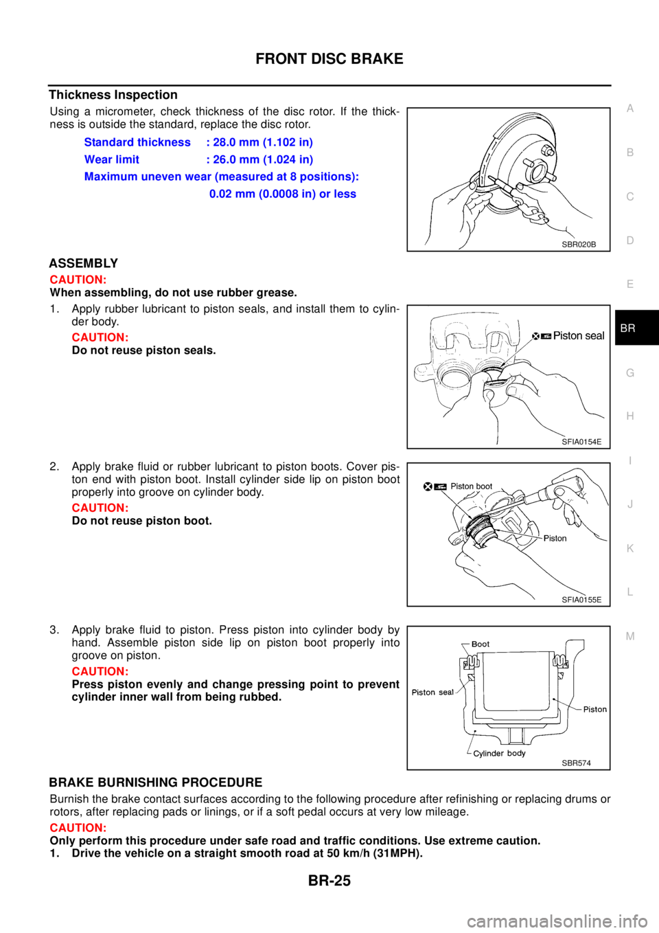
Using a micrometer, check thickness of the disc rotor. If the thick-
ness is outside the standard, replace the disc rotor.
ASSEMBLY
CAUTION:
When assembling, do not use rubber grease.
1. Apply rubber lubricant to piston seals, and install them to cylin-
der body.
CAUTION:
Do not reuse piston seals.
2. Apply brake fluid or rubber lubricant to piston boots. Cover pis-
ton end with piston boot. Install cylinder side lip on piston boot
properly into groove on cylinder body.
CAUTION:
Do not reuse piston boot.
3. Apply brake fluid to piston. Press piston into cylinder body by
hand. Assemble piston side lip on piston boot properly into
groove on piston.
CAUTION:
Press piston evenly and change pressing point to prevent
cylinder inner wall from being rubbed.
BRAKE BURNISHING PROCEDURE
Burnish the brake contact surfaces according to the following procedure after refinishing or replacing drums or
rotors, after replacing pads or linings, or if a soft pedal occurs at very low mileage.
CAUTION:
Only perform this procedure under safe road and traffic conditions. Use extreme caution.
1. Drive the vehicle on a straight smooth road at 50 km/h (31MPH).Standard thickness : 28.0 mm (1.102 in)
Wear limit : 26.0 mm (1.024 in)
Maximum uneven wear (measured at 8 positions):
0.02 mm (0.0008 in) or less
SBR020B
SFIA0154E
SFIA0155E
SBR574
Page 861 of 3066
REAR DISC BRAKE
BR-27
C
D
E
G
H
I
J
K
L
MA
B
BR
REAR DISC BRAKEPFP:44000
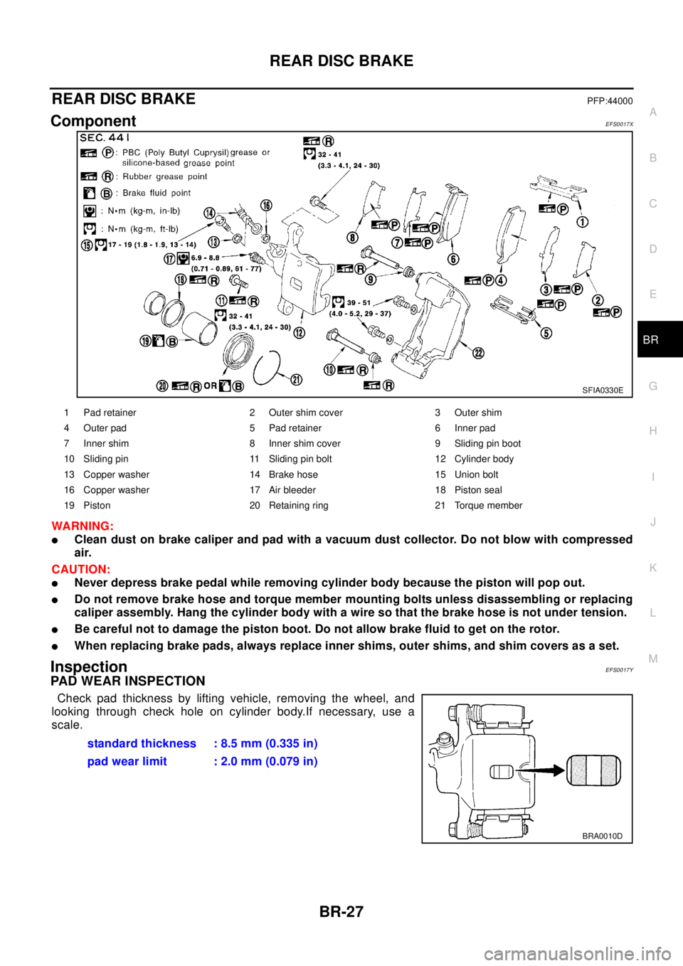
ComponentEFS0017X
WA RN ING:
lClean dust on brake caliper and pad with a vacuum dust collector. Do not blow with compressed
air.
CAUTION:
lNever depress brake pedal while removing cylinder body because the piston will pop out.
lDo not remove brake hose and torque member mounting bolts unless disassembling or replacing
caliper assembly. Hang the cylinder body with a wire so that the brake hose is not under tension.
lBe careful not to damage the piston boot. Do not allow brake fluid to get on the rotor.
lWhen replacing brake pads, always replace inner shims, outer shims, and shim covers as a set.
InspectionEFS0017Y
PAD WEAR INSPECTION
Check pad thickness by lifting vehicle, removing the wheel, and
looking through check hole on cylinder body.If necessary, use a
scale.
SFIA0330E
1 Pad retainer 2 Outer shim cover 3 Outer shim
4 Outer pad 5 Pad retainer 6 Inner pad
7 Inner shim 8 Inner shim cover 9 Sliding pin boot
10 Sliding pin 11 Sliding pin bolt 12 Cylinder body
13 Copper washer 14 Brake hose 15 Union bolt
16 Copper washer 17 Air bleeder 18 Piston seal
19 Piston 20 Retaining ring 21 Torque member
standard thickness : 8.5 mm (0.335 in)
pad wear limit : 2.0 mm (0.079 in)
BRA0010D
Page 862 of 3066
BR-28
REAR DISC BRAKE
Pad Replacement
EFS0017Z
REMOVAL
CAUTION:
When replacing brake pads, always replace inner shims, outer shims, and shim covers as a set.
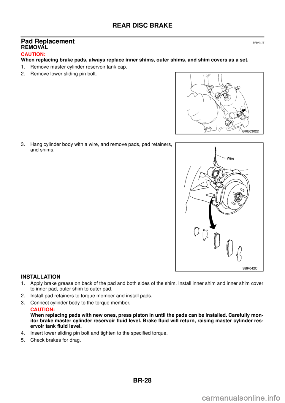
1. Remove master cylinder reservoir tank cap.
2. Remove lower sliding pin bolt.
3. Hang cylinder body with a wire, and remove pads, pad retainers,
and shims.
INSTALLATION
1. Apply brake grease on back of the pad and both sides of the shim. Install inner shim and inner shim cover
to inner pad, outer shim to outer pad.
2. Install pad retainers to torque member and install pads.
3. Connect cylinder body to the torque member.
CAUTION:
When replacing pads with new ones, press piston in until the pads can be installed. Carefully mon-
itor brake master cylinder reservoir fluid level. Brake fluid will return, raising master cylinder res-
ervoir tank fluid level.
4. Insert lower sliding pin bolt and tighten to the specified torque.
5. Check brakes for drag.
BRB0302D
SBR042C