2003 NISSAN X-TRAIL brake pads
[x] Cancel search: brake padsPage 863 of 3066

REAR DISC BRAKE
BR-29
C
D
E
G
H
I
J
K
L
MA
B
BR
Caliper Removal and InstallationEFS00180
REMOVAL
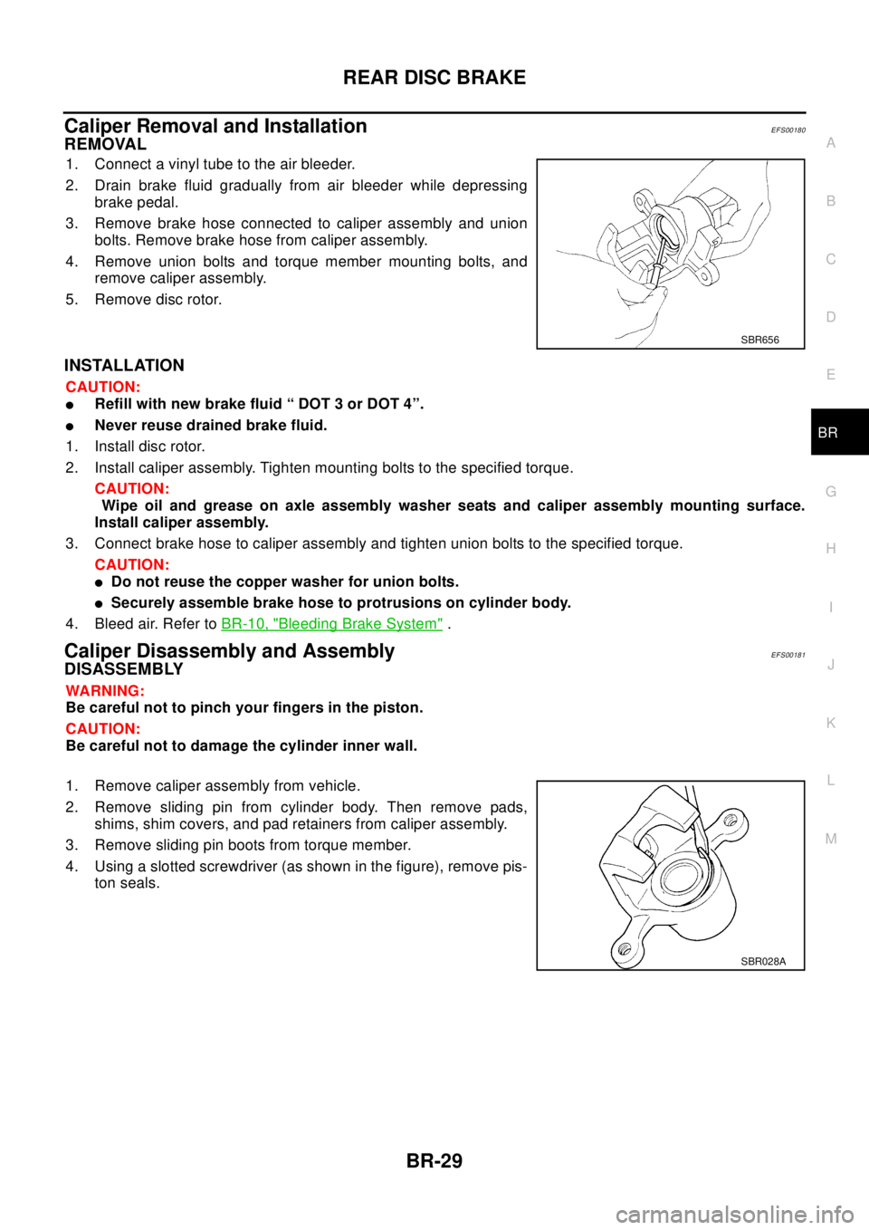
1. Connect a vinyl tube to the air bleeder.
2. Drain brake fluid gradually from air bleeder while depressing
brake pedal.
3. Remove brake hose connected to caliper assembly and union
bolts. Remove brake hose from caliper assembly.
4. Remove union bolts and torque member mounting bolts, and
remove caliper assembly.
5. Remove disc rotor.
INSTALLATION
CAUTION:
lRefill with new brake fluid “ DOT 3 or DOT 4”.
lNever reuse drained brake fluid.
1. Install disc rotor.
2. Install caliper assembly. Tighten mounting bolts to the specified torque.
CAUTION:
Wipe oil and grease on axle assembly washer seats and caliper assembly mounting surface.
Install caliper assembly.
3. Connect brake hose to caliper assembly and tighten union bolts to the specified torque.
CAUTION:
lDo not reuse the copper washer for union bolts.
lSecurely assemble brake hose to protrusions on cylinder body.
4. Bleed air. Refer toBR-10, "
Bleeding Brake System".
Caliper Disassembly and AssemblyEFS00181
DISASSEMBLY
WA RN ING:
Be careful not to pinch your fingers in the piston.
CAUTION:
Be careful not to damage the cylinder inner wall.
1. Remove caliper assembly from vehicle.
2. Remove sliding pin from cylinder body. Then remove pads,
shims, shim covers, and pad retainers from caliper assembly.
3. Remove sliding pin boots from torque member.
4. Using a slotted screwdriver (as shown in the figure), remove pis-
ton seals.
SBR656
SBR028A
Page 866 of 3066

BR-32
REAR DISC BRAKE
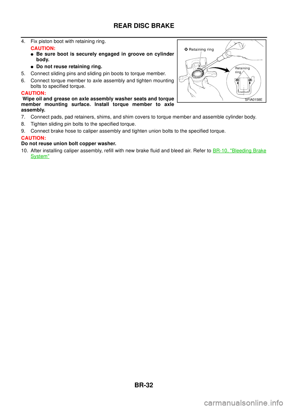
4. Fix piston boot with retaining ring.
CAUTION:
lBe sure boot is securely engaged in groove on cylinder
body.
lDo not reuse retaining ring.
5. Connect sliding pins and sliding pin boots to torque member.
6. Connect torque member to axle assembly and tighten mounting
bolts to specified torque.
CAUTION:
Wipe oil and grease on axle assembly washer seats and torque
member mounting surface. Install torque member to axle
assembly.
7. Connect pads, pad retainers, shims, and shim covers to torque member and assemble cylinder body.
8. Tighten sliding pin bolts to the specified torque.
9. Connect brake hose to caliper assembly and tighten union bolts to the specified torque.
CAUTION:
Do not reuse union bolt copper washer.
10. After installing caliper assembly, refill with new brake fluid and bleed air. Refer toBR-10, "
Bleeding Brake
System"
SFIA0158E
Page 867 of 3066

SERVICE DATA AND SPECIFICATIONS (SDS)
BR-33
C
D
E
G
H
I
J
K
L
MA
B
BR
SERVICE DATA AND SPECIFICATIONS (SDS)PFP:00030
General SpecificationsEFS000CQ
Brake PedalEFS000CR
Check ValveEF S0 00 CS
Brake BoosterEFS000CT
Vacuum type
Front Disc BrakeEFS000CU
Front brakeBrake model AD31VD
Cylinder bore diameter 44.4´2(1.748´0.08)
Pad
Length x width x thickness132.0´52.5´11 . 0
(5.20´2.067´0.433)
Rotor outer diameter x thickness 280´28 (11.02´1.10)
Rear brakeBrake model ADV9VA
Cylinder bore diameter 34.9 (1.374)
Pad
Length x width x thickness83.0´33.0´8.5
(3.268´1.299´0.335)
Rotor outer diameter x thickness 292´16 (11.50´0.63)
Master cylinder Cylinder bore diameter 25.4 (1)
Control valve Valve model Electronic control type
Brake booster Booster model C215T
Diaphragm diameterPrimary 230 (9.06)
Secondary 205 (8.07)
Recommended brake fluid DOT 3 or DOT 4
Free play (at pedal top surface) 3 - 11 mm (0.12 - 0.43 in)
Looseness at clevis pin (at pedal top surface) 1 - 3 mm (0.04 - 0.12 in)
Brake pedal height (from dash panel top surface)M/T model 156 - 166 mm (6.14 - 6.54 in)
A/T model 164 - 174 mm (6.46 - 6.85 in)
Depressed pedal height under force of 490 N (50 kg,110.6 lb)
(from dash panel top surface)M/T model 80 mm (3.15 in) or more
A/T model 85 mm (3.35 in) or more
Clearance between threaded end of stop lamp switch and pedal stopper 0.74 - 1.96 mm (0.0291 - 0.0772 in)
Vacuum leakage [at vacuum of 66.7 kPa (-500 mmHg, -19.69
inHg)]Within 1.3 kPa (10 mmHg, 0.39 inHg) of vacuum for 15 sec-
onds
Vacuum leakage [at vacuum of -66.7 kPa (-500 mmHg, -19.69
inHg)]Within 3.3 kPa (25 mmHg, 0.98 inHg) of vacuum for 15 sec-
onds
Input rod installation standard dimension 125 mm (4.92 in)
Brake typeAD31VD
Brake padStandard thickness (new) 11 mm (0.43 in)
Repair limit thickness 2.0 mm (0.07 in)
Disc rotorStandard thickness (new) 28 mm (1.10 in)
Repair limit thickness 26 mm (1.02 in)
Runout limit 0.04 mm (0.0016 in)
Page 868 of 3066

BR-34
SERVICE DATA AND SPECIFICATIONS (SDS)
Rear Disc Brake
EFS000CV
Brake typeAD9VA
Brake padStandard thickness (new) 8.5 mm (0.335 in)
Repair limit thickness 2.0 mm (0.079 in)
Disc rotorStandard thickness (new) 16 mm (0.63 in)
Repair limit thickness 14 mm (0.55 in)
Runout limit 0.07 mm (0.0028 in)
Page 872 of 3066
![NISSAN X-TRAIL 2003 Electronic Repair Manual BRC-4
[4WD/ABS]
PRECAUTIONS
[4WD/ABS]PRECAUTIONSPFP:00001
Precautions for brake systemEFS001B6
lRecommended fluid is brake fluid “DOT 3 ”or “DOT 4”.
lNever reuse drained brake fluid.
lBe caref NISSAN X-TRAIL 2003 Electronic Repair Manual BRC-4
[4WD/ABS]
PRECAUTIONS
[4WD/ABS]PRECAUTIONSPFP:00001
Precautions for brake systemEFS001B6
lRecommended fluid is brake fluid “DOT 3 ”or “DOT 4”.
lNever reuse drained brake fluid.
lBe caref](/manual-img/5/57402/w960_57402-871.png)
BRC-4
[4WD/ABS]
PRECAUTIONS
[4WD/ABS]PRECAUTIONSPFP:00001
Precautions for brake systemEFS001B6
lRecommended fluid is brake fluid “DOT 3 ”or “DOT 4”.
lNever reuse drained brake fluid.
lBe careful not to splash brake fluid on painted areas.
lTo clean or wash all parts of master cylinder, disc brake caliper and wheel cylinder, use clean brake fluid.
lNever use mineral oils such as gasoline or kerosene. They will ruin rubber parts of the hydraulic system.
lUse flare nut wrench when removing and installing brake tube.
lAlways torque brake lines when installing.
lBurnish the brake contact surfaces after refinishing or replacing
drums or rotors, after replacing pads or linings, or if a soft pedal
occurs at very low mileage. Refer toBR-10, "
Brake Burnishing
Procedure".
lBefore working, turn OFF ignition switch. Disconnect connectors
for ABS actuator and control module or battery terminals.
WAR NIN G:
lClean brake pads and shoes with a waste cloth, then wipe
with a dust collector.
Precautions for brake controlEFS001B7
lIf malfunction is indicated by 4WD warning lamp and/or ABS warning lamp, collect necessary information
from customer (what symptoms are present under what conditions). Find out possible causes before start-
ing service. Besides electrical system inspection, check operation of ABS actuator.
lIf malfunction is detected, proceed to trouble diagnosis after checking tire pressure and tire wear.
lStopping distance or steering stability may be deteriorated by the following conditions. Tire size and type
are in improper combination. Brake pads are not Nissan genuine parts.
lFitting tires of different size on vehicle can be cause of longitudinal vibration. Always use tires of the same
size and brand. Exchange front and rear tires on the following conditions: Longitudinal vibration occurs in
vehicle with tires of the same size and brand. After replacement, perform trouble diagnosis. 1580|None
l4WD/ABS function may have a failure or error under following condition: There is radio, antenna, or
antenna lead-in wire (including wiring) near control module.
lIf aftermarket parts (e.g. Car stereo equipment, CD player) have been installed, check electrical har-
nesses for pinches, open, and improper wiring.
SBR686C
Page 920 of 3066
![NISSAN X-TRAIL 2003 Electronic Repair Manual BRC-52
[ESP/TCS/ABS]
PRECAUTIONS
[ESP/TCS/ABS]PRECAUTIONSPFP:00001
Precautions for Supplemental Restraint System (SRS) “AIR BAG” and “SEAT
BELT PRE-TENSIONER”
EFS0019N
The Supplemental Restrai NISSAN X-TRAIL 2003 Electronic Repair Manual BRC-52
[ESP/TCS/ABS]
PRECAUTIONS
[ESP/TCS/ABS]PRECAUTIONSPFP:00001
Precautions for Supplemental Restraint System (SRS) “AIR BAG” and “SEAT
BELT PRE-TENSIONER”
EFS0019N
The Supplemental Restrai](/manual-img/5/57402/w960_57402-919.png)
BRC-52
[ESP/TCS/ABS]
PRECAUTIONS
[ESP/TCS/ABS]PRECAUTIONSPFP:00001
Precautions for Supplemental Restraint System (SRS) “AIR BAG” and “SEAT
BELT PRE-TENSIONER”
EFS0019N
The Supplemental Restraint System such as “AIR BAG” and “SEAT BELT PRE-TENSIONER”, used along
with a front seat belt, helps to reduce the risk or severity of injury to the driver and front passenger for certain
types of collision. Information necessary to service the system safely is included in the SRS and SB section of
this Service Manual.
WAR NIN G:
lTo avoid rendering the SRS inoperative, which could increase the risk of personal injury or death
in the event of a collision which would result in air bag inflation, all maintenance must be per-
formed by an authorized NISSAN/INFINITI dealer.
lImproper maintenance, including incorrect removal and installation of the SRS, can lead to per-
sonal injury caused by unintentional activation of the system. For removal of Spiral Cable and Air
Bag Module, see the SRS section.
lDo not use electrical test equipment on any circuit related to the SRS unless instructed to in this
Service Manual. SRS wiring harnesses can be identified by yellow harness connector.
Precautions for Brake SystemEFS0019O
lRecommended fluid is brake fluid “DOT 3” or “DOT 4”.
lNever reuse drained brake fluid.
lBe careful not to splash brake fluid on painted areas; it may cause paint damage. If brake fluid is splashed
on painted areas, wash it away with water immediately.
lNever use mineral oils such as gasoline or kerosene. They will ruin rubber parts of hydraulic system.
lUse flare nut wrench when removing and installing brake tubes.
lAlways torque brake lines when installing.
lBefore working, turn the ignition switch OFF and disconnect the
connectors for the ESP/TCS/ABS actuator and control unit or
the battery terminals.
lBurnish the brake contact surfaces after refinishing or replacing
drums or rotors, after replacing pads or linings, or if a soft pedal
occurs at very low mileage. Refer toBR-10, "
Brake Burnishing
Procedure".
WAR NIN G:
Clean brakes with a vacuum dust collector to minimize risk
of health hazard from powder caused by friction.
Precautions for Brake ControlEFS0019P
lDuring the EPS/TCS/ABS operation, the brake pedal vibrates lightly and its mechanical noise may be
heard. This is a normal condition.
lJust after starting the vehicle after ignition switch ON, the brake pedal may vibrate or the motor operating
noise may be heard from the engine compartment. This is a normal status of the operation check.
lThe stopping distance may be longer than that of vehicles without ABS when the vehicle drives on rough,
gravel, or snowy (fresh deep snow) road.
lIf a malfunction is indicated by the ABS warning lamp, or other warning lamps, collect the necessary infor-
mation from the customer (what symptoms are present under what conditions) and find out the possible
causes before starting the service. Besides the electrical system inspection, check the booster operation,
brake fluid level, and oil leaks.
lIf the tire size and type are used in a improper combination, or the brake pads are not NISSAN genuine
parts, the stopping distance or steering stability may deteriorate.
lIf there is a radio, antenna, or antenna lead-in wire (including wiring) near the control unit, the ESP/TCS/
ABS function may have a malfunction or error.
lIf aftermarket parts (e.g. Car stereo equipment, CD player) have been installed, check the electrical har-
nesses for pinches, open, and improper wiring.
SBR686C
Page 957 of 3066
![NISSAN X-TRAIL 2003 Electronic Repair Manual TROUBLE DIAGNOSIS
BRC-89
[ESP/TCS/ABS]
C
D
E
G
H
I
J
K
L
MA
B
BRC
ABS Warning Lamp, ESP OFF Indicator Lamp, SLIP Indicator Lamp ON/OFF Timing
´:ON –: Lamp OFF
´: Applicable
–: Not applicable
Bas NISSAN X-TRAIL 2003 Electronic Repair Manual TROUBLE DIAGNOSIS
BRC-89
[ESP/TCS/ABS]
C
D
E
G
H
I
J
K
L
MA
B
BRC
ABS Warning Lamp, ESP OFF Indicator Lamp, SLIP Indicator Lamp ON/OFF Timing
´:ON –: Lamp OFF
´: Applicable
–: Not applicable
Bas](/manual-img/5/57402/w960_57402-956.png)
TROUBLE DIAGNOSIS
BRC-89
[ESP/TCS/ABS]
C
D
E
G
H
I
J
K
L
MA
B
BRC
ABS Warning Lamp, ESP OFF Indicator Lamp, SLIP Indicator Lamp ON/OFF Timing
´:ON –: Lamp OFF
´: Applicable
–: Not applicable
Basic InspectionEFS001A9
PRELIMINARY CHECK 1: (BRAKE FLUID LEVEL AND LEAK INSPECTION)
1. Check the fluid level in the brake reservoir tank. If the fluid level is low, refill the brake fluid.
2. Check the area around the brake piping, ESP/TCS/ABS actuator for leaks. If a leak or oozing is detected,
checkasfollows:
lIf the connections at the ESP/TCS/ABS actuator are loose, tighten the piping to the specified torque.
Then check again for leaks, and make sure that there is no fluid leak.
lIf the flare nuts at the connections and the threads of the ESP/TCS/ABS actuator are damaged, replace
the damaged parts. Then check again for leaks, and make sure that there is no fluid leak.
lIf a leak or oozing is detected on other parts than the ESP/TCS/ABS actuator connections, wipe the
applicable part with a clean cloth. Then check again for leaks, and if there is still a leak or oozing,
replace the damaged part.
lIf a leak or oozing is detected on the ESP/TCS/ABS actuator body, wipe the applicable part with a clean
cloth. Then check again for leaks, and if there is still a leak or oozing, replace the ESP/TCS/ABS actua-
tor body.
CAUTION:
Do not disassemble the actuator body.
3. Check the brake disc rotor and pads.
PRELIMINARY CHECK 2: (INSPECTION FOR LOOSE POWER SUPPLY TERMINAL)
Check the battery for looseness on the battery positive/negative terminals and ground connection. If loose-
ness is detected, tighten the piping to the specified torque. Check that the battery voltage does not drop and
the alternator is normal.
PRELIMINARY CHECK 3: (INSPECTION FOR ABS WARNING LAMP, ESP OFF INDICATOR
LAMP, AND SLIP INDICATOR LAMP)
1. Check that the ABS warning lamp is ON for Approx. 0.5 seconds when the ignition switch is turned ON. If
it does not turn on, check the ABS warning lamp and the circuit, and the combination meter.
2. Check that ESP OFF indicator lamp is ON for Approx. 0.5 seconds when the ignition switch is turned ON.
If it does not turn ON, check the ESP OFF indicator lamp and the circuit, and the combination meter.
3. Check that the SLIP indicator lamp is ON for Approx. 0.5 seconds when the ignition switch is turned ON. If
it does not turn ON, check the SLIP indicator lamp and the circuit.
Condition ABS warning lampESP OFF
indicator lampSLIP indicator lamp Remarks
When the ignition switch is
OFF––– –
After the ignition switch is
turned ON
For Approx. 0.5 seconds´´´–
Ignition switch ON
Approx. 0.5 seconds later––– –
When the ESP OFF switch
turns ON (ESP/TCS function
OFF).–´–Lamp goes off after Approx. 2
seconds when the engine re-start.
ESP/TCS/ABS
malfunction´´´–
´´–When the ESP/TCS/ABS control
unit is abnormal (power supply or
ground malfunction).
When the ESP/TCS ism
abnormal.–´´–
Page 2500 of 3066

MA-8
PERIODIC MAINTENANCE
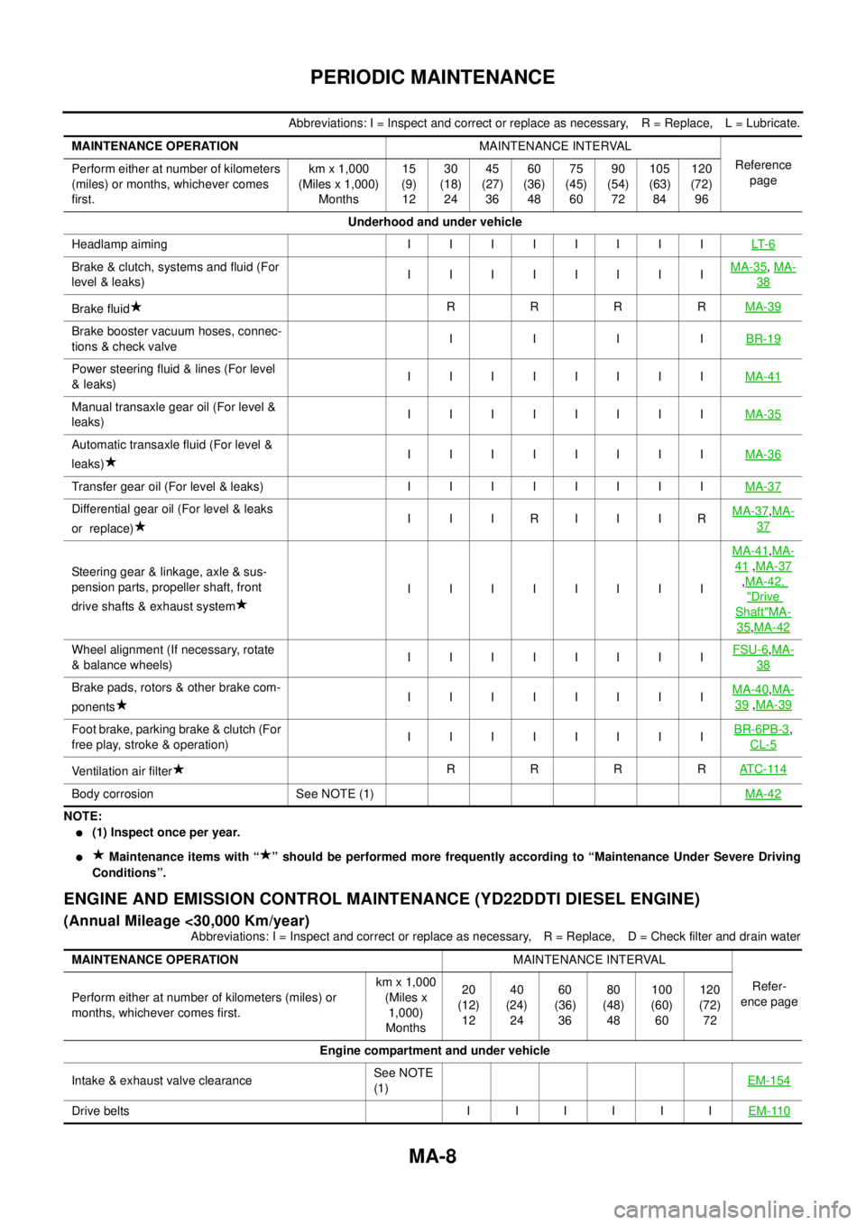
Abbreviations: I = Inspect and correct or replace as necessary, R = Replace, L = Lubricate.
NOTE:
l(1) Inspect once per year.
lMaintenance items with “ ” should be performed more frequently according to “Maintenance Under Severe Driving
Conditions”.
ENGINE AND EMISSION CONTROL MAINTENANCE (YD22DDTI DIESEL ENGINE)
(Annual Mileage <30,000 Km/year)
Abbreviations: I = Inspect and correct or replace as necessary, R = Replace, D = Check filter and drain water MAINTENANCE OPERATIONMAINTENANCE INTERVAL
Reference
page Perform either at number of kilometers
(miles) or months, whichever comes
first.km x 1,000
(Miles x 1,000)
Months15
(9)
1230
(18)
2445
(27)
3660
(36)
4875
(45)
6090
(54)
72105
(63)
84120
(72)
96
Underhood and under vehicle
Headlampaiming IIIIIIIILT- 6
Brake & clutch, systems and fluid (For
level & leaks)IIIIIIIIMA-35,MA-
38
Brake fluidRRRRMA-39
Brake booster vacuum hoses, connec-
tions & check valveIIIIBR-19
Power steering fluid & lines (For level
&leaks)IIIIIIIIMA-41
Manual transaxle gear oil (For level &
leaks)IIIIIIIIMA-35
Automatic transaxle fluid (For level &
leaks)IIIIIIIIMA-36
Transfer gear oil (For level & leaks) I I I I I I I IMA-37
Differential gear oil (For level & leaks
or replace)I I IRI I IRMA-37,MA-
37
Steering gear & linkage, axle & sus-
pension parts, propeller shaft, front
drive shafts & exhaust systemIIIIIIIIMA-41
,MA-
41,MA-37
,MA-42,
"Drive
Shaft"MA-
35,MA-42
Wheel alignment (If necessary, rotate
& balance wheels)IIIIIIIIFSU-6,MA-
38
Brake pads, rotors & other brake com-
ponentsIIIIIIIIMA-40,MA-
39,MA-39
Foot brake, parking brake & clutch (For
free play, stroke & operation)IIIIIIIIBR-6PB-3,
CL-5
Ventilation air filterRRRRAT C - 11 4
Body corrosion See NOTE (1)MA-42
MAINTENANCE OPERATIONMAINTENANCE INTERVAL
Refer-
ence page Perform either at number of kilometers (miles) or
months, whichever comes first.km x 1,000
(Miles x
1,000)
Months20
(12)
1240
(24)
2460
(36)
3680
(48)
48100
(60)
60120
(72)
72
Engine compartment and under vehicle
Intake & exhaust valve clearanceSee NOTE
(1)EM-154
Drivebelts IIIIIIEM-110