2003 NISSAN X-TRAIL fuel pressure
[x] Cancel search: fuel pressurePage 36 of 3066

AT-30
OVERALL SYSTEM
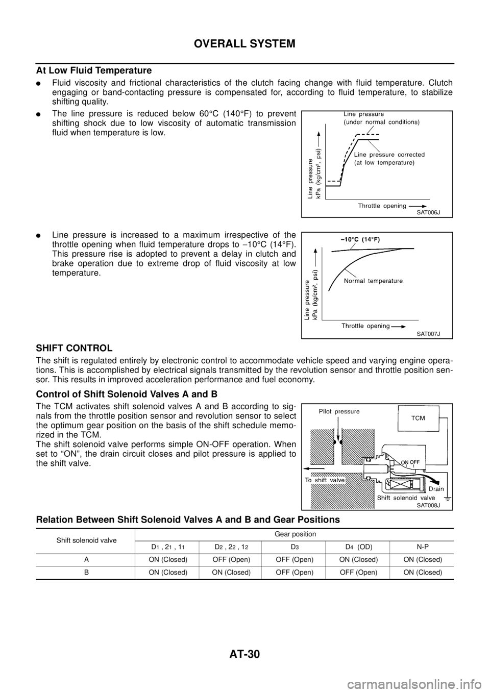
At Low Fluid Temperature
lFluid viscosity and frictional characteristics of the clutch facing change with fluid temperature. Clutch
engaging or band-contacting pressure is compensated for, according to fluid temperature, to stabilize
shifting quality.
lThe line pressure is reduced below 60°C(140°F) to prevent
shifting shock due to low viscosity of automatic transmission
fluid when temperature is low.
lLine pressure is increased to a maximum irrespective of the
throttle opening when fluid temperature drops to-10°C(14°F).
This pressure rise is adopted to prevent a delay in clutch and
brake operation due to extreme drop of fluid viscosity at low
temperature.
SHIFT CONTROL
The shift is regulated entirely by electronic control to accommodate vehicle speed and varying engine opera-
tions. This is accomplished by electrical signals transmitted by the revolution sensor and throttle position sen-
sor. This results in improved acceleration performance and fuel economy.
Control of Shift Solenoid Valves A and B
The TCM activates shift solenoid valves A and B according to sig-
nals from the throttle position sensor and revolution sensor to select
the optimum gear position on the basis of the shift schedule memo-
rizedintheTCM.
The shift solenoid valve performs simple ON-OFF operation. When
set to “ON”, the drain circuit closes and pilot pressure is applied to
the shift valve.
Relation Between Shift Solenoid Valves A and B and Gear Positions
SAT006J
SAT007J
SAT008J
Shift solenoid valveGear position
D1,21,11D2,22,12D3D4(OD) N-P
A ON (Closed) OFF (Open) OFF (Open) ON (Closed) ON (Closed)
B ON (Closed) ON (Closed) OFF (Open) OFF (Open) ON (Closed)
Page 925 of 3066
![NISSAN X-TRAIL 2003 Electronic Repair Manual GENERAL INFORMATION
BRC-57
[ESP/TCS/ABS]
C
D
E
G
H
I
J
K
L
MA
B
BRC
lWhen starting the engine, or just after starting the vehicle, the brake pedal may vibrate or the
motor operating noise may be heard NISSAN X-TRAIL 2003 Electronic Repair Manual GENERAL INFORMATION
BRC-57
[ESP/TCS/ABS]
C
D
E
G
H
I
J
K
L
MA
B
BRC
lWhen starting the engine, or just after starting the vehicle, the brake pedal may vibrate or the
motor operating noise may be heard](/manual-img/5/57402/w960_57402-924.png)
GENERAL INFORMATION
BRC-57
[ESP/TCS/ABS]
C
D
E
G
H
I
J
K
L
MA
B
BRC
lWhen starting the engine, or just after starting the vehicle, the brake pedal may vibrate or the
motor operating noise may be heard from the engine compartment. This is a normal status of the
operation check.
lThe stopping distance may be longer than that of vehicles without ABS when the vehicle drives on
rough, gravel, or snowy (fresh deep snow) road.
TCS FunctionsEFS0019V
1. With the wheel speed sensor signals from 4 wheels, the ESP/TCS/ABS control unit detects a wheel spin.
If a wheel spins, the control unit controls brake fluid pressure to the spinning wheel, and cuts the fuel to
the engine. It also closes the throttle valve to reduce the engine torque. Furthermore, throttle position is
controlled to the appropriate engine torque.
2. If a wheel spins, the TCS system works same as LSD (Limited Slip Differential) function applying brake
fluid pressure to the spinning wheel.
3. During TCS operation, it informs a driver of system operation by flashing SLIP indicator lamp.
CAUTION:
lDuring TCS operation, the body and the brake pedal lightly vibrate and the mechanical noise may
be heard. This is a normal condition.
lDepending on road circumstances, the driver may have a sluggish feel. This is not abnormal,
because the optimum traction has the highest priority by TCS operation.
lWhen the vehicle is passing through a road where the surface friction coefficient varies, down-
shifting or depressing the accelerator pedal fully may activate TCS temporarily.
ESP FunctionsEFS0019W
1. The Electronic Stability Program is called the ESP for short.
The ESP is indicated as the VDC (the Vehicle Dynamics Control) on the CONSULT-II screen.
2. In addition to the ABS/TCS function, ESP detects the driver's steering operation amount and brake opera-
tion amount from the steering angle sensor and pressure sensor. Using the information from the yaw rate/
side G sensor and wheel speed sensors, ESP judges the driving condition (conditions of understeer and
oversteer) to improve the stability by controlling the brake on 4 wheels and engine output.
3. During ESP operation, the SLIP indicator lamp flashes to inform the driver of the operation.
CAUTION:
lDuring ESP operation, the body and the brake pedal lightly vibrate and their mechanical noise
may be heard. This is a normal condition.
lIf the vehicle is rotated on a turn table, or rolled and rocked on a ship, the ABS warning lamp,
ESP OFF indicator lamp, and SLIP indicator lamp may turn ON. In this case, start the engine on a
normal road again. If the ABS warning lamp, ESP OFF indicator lamp, and SLIP indicator lamp
turn OFF after the restart, it is normal.
lWhen driving in a steep slope such as a bank, the ABS warning lamp, ESP OFF indicator lamp,
and SLIP indicator lamp may turn ON. In this case, start the engine on a normal road again. If the
ABS warning lamp, ESP OFF indicator lamp, and SLIP indicator lamp turn OFF after the restart, it
is normal.
Page 1056 of 3066

DI-2
Engine Models) ....................................................... 31
Inspection/Vehicle speed signal ............................. 32
Inspection/Fuel Level Sensor Unit .......................... 33
FUEL LEVEL SENSOR UNIT .............................. 33
LOW-FUEL WARNING LAMP ............................. 33
The Fuel Gauge Pointer Fluctuates·Indicator
Wrong Value·or Varies. ........................................... 35
The Fuel Gauge Does Not Move to F-position. ...... 36
The Fuel Gauge Does Not Work. ........................... 36
Low Fuel Warning Lamp Illuminate or Not Illuminate... 37
Electrical Components Inspection .......................... 37
FUEL LEVEL SENSOR UNIT CHECK / GASO-
LINE ENGINE MODELS ...................................... 37
FUEL LEVEL SENSOR UNIT CHECK / DIESEL
ENGINE MODELS ............................................... 37
THERMAL TRANSMITTER CHECK ................... 38
Removal and Installation for Combination Meter .... 38
Disassembly and Assembly for Combination Meter... 38
WARNING LAMPS .................................................... 39
Schematic ............................................................... 39
Wiring Diagram — WARN —/ LHD Models ............ 40Wiring Diagram — WARN — / RHD Models ...........45
Electrical Components Inspection ...........................50
FUEL WARNING LAMP OPERATION CHECK ... 50
OIL PRESSURE SWITCH CHECK ......................50
DIODE CHECK ....................................................50
A/T INDICATOR .........................................................51
Wiring Diagram — AT/IND — .................................51
WARNING CHIME .....................................................52
System Description .................................................52
POWER SUPPLY AND GROUND CIRCUIT .......52
IGNITION KEY WARNING CHIME ......................52
LIGHT WARNING CHIME ...................................52
Component Parts and Harness Connector Location... 53
Wiring Diagram — CHIME — .................................54
Symptom Chart .......................................................56
Power Supply and Ground Circuit Check ...............56
Lighting Switch Input Signal Check .........................57
Key Switch Insert Signal Check ..............................57
Door Unlock Sensor Check .....................................58
Front Door Switch (driver side) Check ....................59
CLOCK ......................................................................60
Wiring Diagram — CLOCK — .................................60
Page 1104 of 3066

DI-50
WARNING LAMPS
Electrical Components Inspection
EKS002HK
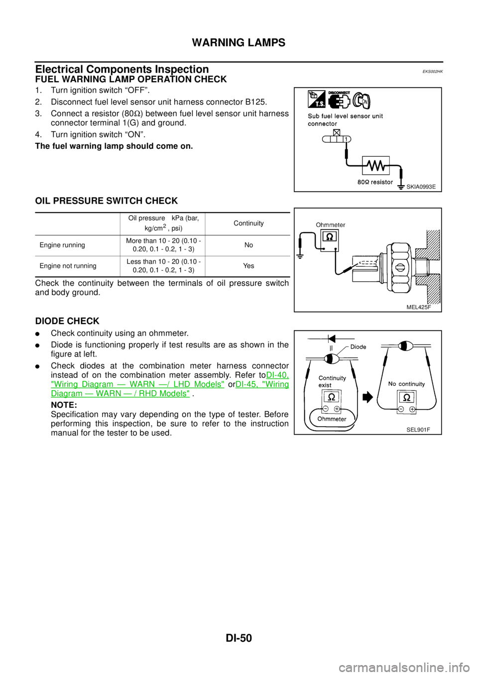
FUEL WARNING LAMP OPERATION CHECK
1. Turn ignition switch “OFF”.
2. Disconnect fuel level sensor unit harness connector B125.
3. Connect a resistor (80W) between fuel level sensor unit harness
connector terminal 1(G) and ground.
4. Turn ignition switch “ON”.
The fuel warning lamp should come on.
OIL PRESSURE SWITCH CHECK
Check the continuity between the terminals of oil pressure switch
and body ground.
DIODE CHECK
lCheck continuity using an ohmmeter.
lDiode is functioning properly if test results are as shown in the
figure at left.
lCheck diodes at the combination meter harness connector
instead of on the combination meter assembly. Refer toDI-40,
"Wiring Diagram—WARN—/LHDModels"orDI-45, "Wiring
Diagram—WARN—/RHDModels".
NOTE:
Specification may vary depending on the type of tester. Before
performing this inspection, be sure to refer to the instruction
manual for the tester to be used.
SKIA0993E
Oil pressure kPa (bar,
kg/cm2,psi)Continuity
Engine runningMore than 10 - 20 (0.10 -
0.20,0.1-0.2,1-3)No
Engine not runningLess than 10 - 20 (0.10 -
0.20,0.1-0.2,1-3)Ye s
MEL425F
SEL901F
Page 1115 of 3066

EC-1
ENGINE CONTROL SYSTEM
B ENGINE
CONTENTS
C
D
E
F
G
H
I
J
K
L
M
SECTION
A
EC
ENGINE CONTROL SYSTEM
QR (WITH EURO-OBD)
INDEX FOR DTC ...................................................... 12
Alphabetical Index .................................................. 12
DTC No. Index ....................................................... 14
PRECAUTIONS ........................................................ 16
Precautions for Supplemental Restraint System
(SRS) “AIR BAG” and “SEAT BELT PRE-TEN-
SIONER” ................................................................ 16
On Board Diagnostic (OBD) System of Engine and
A/T .......................................................................... 16
Precaution .............................................................. 16
Wiring Diagrams and Trouble Diagnosis ................ 19
PREPARATION ......................................................... 20
Special Service Tools ............................................. 20
Commercial Service Tools ...................................... 20
ENGINE CONTROL SYSTEM .................................. 22
System Diagram ..................................................... 22
Vacuum Hose Drawing ........................................... 23
System Chart ......................................................... 24
Multiport Fuel Injection (MFI) System .................... 24
Electronic Ignition (EI) System ............................... 27
Air Conditioning Cut Control ................................... 27
Fuel Cut Control (at No Load and High Engine
Speed) .................................................................... 28
CAN communication .............................................. 28
BASIC SERVICE PROCEDURE .............................. 30
Idle Speed and Ignition Timing Check .................... 30
Throttle Valve Closed Position Learning ................ 31
Accelerator Pedal Released Position Learning ...... 31
Idle Air Volume Learning ........................................ 31
Fuel Pressure Check .............................................. 34
ON BOARD DIAGNOSTIC (OBD) SYSTEM ............ 36
Introduction ............................................................ 36
Two Trip Detection Logic ........................................ 36
Emission-related Diagnostic Information ................ 37
NATS (Nissan Anti-theft System) ........................... 48
Malfunction Indicator (MI) ....................................... 48
OBD System Operation Chart ................................ 51
TROUBLE DIAGNOSIS ............................................ 57
Trouble Diagnosis Introduction ............................... 57DTC Inspection Priority Chart ................................. 61
Fail-safe Chart ........................................................ 62
Basic Inspection ..................................................... 64
Symptom Matrix Chart ............................................ 69
Engine Control Component Parts Location ............ 73
Circuit Diagram ....................................................... 77
ECM Harness Connector Terminal Layout ............. 79
ECM Terminals and Reference Value ..................... 79
CONSULT-II Function ............................................. 86
Generic Scan Tool (GST) Function ......................... 96
CONSULT-II Reference Value in Data Monitor ....... 97
Major Sensor Reference Graph in Data Monitor
Mode .....................................................................100
TROUBLE DIAGNOSIS - SPECIFICATION VALUE. 103
Description ............................................................103
Testing Condition ..................................................103
Inspection Procedure ............................................103
Diagnostic Procedure ...........................................104
TROUBLE DIAGNOSIS FOR INTERMITTENT INCI-
DENT .......................................................................107
Description ............................................................107
Diagnostic Procedure ...........................................107
POWER SUPPLY CIRCUIT FOR ECM ...................108
Wiring Diagram .....................................................108
ECM Terminals and Reference Value ...................109
Diagnostic Procedure ...........................................109
Component Inspection ..........................................113
DTC U1000 CAN COMMUNICATION LINE ............114
Description ............................................................114
On Board Diagnosis Logic ....................................114
DTC Confirmation Procedure ...............................114
Wiring Diagram .....................................................115
Diagnostic Procedure ...........................................116
DTC P0011 IVT CONTROL .....................................117
Description ............................................................117
CONSULT-II Reference Value in Data Monitor Mode
.117
ECM Terminals and Reference Value ...................117
On Board Diagnosis Logic ....................................118
Page 1119 of 3066

EC-5
C
D
E
F
G
H
I
J
K
L
M
ECA DTC P1805 BRAKE SWITCH ................................ 329
Description ........................................................... 329
CONSULT-II Reference Value in Data Monitor Mode
. 329
ECM Terminals and Reference Value .................. 329
On Board Diagnosis Logic ................................... 329
DTC Confirmation Procedure ............................... 329
Wiring Diagram .................................................... 330
Diagnostic Procedure ........................................... 331
Component Inspection ......................................... 332
IGNITION SIGNAL .................................................. 334
Component Description ........................................ 334
ECM Terminals and Reference Value .................. 334
Wiring Diagram .................................................... 335
Diagnostic Procedure ........................................... 337
Component Inspection ......................................... 341
Removal and Installation ...................................... 342
INJECTOR CIRCUIT ............................................... 343
Component Description ........................................ 343
CONSULT-II Reference Value in Data Monitor Mode
. 343
ECM Terminals and Reference Value .................. 343
Wiring Diagram .................................................... 344
Diagnostic Procedure ........................................... 345
Component Inspection ......................................... 347
Removal and Installation ...................................... 347
START SIGNAL ...................................................... 348
CONSULT-II Reference Value in Data Monitor Mode
. 348
ECM Terminals and Reference Value .................. 348
Wiring Diagram .................................................... 349
Diagnostic Procedure ........................................... 350
FUEL PUMP CIRCUIT ............................................ 352
Description ........................................................... 352
CONSULT-II Reference Value in Data Monitor Mode
. 352
ECM Terminals and Reference Value .................. 352
Wiring Diagram .................................................... 354
Diagnostic Procedure ........................................... 355
Component Inspection ......................................... 357
Removal and Installation ...................................... 358
REFRIGERANT PRESSURE SENSOR ................. 359
Component Description ........................................ 359
ECM Terminals and Reference Value .................. 359
Wiring Diagram .................................................... 360
Diagnostic Procedure ........................................... 361
Removal and Installation ...................................... 362
ELECTRICAL LOAD SIGNAL ................................ 363
CONSULT-II Reference Value in Data Monitor Mode
. 363
ECM Terminals and Reference Value .................. 363
Wiring Diagram .................................................... 364
Diagnostic Procedure ........................................... 366
DATA LINK CONNECTOR ..................................... 371
Wiring Diagram .................................................... 371
EVAPORATIVE EMISSION SYSTEM ..................... 372
Description ........................................................... 372
Component Inspection ......................................... 374POSITIVE CRANKCASE VENTILATION ...............375
Description ............................................................375
Component Inspection ..........................................375
SERVICE DATA AND SPECIFICATIONS (SDS) ....377
Fuel Pressure .......................................................377
Idle Speed and Ignition Timing .............................377
Calculated Load Value ..........................................377
Mass Air Flow Sensor ...........................................377
Intake Air Temperature Sensor .............................377
Engine Coolant Temperature Sensor ...................377
Heated Oxygen Sensor 1 Heater .........................377
Heated Oxygen sensor 2 Heater ..........................377
Crankshaft Position Sensor (POS) .......................377
Camshaft Position Sensor (PHASE) ....................377
Throttle Control Motor ...........................................378
Injector ..................................................................378
Fuel Pump ............................................................378
QR (WITHOUT EURO-OBD)
INDEX FOR DTC .....................................................379
Alphabetical Index ................................................379
DTC No. Index ......................................................380
PRECAUTIONS ......................................................381
Precautions for Supplemental Restraint System
(SRS) “AIR BAG” and “SEAT BELT PRE-TEN-
SIONER” ...............................................................381
On Board Diagnostic (OBD) System of Engine and
A/T ........................................................................381
Precaution ............................................................381
Wiring Diagrams and Trouble Diagnosis ..............384
PREPARATION .......................................................385
Special Service Tools ...........................................385
Commercial Service Tools ....................................385
ENGINE CONTROL SYSTEM ................................387
System Diagram ...................................................387
Vacuum Hose Drawing .........................................388
System Chart ........................................................389
Multiport Fuel Injection (MFI) System ...................389
Electronic Ignition (EI) System .............................392
Air Conditioning Cut Control .................................392
Fuel Cut Control (at No Load and High Engine
Speed) ..................................................................393
CAN communication .............................................393
BASIC SERVICE PROCEDURE .............................395
Idle Speed and Ignition Timing Check ..................395
Throttle Valve Closed Position Learning ...............396
Accelerator Pedal Released Position Learning ....396
Idle Air Volume Learning ......................................396
Fuel Pressure Check ............................................399
ON BOARD DIAGNOSTIC (OBD) SYSTEM ..........401
Introduction ...........................................................401
Two Trip Detection Logic ......................................401
Emission-related Diagnostic Information ..............401
NATS (Nissan Anti-theft System) .........................403
Malfunction Indicator (MI) .....................................404
TROUBLE DIAGNOSIS ..........................................407
Trouble Diagnosis Introduction .............................407
Page 1122 of 3066

EC-8
Component Inspection ..........................................584
Removal and Installation ......................................586
HO2S2 .....................................................................587
Component Description ........................................587
CONSULT-II Reference Value in Data Monitor Mode
.587
ECM Terminals and Reference Value ...................587
Wiring Diagram .....................................................588
Diagnostic Procedure ...........................................589
Component Inspection ..........................................590
Removal and Installation ......................................591
IGNITION SIGNAL ..................................................592
Component Description ........................................592
ECM Terminals and Reference Value ...................592
Wiring Diagram .....................................................593
Diagnostic Procedure ...........................................595
Component Inspection ..........................................599
Removal and Installation ......................................600
EVAP CANISTER PURGE VOLUME CONTROL
SOLENOID VALVE .................................................601
Description ............................................................601
CONSULT-II Reference Value in Data Monitor Mode
.601
ECM Terminals and Reference Value ...................601
Wiring Diagram .....................................................603
Diagnostic Procedure ...........................................604
Component Inspection ..........................................607
Removal and Installation ......................................607
IVT CONTROL SOLENOID VALVE ........................608
Description ............................................................608
CONSULT-II Reference Value in Data Monitor Mode
.608
ECM Terminals and Reference Value ...................609
Wiring Diagram .....................................................610
Diagnostic Procedure ...........................................611
Component Inspection ..........................................613
Removal and Installation ......................................613
PNP SWITCH ..........................................................614
Component Description ........................................614
CONSULT-II Reference Value in Data Monitor Mode
.614
ECM Terminals and Reference Value ...................614
Wiring Diagram .....................................................615
Diagnostic Procedure ...........................................616
INJECTOR CIRCUIT ...............................................618
Component Description ........................................618
CONSULT-II Reference Value in Data Monitor Mode
.618
ECM Terminals and Reference Value ...................618
Wiring Diagram .....................................................619
Diagnostic Procedure ...........................................620
Component Inspection ..........................................622
Removal and Installation ......................................622
START SIGNAL ......................................................623
CONSULT-II Reference Value in Data Monitor Mode
.623
ECM Terminals and Reference Value ...................623Wiring Diagram ..................................................... 624
Diagnostic Procedure ............................................ 625
FUEL PUMP CIRCUIT ............................................. 627
Description ............................................................ 627
CONSULT-II Reference Value in Data Monitor Mode
. 627
ECM Terminals and Reference Value ................... 627
Wiring Diagram ..................................................... 629
Diagnostic Procedure ............................................ 630
Component Inspection .......................................... 632
Removal and Installation ....................................... 633
REFRIGERANT PRESSURE SENSOR .................. 634
Component Description ........................................ 634
ECM Terminals and Reference Value ................... 634
Wiring Diagram ..................................................... 635
Diagnostic Procedure ............................................ 636
Removal and Installation ....................................... 637
ELECTRICAL LOAD SIGNAL ................................ 638
CONSULT-II Reference Value in Data Monitor Mode
. 638
ECM Terminals and Reference Value ................... 638
Wiring Diagram ..................................................... 639
Diagnostic Procedure ............................................ 641
DATA LINK CONNECTOR ...................................... 646
Wiring Diagram ..................................................... 646
EVAPORATIVE EMISSION SYSTEM ..................... 647
Description ............................................................ 647
Component Inspection .......................................... 649
POSITIVE CRANKCASE VENTILATION ................ 650
Description ............................................................ 650
Component Inspection .......................................... 650
SERVICE DATA AND SPECIFICATIONS (SDS) .... 652
Fuel Pressure ........................................................ 652
Idle Speed and Ignition Timing .............................. 652
Calculated Load Value .......................................... 652
Mass Air Flow Sensor ........................................... 652
Intake Air Temperature Sensor ............................. 652
Engine Coolant Temperature Sensor .................... 652
Heated Oxygen Sensor 1 Heater .......................... 652
Heated Oxygen sensor 2 Heater .......................... 652
Crankshaft Position Sensor (POS) ....................... 652
Camshaft Position Sensor (PHASE) ..................... 652
Throttle Control Motor ........................................... 653
Injector .................................................................. 653
Fuel Pump ............................................................. 653
YD
INDEX FOR DTC ..................................................... 654
Alphabetical Index ................................................. 654
DTC No. Index ...................................................... 654
PRECAUTIONS ....................................................... 656
Precautions for Supplemental Restraint System
(SRS) “AIR BAG” and “SEAT BELT PRE-TEN-
SIONER” ............................................................... 656
Precautions ........................................................... 656
Wiring Diagrams and Trouble Diagnosis ............... 658
Page 1123 of 3066

EC-9
C
D
E
F
G
H
I
J
K
L
M
ECA ENGINE CONTROL SYSTEM ................................ 659
System Diagram ................................................... 659
System Chart ....................................................... 660
Fuel Injection Control System .............................. 660
Fuel Injection Timing Control System ................... 662
Air Conditioning Cut Control ................................. 662
Fuel Cut Control (At No Load & High Engine Speed). 662
Crankcase Ventilation System ............................. 663
BASIC SERVICE PROCEDURE ............................ 664
Fuel Filter ............................................................. 664
Accelerator Pedal Released Position Learning .... 664
Fuel Pressure Relief Valve ................................... 665
ON BOARD DIAGNOSTIC (OBD) SYSTEM .......... 666
DTC and MI Detection Logic ................................ 666
Diagnostic Trouble Code (DTC) ........................... 666
NATS (Nissan Anti-theft System) ......................... 666
Malfunction Indicator (MI) ..................................... 667
TROUBLE DIAGNOSIS .......................................... 669
Trouble Diagnosis Introduction ............................. 669
Basic Inspection ................................................... 672
Symptom Matrix Chart ......................................... 676
Engine Control Component Parts Location .......... 680
Circuit Diagram .................................................... 683
ECM Harness Connector Terminal Layout ........... 685
ECM Terminals And Reference Value .................. 685
CONSULT-II Function .......................................... 691
CONSULT-II Reference Value in Data Monitor Mode
. 696
Major Sensor Reference Graph in Data Monitor
Mode .................................................................... 698
TROUBLE DIAGNOSIS FOR INTERMITTENT INCI-
DENT ...................................................................... 699
Description ........................................................... 699
Diagnostic Procedure ........................................... 699
POWER SUPPLY CIRCUIT FOR ECM .................. 700
ECM Terminals and Reference Value .................. 700
Wiring Diagram .................................................... 701
Diagnostic Procedure ........................................... 702
Component Inspection ......................................... 705
DTCP0100MASSAIRFLOWSENSOR(MAFS).. 706
Component Description ........................................ 706
CONSULT-II Reference Value in Data Monitor Mode
. 706
ECM Terminals and Reference Value .................. 706
On Board Diagnosis Logic ................................... 707
DTC Confirmation Procedure ............................... 707
Wiring Diagram .................................................... 708
Diagnostic Procedure ........................................... 709
Component Inspection ......................................... 710
Removal and Installation ...................................... 710
DTC P0115 ENGINE COOLANT TEMPERATURE
(ECT) SENSOR (CIRCUIT) ...................................... 711
Description ............................................................ 711
On Board Diagnosis Logic .................................... 711
DTC Confirmation Procedure ................................ 711
Wiring Diagram .................................................... 712
Diagnostic Procedure ........................................... 713Component Inspection ..........................................714
Removal and Installation ......................................714
DTC P0120 ACCELERATOR PEDAL POSITION
SENSOR .................................................................715
Description ............................................................715
CONSULT-II Reference Value in Data Monitor Mode
.715
ECM Terminals and Reference Value ...................715
On Board Diagnosis Logic ....................................716
DTC Confirmation Procedure ...............................716
Wiring Diagram .....................................................717
Diagnostic Procedure ...........................................718
Component Inspection ..........................................721
Removal and Installation ......................................722
DTC P0190 COMMON RAIL FUEL PRESSURE
SENSOR .................................................................723
Description ............................................................723
CONSULT-II Reference Value in Data Monitor Mode
.723
ECM Terminals and Reference Value ...................723
On Board Diagnosis Logic ....................................723
DTC Confirmation Procedure ...............................723
Wiring Diagram .....................................................724
Diagnostic Procedure ...........................................725
Component Inspection ..........................................726
Removal and Installation ......................................726
DTC P0201 - P0204 FUEL INJECTOR ...................727
Description ............................................................727
CONSULT-II Reference Value in Data Monitor Mode
.727
ECM Terminals and Reference Value ...................727
On Board Diagnosis Logic ....................................728
DTC Confirmation Procedure ...............................729
Wiring Diagram .....................................................730
Diagnostic Procedure ...........................................732
Component Inspection ..........................................733
Removal and Installation ......................................733
DTC P0335 CRANKSHAFT POSISTION SENSOR
(TDC) .......................................................................734
Description ............................................................734
CONSULT-II Reference Value in Data Monitor Mode
.734
ECM Terminals and Reference Value ...................734
On Board Diagnosis Logic ....................................735
DTC Confirmation Procedure ...............................735
Wiring Diagram .....................................................736
Diagnostic Procedure ...........................................737
Component Inspection ..........................................737
Removal and Installation ......................................738
DTC P0340 CAMSHAFT POSITION SENSOR ......739
Description ............................................................739
ECM Terminals and Reference Value ...................739
On Board Diagnosis Logic ....................................739
DTC Confirmation Procedure ...............................739
Wiring Diagram .....................................................741
Diagnostic Procedure ...........................................742
Component Inspection ..........................................742
Removal and Installation ......................................743