2003 NISSAN X-TRAIL sensor
[x] Cancel search: sensorPage 2948 of 3066
SRS-26
TROUBLE DIAGNOSIS
3.CHECK AIR BAG FUSE AGAIN
Replace “AIR BAG” fuse and turn ignition switch ON.
Is
“AIR BAG”fuse blown again?
Yes >> Repair main harness.
No >>INSPECTION END
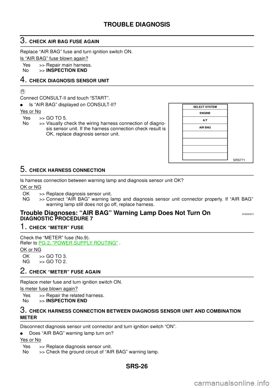
4.CHECK DIAGNOSIS SENSOR UNIT
Connect CONSULT-II and touch “START”.
lIs “AIR BAG” displayed on CONSULT-II?
Ye s o r N o
Yes >>GOTO5.
No >> Visually check the wiring harness connection of diagno-
sis sensor unit. If the harness connection check result is
OK, replace diagnosis sensor unit.
5.CHECK HARNESS CONNECTION
Is harness connection between warning lamp and diagnosis sensor unit OK?
OK or NG
OK >> Replace diagnosis sensor unit.
NG >> Connect “AIR BAG” warning lamp and diagnosis sensor unit connector properly. If “AIR BAG”
warning lamp still does not go off, replace harness.
Trouble Diagnoses: “AIR BAG” Warning Lamp Does Not Turn OnEHS000CV
DIAGNOSTIC PROCEDURE 7
1.CHECK “METER” FUSE
Check the “METER” fuse (No.9).
Refer toPG-2, "
POWER SUPPLY ROUTING".
OK or NG
OK >> GO TO 3.
NG >> GO TO 2.
2.CHECK “METER” FUSE AGAIN
Replace meter fuse and turn ignition switch ON.
Is meter fuse blown again?
Yes >> Repair the related harness.
No >>INSPECTION END
3.CHECK HARNESS CONNECTION BETWEEN DIAGNOSIS SENSOR UNIT AND COMBINATION
METER
Disconnect diagnosis sensor unit connector and turn ignition switch “ON”.
lDoes “AIR BAG” warning lamp turn on?
Ye s o r N o
Yes >> Replace diagnosis sensor unit.
No >> Check the ground circuit of “AIR BAG” warning lamp.
SRS771
Page 2959 of 3066
SIDE AIR BAG (SATELLITE) SENSOR
SRS-37
C
D
E
F
G
I
J
K
L
MA
B
SRS
SIDE AIR BAG (SATELLITE) SENSORPFP:98830
Removal and InstallationEHS000DB
REMOVAL
CAUTION:
lBefore servicing SRS, turn the ignition switch off, disconnect the battery ground cable and wait at
least 3 minutes.
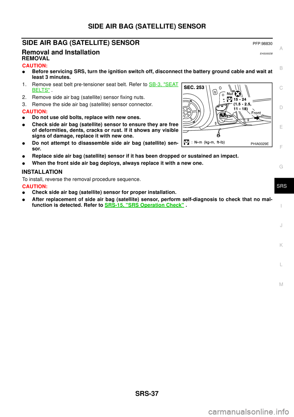
1. Remove seat belt pre-tensioner seat belt. Refer toSB-3, "
SEAT
BELTS".
2. Remove side air bag (satellite) sensor fixing nuts.
3. Remove the side air bag (satellite) sensor connector.
CAUTION:
lDo not use old bolts, replace with new ones.
lCheck side air bag (satellite) sensor to ensure they are free
of deformities, dents, cracks or rust. If it shows any visible
signs of damage, replace it with new one.
lDo not attempt to disassemble side air bag (satellite) sen-
sor.
lReplace side air bag (satellite) sensor if it has been dropped or sustained an impact.
lWhen the front side air bag deploys, always replace it with a new one.
INSTALLATION
To install, reverse the removal procedure sequence.
CAUTION:
lCheck side air bag (satellite) sensor for proper installation.
lAfter replacement of side air bag (satellite) sensor, perform self-diagnosis to check that no mal-
function is detected. Refer toSRS-15, "
SRS Operation Check".
PHIA0029E
Page 2961 of 3066
DIAGNOSIS SENSOR UNIT
SRS-39
C
D
E
F
G
I
J
K
L
MA
B
SRS
DIAGNOSIS SENSOR UNITPFP:28556
Removal and InstallationEHS000DD
REMOVAL
CAUTION:
lBefore servicing SRS, turn the ignition switch off, disconnect the battery ground cable and wait at
least 3 minutes.
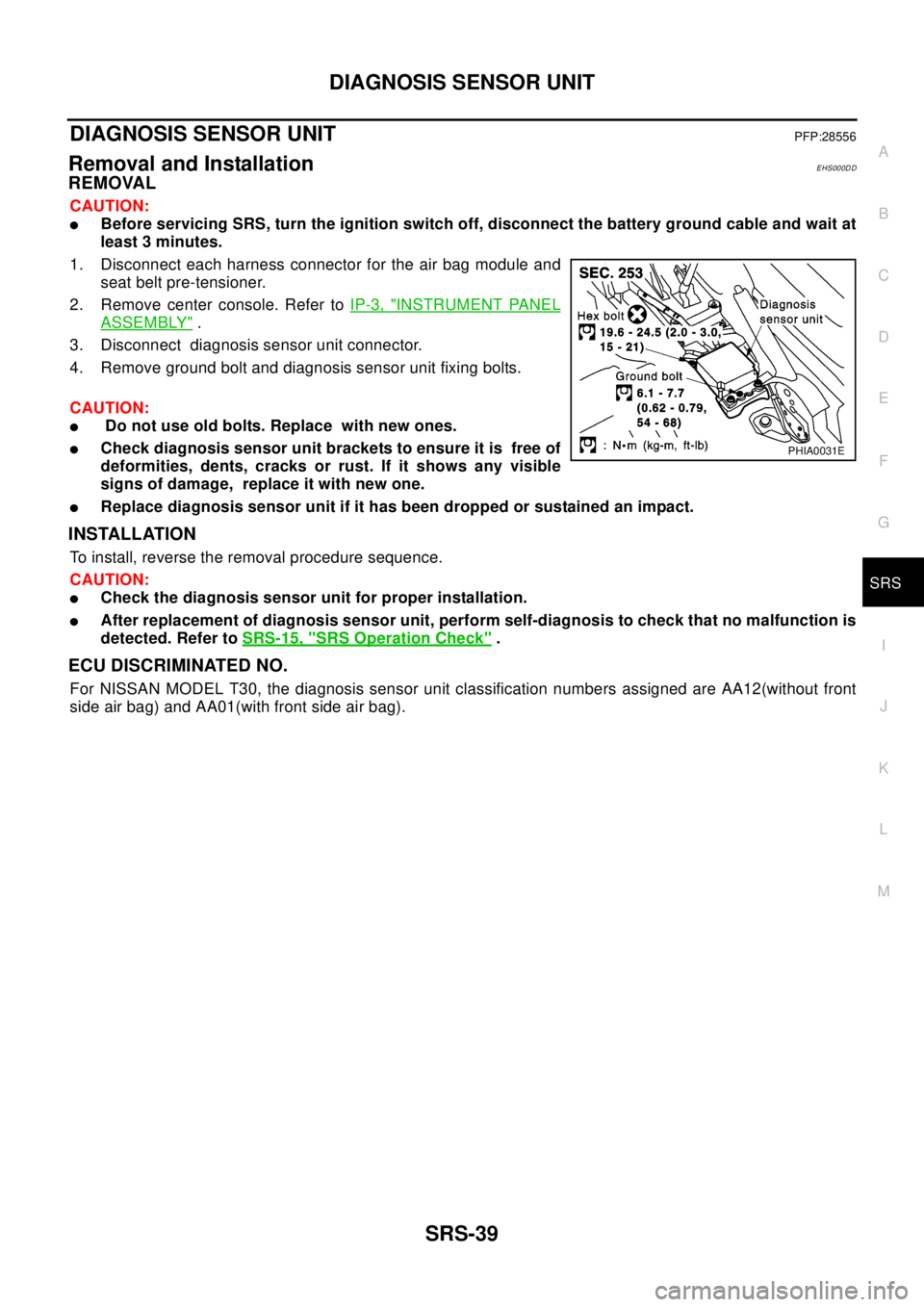
1. Disconnect each harness connector for the air bag module and
seat belt pre-tensioner.
2. Remove center console. Refer toIP-3, "
INSTRUMENT PANEL
ASSEMBLY".
3. Disconnect diagnosis sensor unit connector.
4. Remove ground bolt and diagnosis sensor unit fixing bolts.
CAUTION:
lDo not use old bolts. Replace with new ones.
lCheck diagnosis sensor unit brackets to ensure it is free of
deformities, dents, cracks or rust. If it shows any visible
signs of damage, replace it with new one.
lReplace diagnosis sensor unit if it has been dropped or sustained an impact.
INSTALLATION
To install, reverse the removal procedure sequence.
CAUTION:
lCheck the diagnosis sensor unit for proper installation.
lAfter replacement of diagnosis sensor unit, perform self-diagnosis to check that no malfunction is
detected. Refer toSRS-15, "
SRS Operation Check".
ECU DISCRIMINATED NO.
For NISSAN MODEL T30, the diagnosis sensor unit classification numbers assigned are AA12(without front
side air bag) and AA01(with front side air bag).
PHIA0031E
Page 2968 of 3066
SRS-46
COLLISION DIAGNOSIS
COLLISION DIAGNOSIS
PFP:00015
For Frontal CollisionEHS000DF
To repair the SRS, perform the following steps.
WHEN SRS (EXCEPT THE FRONT SIDE AIR BAG ) IS ACTIVED IN A COLLISION :
1. Replace the diagnosis sensor unit.
2. Remove the air bag modules (except the front side air bag module), bracket and seat belt pre-tensioner
assemblies.
3. Check the SRS components using the table shown below:
–Replace any SRS components showing visible signs of damage (dents, cracks and deformation).
4. Install new air bag modules (except the front side air bag module ) and seat belt pre-tensioner assemblies.
5. Conduct self-diagnosis using CONSULT-II or “AIR BAG” warning lamp. Refer toSRS-15, "
SRS Operation
Check"for details. Ensure entire SRS operation properly.
WHEN SRS IS NOT ACTIVATED IN A COLLISION:
1. Check the SRS components using the table shown below:
–Replace any SRS components showing visible signs of damage (dents, cracks and deformation).
2. Conduct self-diagnosis using CONSULT-II or “AIR BAG” warning lamp. Refer toSRS-15, "
SRS Operation
Check"for details. Ensure entire SRS operation properly.
SRS INSPECTION (FOR FRONTAL COLLISION)
Part SRS is activated SRS is NOT activated
Air bag module
(driver and front pas-
senger air bag mod-
ule)REPLACE
Install with new bolts.1. Remove air bag module. Check harness cover and connectors for damage, termi-
nals for deformities, and harness for binding.
2.
–Install driver air bag module into the steering wheel to check fit and alignment with
the wheel.
–Install passenger air bag module into the instrument panel to check fit with the
instrument panel.
3. No damage found, reinstall with new bolts.
4. If damaged—REPLACE. Install air bag modules with new special bolts
Air bag must be deployed before discarding.
Seat belt pre-ten-
sioner assemblyREPLACE
Install seat belt pre-
tensioner with new
bolts.1. Remove seat belt pre-tensioners.
Check harness cover and connectors for damage, terminals for deformities, and
harness for binding.
2. Check belts for damage and anchors for loose mounting.
3. Check retractor for smooth operation.
4. If no damage is found, reinstall seat belt pre-tensioner assembly.
5. If damaged—REPLACE. Install the seat belt pre-tensioners with new bolts.
Seat belt pre-tensioners must be deployed before discarding.
Diagnosis sensor unit REPLACE
Install with new bolts.1. Check case for dents, cracks or deformities.
2. Check connectors for damage, and terminals for deformities.
3. If no damage is found, reinstall with new bolts and ground bolt.
4. If damaged—REPLACE. Install diagnosis sensor unit with new bolts and ground
bolt.
Steering wheel 1. Visually check steering wheel for deformities.
2. Check harness (built into steering wheel) and connectors for damage, and terminals for deformities.
3. Install air bag module to check fit or alignment with steering wheel.
4. Check steering wheel for excessive free play.
5. If no damage is found, reinstall with bolts.
6. If damaged—REPLACE.
Page 2969 of 3066
COLLISION DIAGNOSIS
SRS-47
C
D
E
F
G
I
J
K
L
MA
B
SRS
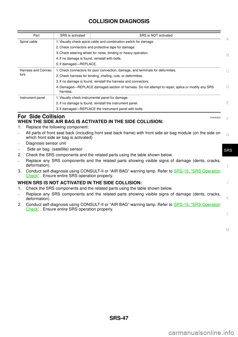
For Side CollisionEHS000DG
WHENTHESIDEAIRBAGISACTIVATEDINTHESIDECOLLISION:
1. Replace the following component:
–All parts of front seat back (including front seat back frame) with front side air bag module (on the side on
which front side air bag is activated)
–Diagnosis sensor unit
–Side air bag (satellite) sensor
2. Check the SRS components and the related parts using the table shown below.
–Replace any SRS components and the related parts showing visible signs of damage (dents, cracks,
deformation).
3. Conduct self-diagnosis using CONSULT-II or “AIR BAG” warning lamp. Refer toSRS-15, "
SRS Operation
Check". Ensure entire SRS operation properly.
WHEN SRS IS NOT ACTIVATED IN THE SIDE COLLISION:
1. Check the SRS components and the related parts using the table shown below.
–Replace any SRS components and the related parts showing visible signs of damage (dents, cracks,
deformation).
2. Conduct self-diagnosis using CONSULT-II or “AIR BAG” warning lamp. Refer toSRS-15, "
SRS Operation
Check". Ensure entire SRS operation properly.
Spiral cable 1. Visually check spiral cable and combination switch for damage.
2. Check connectors and protective tape for damage.
3. Check steering wheel for noise, binding or heavy operation.
4. If no damage is found, reinstall with bolts.
5. If damaged—REPLACE.
Harness and Connec-
tors1. Check connectors for poor connection, damage, and terminals for deformities.
2. Check harness for binding, chafing, cuts, or deformities.
3. If no damage is found, reinstall the harness and connectors.
4. Damaged—REPLACE damaged section of harness. Do not attempt to repair, splice or modify any SRS
harness.
Instrument panel 1. Visually check instrumental panel for damage.
2. If no damage is found, reinstall the instrument panel.
3. If damaged—REPLACE the instrument panel with bolts. Part SRS is activated SRS is NOT activated
Page 2970 of 3066

SRS-48
COLLISION DIAGNOSIS
SRS INSPCTION (FOR SIDE COLLISION)
PartFront side air bag and
side curtain air bag is
activatedFront side air bag and side curtain air bag is NOT activated
Front (LH or RH) side
air bag moduleREPLACE all parts of
seat back with
deployed front side
air bag module.1. Check for visible signs of damage (dents, tears, deformation) of the seat back on
the collision side.
2. If damaged—REPLACE the damaged seat parts with new bolts and remove the
front side air bag module.
3. Check for visible signs of damaged (tears etc.) of the front side air bag module.
4. Check harness and connectors for damage, and terminals for deformities.
5. If no damaged is found, reinstall the front side air bag module with new nuts.
6. If damaged—REPLACE the front side air bag module with new nut.
Air bag must be deployed before disposing of it.
(LH or RH) side air
bag (satellite) sensorREPLACE the side
air bag (satellite)
sensor on the colli-
sion side with new
nuts.
(Repair the center pil-
lar inner, etc. before
installing new one if
damaged.)1. Remove the side air bag (satellite) sensor on the collision side. Check harness
connectors for damage, terminals for deformities, and harness for binding.
2. Check for visible signs of damage (dents, cracks, deformation) of the side air bag
(satellite) sensor.
3. Install the side air bag (satellite) sensor to check fit.
4. If no damage is found, reinstall the side sir bag (satellite) sensor with new nuts.
5. If damaged—REPLACE the side air bag (satellite) sensor with new nuts.
Diagnosis sensor unit REPLACE the diag-
nosis sensor unit with
the new bolts.1. Check case and bracket for dents, cracks or deformities.
2. Check connectors for damage, and terminals for deformities.
3. If no damage is found, reinstall the diagnosis sensor unit with new bolts and
ground bolt.
4. If damaged—REPLACE the diagnosis sensor unit with new bolts and ground bolt.
Seat belt pre-ten-
sioner assembly1. Check if the seat belt can be extended smoothly.
If the seat belt cannot be extended smoothly,
–Check for deformities of the center pillar inner.
–If the center pillar inner has no damage, REPLACE the seat belt pre-tensioner assembly.
2. Remove the seat belt pre-tensioner assembly on the collision side. Check harness cover and connectors
for damage, terminals for deformities, and harness for binding.
3. Check for visible signs of damage (dents, cracks, deformation) of the seat belt pre-tensioner assembly.
4. If no damage is found, reinstall the seat belt pre-tensioner assembly.
5. If damaged—REPLACE the seat belt pre-tensioner assembly with new bolts.
The seat belt pre-tensioner assembly must be deployed before disposing of it.
Seat with front side
air bagREPLACE all parts of
front seat back
(including front seat
back frame)1. Visually check the seat on the collision side.
2. Remove the seat on the collision side and check the following for damage and
deformities.
–Harness, connectors and terminals
–Frame and recliner (for front and rear seat), and also adjuster and slides (for front
seat)
3. If no damage is found, reinstall the seat.
4. If damaged—REPLACE the damaged seat parts with new bolts.
Center pillar inner 1. Check the center pillar inner on the collision side for damage (dents, cracks, deformation).
2. If damaged—REPAIR the center pillar inner.
Trim 1. Check for visible signs of damage (dents, cracks, deformation) of the interior trim on the collision side.
2. If damaged—REPLACE the damaged trim parts.
Page 2971 of 3066
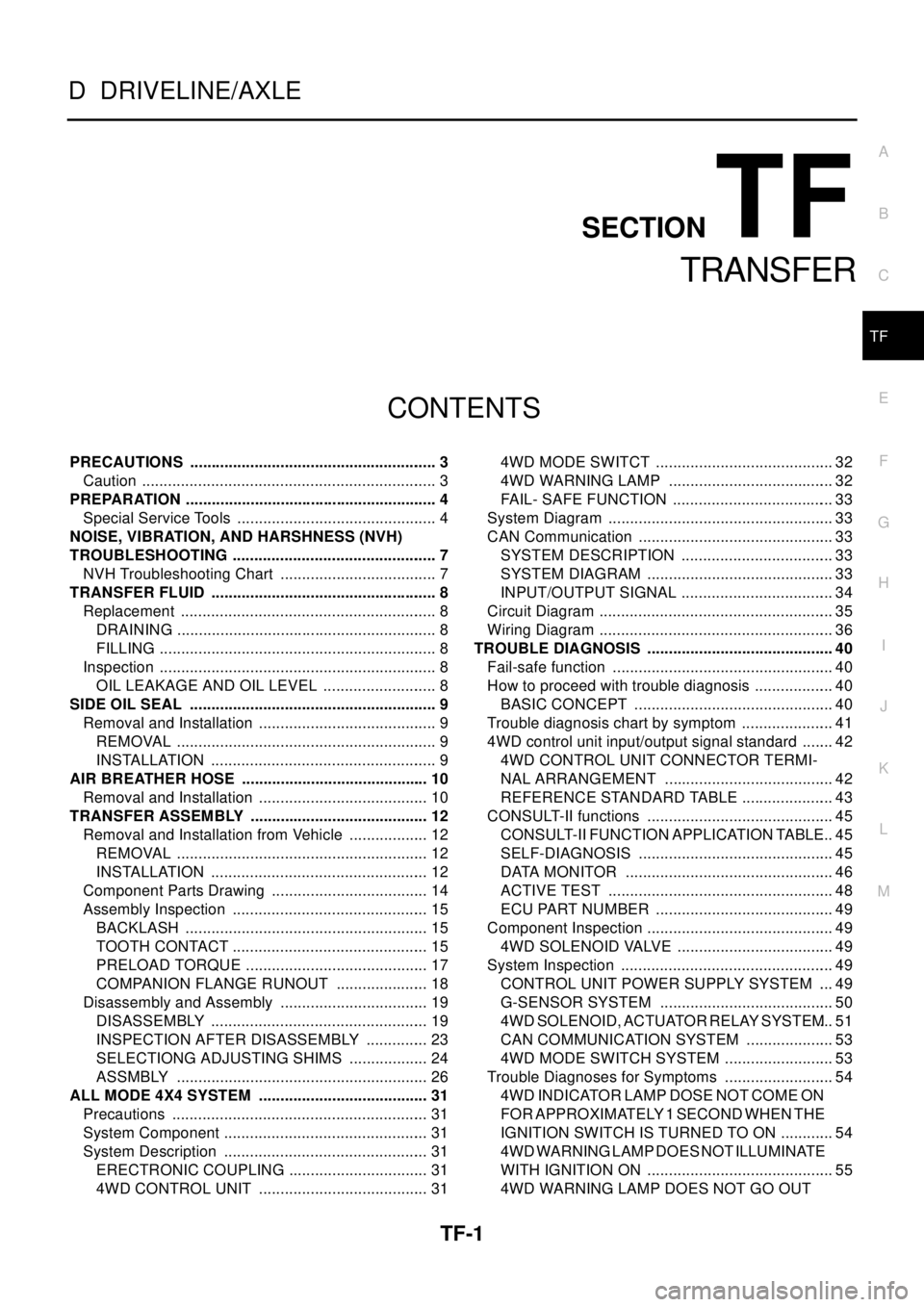
TF-1
TRANSFER
D DRIVELINE/AXLE
CONTENTS
C
E
F
G
H
I
J
K
L
M
SECTION
A
B
TF
TRANSFER
PRECAUTIONS .......................................................... 3
Caution ..................................................................... 3
PREPARATION ........................................................... 4
Special Service Tools ............................................... 4
NOISE, VIBRATION, AND HARSHNESS (NVH)
TROUBLESHOOTING ................................................ 7
NVH Troubleshooting Chart ..................................... 7
TRANSFER FLUID ..................................................... 8
Replacement ............................................................ 8
DRAINING ............................................................. 8
FILLING ................................................................. 8
Inspection ................................................................. 8
OIL LEAKAGE AND OIL LEVEL ........................... 8
SIDE OIL SEAL .......................................................... 9
Removal and Installation .......................................... 9
REMOVAL ............................................................. 9
INSTALLATION ..................................................... 9
AIR BREATHER HOSE ............................................ 10
Removal and Installation ........................................ 10
TRANSFER ASSEMBLY .......................................... 12
Removal and Installation from Vehicle ................... 12
REMOVAL ........................................................... 12
INSTALLATION ................................................... 12
Component Parts Drawing ..................................... 14
Assembly Inspection .............................................. 15
BACKLASH ......................................................... 15
TOOTH CONTACT .............................................. 15
PRELOAD TORQUE ........................................... 17
COMPANION FLANGE RUNOUT ...................... 18
Disassembly and Assembly ................................... 19
DISASSEMBLY ................................................... 19
INSPECTION AFTER DISASSEMBLY ............... 23
SELECTIONG ADJUSTING SHIMS ................... 24
ASSMBLY ........................................................... 26
ALL MODE 4X4 SYSTEM ........................................ 31
Precautions ............................................................ 31
System Component ................................................ 31
System Description ................................................ 31
ERECTRONIC COUPLING ................................. 31
4WD CONTROL UNIT ........................................ 314WD MODE SWITCT .......................................... 32
4WD WARNING LAMP ....................................... 32
FAIL- SAFE FUNCTION ...................................... 33
System Diagram ..................................................... 33
CAN Communication .............................................. 33
SYSTEM DESCRIPTION .................................... 33
SYSTEM DIAGRAM ............................................ 33
INPUT/OUTPUT SIGNAL .................................... 34
Circuit Diagram ....................................................... 35
Wiring Diagram ....................................................... 36
TROUBLE DIAGNOSIS ............................................ 40
Fail-safe function .................................................... 40
How to proceed with trouble diagnosis ................... 40
BASIC CONCEPT ............................................... 40
Trouble diagnosis chart by symptom ...................... 41
4WD control unit input/output signal standard ........ 42
4WD CONTROL UNIT CONNECTOR TERMI-
NAL ARRANGEMENT ........................................ 42
REFERENCE STANDARD TABLE ...................... 43
CONSULT-II functions ............................................ 45
CONSULT-II FUNCTION APPLICATION TABLE... 45
SELF-DIAGNOSIS .............................................. 45
DATA MONITOR ................................................. 46
ACTIVE TEST ..................................................... 48
ECU PART NUMBER .......................................... 49
Component Inspection ............................................ 49
4WD SOLENOID VALVE ..................................... 49
System Inspection .................................................. 49
CONTROL UNIT POWER SUPPLY SYSTEM .... 49
G-SENSOR SYSTEM ......................................... 50
4WD SOLENOID, ACTUATOR RELAY SYSTEM... 51
CAN COMMUNICATION SYSTEM ..................... 53
4WD MODE SWITCH SYSTEM .......................... 53
Trouble Diagnoses for Symptoms .......................... 54
4WD INDICATOR LAMP DOSE NOT COME ON
FORAPPROXIMATELY1SECONDWHENTHE
IGNITION SWITCH IS TURNED TO ON ............. 54
4WD WARNING LAMP DOES NOT ILLUMINATE
WITH IGNITION ON ............................................ 55
4WD WARNING LAMP DOES NOT GO OUT
Page 3001 of 3066
ALL MODE 4X4 SYSTEM
TF-31
C
E
F
G
H
I
J
K
L
MA
B
TF
ALL MODE 4X4 SYSTEMPFP:47850
PrecautionsEDS000IV
lThis section describes ESP/TCS/ABS model.
lRefer to the BRC section for model without ESP/TCS/ABS.Refer toBRC-6, "ALL MODE 4X4 SYSTEM"
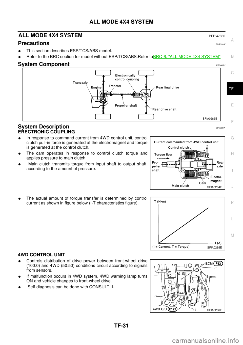
System ComponentEDS000IJ
System DescriptionEDS000IK
ERECTRONIC COUPLING
lIn response to command current from 4WD control unit, control
clutch pull-in force is generated at the electromagnet and torque
is generated at the control clutch.
lThe cam operates in response to control clutch torque and
applies pressure to main clutch.
lMain clutch transmits torque from input shaft to output shaft,
according to the amount of pressure.
lThe actual amount of torque transfer is determined by control
current as shown in figure below (I-T characteristics figure).
4WD CONTROL UNIT
lControls distribution of drive power between front-wheel drive
(100:0) and 4WD (50:50) conditions circuit according to signals
from sensors.
lIf malfunction occurs in 4WD system, 4WD warning lamp turns
ON and vehicle changes to front-wheel drive.
lSelf-diagnosis can be done with CONSULT-II.
SFIA0283E
SFIA0284E
SFIA0285E
SFIA0286E