2003 NISSAN X-TRAIL sensor
[x] Cancel search: sensorPage 2762 of 3066

PS-2
PRECAUTIONS
PRECAUTIONS
PFP:00001
Precautions for models with SRS air bag and pre-tensioner seat beltEGS00048
WAR NIN G:
lBefore removing and installing components and harnesses of SRS air bag and seat belt pre-ten-
sioner system, turn ignition switch OFF, disconnect battery ground cable, and wait at least 3 min-
utes. (This discharges electricity held in the air bag sensor unit's additional power circuit.)
lDo not use pneumatic or electric tools to remove and install the components.
lDo not solder SRS air bag and seat belt pre-tensioner system harnesses when making repairs.
Make sure harness is not pinched and there is no contact with other components.
lWhen checking the SRS air bag and the seat belt pre-tensioner circuit or the components of each
system, do not use an electric tester such as a circuit tester. (This is to prevent accidental trigger-
ing caused by the weak electric current of a tester.)
lNever insert foreign material (such as a screwdriver) in the air bag module and pre-tensioner seat
belt connectors. (The units may be actuated by mistake by static electricity.)
lSeat belt pre-tensioner and SRS air bag harnesses can be distinguished from other harnesses by
their yellow connectors.
lWhen servicing, refer to “SB Seat Belt” and “SRS Air Bag” for safety.
CautionEGS00049
lAlways follow the warnings and the cautions below in disassembly procedures:
–Work in a clean, dust-free place. No dust proof device is necessary.
–Clean outside of unit before disassembly.
–Clean parts to be disassembled. Be careful not to allow any dirt or other foreign materials to enter or con-
tact with parts.
–Assemble disassembled parts properly, following order shown in manual. If work has been suspended in
the middle of assembly, place a clean cover over parts. This will prevent them from being contaminated.
–Use paper towels when removing dirt and other foreign materials. Cloth shop towels can leave lint on
cleaned parts that might affect operation of parts.
–Clean disassembled parts (except rubber parts) with kerosene. Drain oil by blowing with air or absorbing
with shop papers.
–Before assembling, apply Nissan power steering fluid to O-rings and seals.
–Replace gaskets and O-rings with new ones. Be careful not to damage any O-rings, oil seals, and gaskets
during assembly.
lIf following part is scratched after disassembly of steering pump, replace applicable part: case, rear body,
side plate, pulley, rotor, vane, or flow control valve
lMark source of fluid leak with a white marker for identification.
lSeals and copper washers must not be reused.
Page 2803 of 3066
WHEEL HUB (4WD)
RAX-7
C
E
F
G
H
I
J
K
L
MA
B
RAX
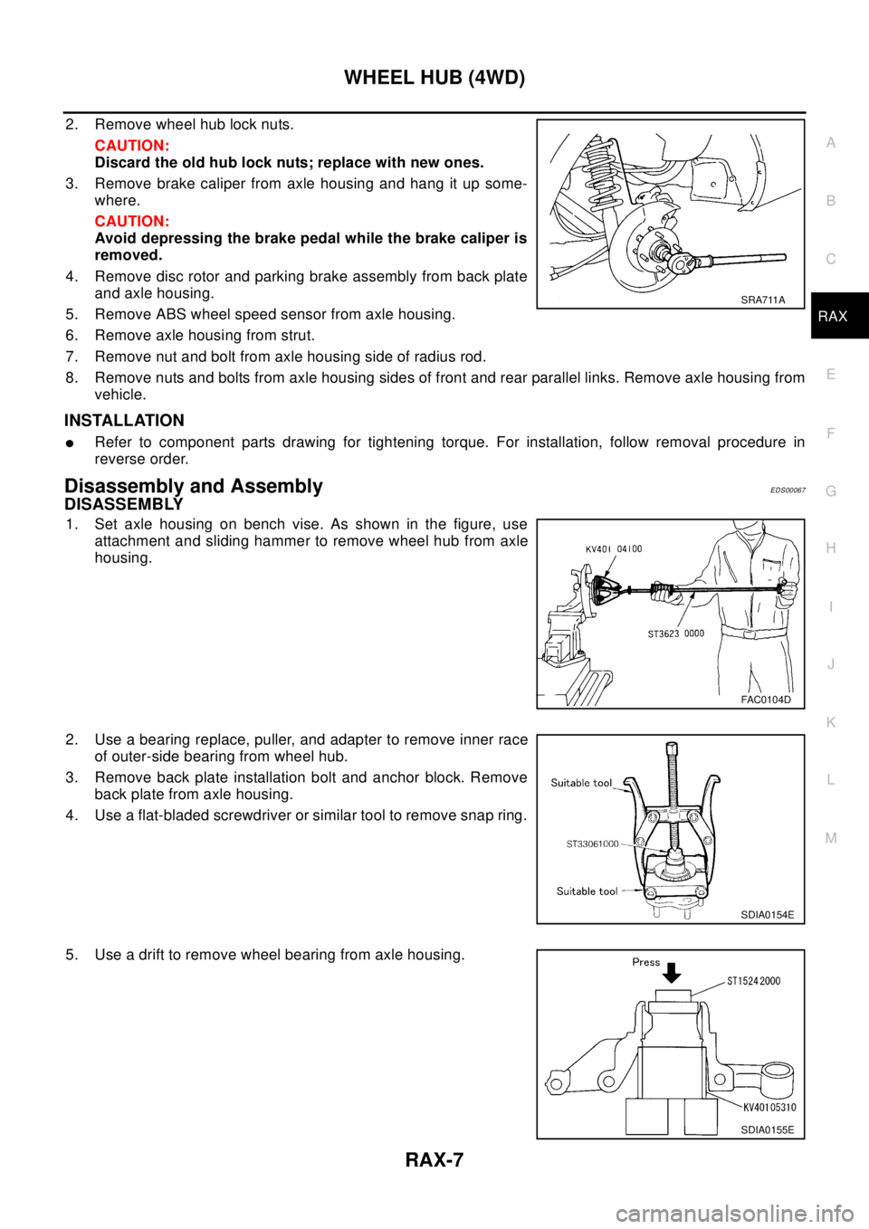
2. Remove wheel hub lock nuts.
CAUTION:
Discard the old hub lock nuts; replace with new ones.
3. Remove brake caliper from axle housing and hang it up some-
where.
CAUTION:
Avoid depressing the brake pedal while the brake caliper is
removed.
4. Remove disc rotor and parking brake assembly from back plate
andaxlehousing.
5. Remove ABS wheel speed sensor from axle housing.
6. Remove axle housing from strut.
7. Remove nut and bolt from axle housing side of radius rod.
8. Remove nuts and bolts from axle housing sides of front and rear parallel links. Remove axle housing from
vehicle.
INSTALLATION
lRefer to component parts drawing for tightening torque. For installation, follow removal procedure in
reverse order.
Disassembly and AssemblyEDS00067
DISASSEMBLY
1. Set axle housing on bench vise. As shown in the figure, use
attachment and sliding hammer to remove wheel hub from axle
housing.
2. Use a bearing replace, puller, and adapter to remove inner race
of outer-side bearing from wheel hub.
3. Remove back plate installation bolt and anchor block. Remove
back plate from axle housing.
4. Use a flat-bladed screwdriver or similar tool to remove snap ring.
5. Use a drift to remove wheel bearing from axle housing.
SRA711A
FAC0104D
SDIA0154E
SDIA0155E
Page 2806 of 3066
RAX-10
REAR DRIVE SHAFT
Disassembly and Assembly
EDS000FM
DISASSEMBLY
Final Drive Side
1. Remove boot bands.
2. Fix shaft to bench vise.
CAUTION:
When fixing shaft to bench vise, be sure to protect it with a copper or aluminum sheet.
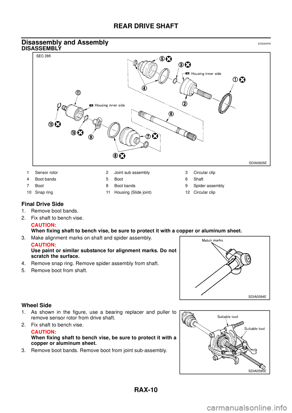
3. Make alignment marks on shaft and spider assembly.
CAUTION:
Use paint or similar substance for alignment marks. Do not
scratch the surface.
4. Remove snap ring. Remove spider assembly from shaft.
5. Remove boot from shaft.
Wheel Side
1. As shown in the figure, use a bearing replacer and puller to
remove sensor rotor from drive shaft.
2. Fix shaft to bench vise.
CAUTION:
When fixing shaft to bench vise, be sure to protect it with a
copper or aluminum sheet.
3. Remove boot bands. Remove boot from joint sub-assembly.
SDIA0605E
1 Sensor rotor 2 Joint sub assembly 3 Circular clip
4 Boot bands 5 Boot 6 Shaft
7 Boot 8 Boot bands 9 Spider assembly
10 Snap ring 11 Housing (Slide joint) 12 Circular clip
SDIA0594E
SDIA0595E
Page 2809 of 3066
REAR DRIVE SHAFT
RAX-13
C
E
F
G
H
I
J
K
L
MA
B
RAX
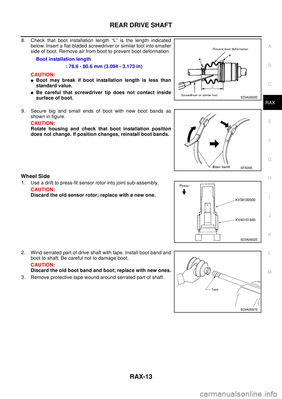
8. Check that boot installation length “L” is the length indicated
below. Insert a flat-bladed screwdriver or similar tool into smaller
side of boot. Remove air from boot to prevent boot deformation.
CAUTION:
lBoot may break if boot installation length is less than
standard value.
lBe careful that screwdriver tip does not contact inside
surface of boot.
9. Secure big and small ends of boot with new boot bands as
shown in figure.
CAUTION:
Rotate housing and check that boot installation position
does not change. If position changes, reinstall boot bands.
Wheel Side
1. Use a drift to press-fit sensor rotor into joint sub-assembly.
CAUTION:
Discard the old sensor rotor; replace with a new one.
2. Wind serrated part of drive shaft with tape. Install boot band and
boot to shaft. Be careful not to damage boot.
CAUTION:
Discard the old boot band and boot; replace with new ones.
3. Remove protective tape wound around serrated part of shaft.Boot installation length
: 78.6 - 80.6 mm (3.094 - 3.173 in)
SDIA0600E
SFA395
SDIA0602E
SDIA0597E
Page 2833 of 3066
REAR FINAL DRIVE ASSEMBLY
RFD-11
C
E
F
G
H
I
J
K
L
MA
B
RFD
REAR FINAL DRIVE ASSEMBLYPFP:38300
Removal and InstallationEDS000DG
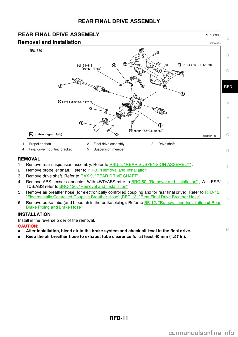
REMOVAL
1. Remove rear suspension assembly. Refer toRSU-5, "REAR SUSPENSION ASSEMBLY".
2. Remove propeller shaft. Refer toPR-3, "
Removal and Installation".
3. Remove drive shaft. Refer toRAX-9, "
REAR DRIVE SHAFT".
4. Remove ABS sensor connector. With 4WD/ABS refer toBRC-50, "
Removal and Installation", With ESP/
TCS/ABS refer toBRC-120, "
Removal and Installation"
5. Remove air breather hose (for electronically controlled coupling and for rear final drive). Refer toRFD-12,
"Electronically Controlled Coupling Breather Hose",RFD-13, "Rear Final Drive Breather Hose".
6. Remove brake tube (and bleed air in the brake piping). Refer toBR-12, "
Removal and Installation of Rear
Brake Piping and Brake Hose".
INSTALLATION
Install in the reverse order of the removal.
CAUTION:
lAfter installation, bleed air in the brake system and check oil level in the final drive.
lKeep the air breather hose to exhaust tube clearance for at least 40 mm (1.57 in).
SDIA0108E
1 Propeller shaft 2 Final drive assembly 3 Drive shaft
4 Final drive mounting bracket 5 Suspension member
Page 2862 of 3066
RSU-10
FRONT PARALLEL LINK
FRONT PARALLEL LINK
PFP:55120
Removal and InstallationEES0007J
REMOVAL
1. Remove tires, Raise vehicle.
2. Remove ABS wheel speed sensor wire (With ABS models).
3. Remove front parallel link mounting bolts and nuts. Remove front parallel link from vehicle.
INSPECTION AFTER REMOVAL
lReplace front parallel link assembly if it is in following condition: deformed, cracked, or damaged, or if the
bushing was damaged.
INSTALLATION
lRefer toRSU-5, "Components"for tightening torque and reverse the removal procedure for installation.
Page 2865 of 3066
REAR SUSPENSION MEMBER
RSU-13
C
D
F
G
H
I
J
K
L
MA
B
RSU
REAR SUSPENSION MEMBERPFP:55501
Removal and InstallationEES0007M
REMOVAL
1. Remove tires. Raise vehicle.
2. Remove cotter pin.Remove wheel hub lock nut by using a wheel hub lock nut wrench.
3. Remove ABS wheel speed sensor and wiring (With ABS models).
4. Remove brake caliper and brake hose lock plate, and hang them aside.
5. Remove mounting bolts and nuts on lower portion of strut.
6. Remove axle-side mounting bolts of parallel link and remove rear drive shaft from axle housing.
7. Remove suspension member-side mounting bolt of parallel link and remove parallel link from suspension
member.
8. Remove mounting bolts and nuts on lower portion of strut.
CAUTION:
After removing drive shaft, position axle housing onto strut.
9. Remove propeller shaft.
10. Remove rear exhaust tube.
11. Remove electronically controlled coupling connector and air breather hose from final drive.
12. Set a transmission jack under rear final drive.
13. Remove front and rear mounting bolts from rear final drive.
14. Remove rear final drive from suspension member.
15. Place transmission jack onto rear suspension member. Remove rear suspension member mounting bolts.
Lower transmission jack slowly to remove rear suspension member from vehicle.
INSTALLATION
lRefer toRSU-5, "Components"for tightening torque. Install in the reverse order of removal.
lAfter installation, perform final tightening of each part under unladen conditions with tires on ground.
Check wheel alignment.RSU-6, "
Wheel Alignment".
Page 2923 of 3066
SRS-1
SUPPLEMENTAL RESTRAINT SYSTEM (SRS)
H RESTRAINTS
CONTENTS
C
D
E
F
G
I
J
K
L
M
SECTION
A
B
SRS
SUPPLEMENTAL RESTRAINT SYSTEM (SRS)
PRECAUTIONS .......................................................... 3
Supplemental Restraint System (SRS) “AIR BAG”
and “SEAT BELT PRE-TENSIONER” ...................... 3
Precautions for SRS “AIR BAG” and “SEAT BELT
PRE-TENSIONER” Service ..................................... 3
Trouble Diagnosis Precaution .................................. 3
PREPARATION ........................................................... 4
Special Service Tool ................................................. 4
Commercial Service Tool ......................................... 4
SUPPLEMENTAL RESTRAINT SYSTEM (SRS) ....... 5
SRS Configuration ................................................... 5
Front Seat Belt Pre-tensioner with Load Limiter ...... 5
Front Side Air Bag .................................................... 5
TROUBLE DIAGNOSIS .............................................. 7
Trouble Diagnoses-Introduction ............................... 7
DIAGNOSIS FUNCTION ....................................... 7
HOW TO PERFORM TROUBLE DIAGNOSES
FOR QUICK AND ACCURATE REPAIR ............... 7
WORK FLOW ........................................................ 7
SRS Components Parts Location ............................. 9
Wiring Diagram — SRS — /LHD models ............... 10
Wiring Diagram-SRS-/RHD models ....................... 12
CONSULT-II FUNCTION ........................................ 14
DIAGNOSIS MODE FOR CONSULT-II ............... 14
HOW TO CHANGE SELF-DIAGNOSIS MODE
WITH CONSULT-II .............................................. 14
HOW TO ERASE SELF-DIAGNOSIS RESULTS... 14
SELF-DIAGNOSIS FUNCTION (WITHOUT CON-
SULT-II) .................................................................. 15
HOW TO CHANGE SELF-DIAGNOSIS MODE... 15
HOW TO ERASE SELF-DIAGNOSIS RESULTS... 15
SRS Operation Check ............................................ 15
DIAGNOSTIC PROCEDURE 1 ........................... 15
Trouble Diagnoses with CONSULT–II .................... 17
DIAGNOSTIC PROCEDURE 2 ........................... 17
DIAGNOSTIC PROCEDURE 3 ........................... 20
DIAGNOSTIC PROCEDURE 4 ........................... 20
Trouble Diagnoses Without CONSULT-II ............... 22
DIAGNOSTIC PROCEDURE 5 ........................... 22
WARNING LAMP FLASH CODE CHART ........... 23Trouble Diagnoses: “AIR BAG” Warning Lamp Does
Not Turn Off ............................................................ 25
DIAGNOSTIC PROCEDURE 6 ........................... 25
Trouble Diagnoses: “AIR BAG” Warning Lamp Does
Not Turn On ............................................................ 26
DIAGNOSTIC PROCEDURE 7 ........................... 26
DRIVER AIR BAG MODULE .................................... 27
Removal and Installation/With 4-Spoke Steering
Wheel ..................................................................... 27
REMOVAL ........................................................... 27
INSTALLATION ................................................... 28
Removal and Installation/With 3-Spoke Steering
Wheel ..................................................................... 29
REMOVAL ........................................................... 29
INSTALLATION ................................................... 30
SPIRAL CABLE ........................................................ 31
Removal and Installation ........................................ 31
REMOVAL ........................................................... 31
INSTALLATION ................................................... 32
Components Inspection .......................................... 32
FRONT PASSENGER AIR BAG MODULE .............. 33
Removal and Installation ........................................ 33
REMOVAL ........................................................... 33
INSTALLATION ................................................... 33
FRONT SIDE AIR BAG MODULE ............................ 35
Removal and Installation ........................................ 35
REMOVAL ........................................................... 35
INSTALLATION ................................................... 36
SIDE AIR BAG (SATELLITE) SENSOR ................... 37
Removal and Installation ........................................ 37
REMOVAL ........................................................... 37
INSTALLATION ................................................... 37
FRONT SEAT BELT PRE-TENSIONER ................... 38
Removal and Installation ........................................ 38
DIAGNOSIS SENSOR UNIT ..................................... 39
Removal and Installation ........................................ 39
REMOVAL ........................................................... 39
INSTALLATION ................................................... 39
ECU DISCRIMINATED NO. ................................ 39
DISPOSAL OF AIR BAG MODULE AND SEAT BELT