Page 3143 of 3502

POWER STEERING OIL PUMP
PS-29
C
D
E
F
H
I
J
K
L
MA
B
PS
POWER STEERING OIL PUMPPFP:49110
On-Vehicle Inspection and ServiceBGS0003Y
CHECKING RELIEF OIL PRESSURE
CAUTION:
Make sure that belt tension is normal before starting the following procedure.
1. Connect the hydraulic pressure gauge [SST] between oil pump
discharge connector and high-pressure hose. Bleed air from the
hydraulic circuit while opening valve fully. Refer to PS-7, "
Air
Bleeding Hydraulic System" .
2. Start engine. Run engine until oil temperature reaches 50 to
80°C (122 to 176°F).
CAUTION:
�Leave the valve of the hydraulic pressure gauge [SST]
fully open while starting and running engine. If engine is
started with the valve closed, the hydraulic pressure in
oil pump goes up to the relief pressure along with
unusual increase of oil temperature.
�Be sure to keep hose clear of belts and other parts when engine is started.
3. Fully close the hydraulic pressure gauge [SST] valve with
engine at idle and measure the relief oil pressure.
CAUTION:
Never keep valve closed for 10 seconds or longer.
4. Open the valve slowly after measuring. Repair oil pump if the
relief oil pressure is outside the standard. Refer to PS-31, "
Dis-
assembly and Assembly (Except for QR20DE Models)" , PS-35,
"Disassembly and Assembly (QR20DE Models)" .
5. After inspection, disconnect the hydraulic pressure gauge [SST]
from hydraulic circuit, then add fluid and bleed air. Refer to PS-
7, "Air Bleeding Hydraulic System" .
Relief oil pressure
Except for QR20DE models8,000 - 8,800 kPa
(80 – 88 bar, 81.6 – 89.8 kg/cm
2 , 1,160 – 1,276 psi)
QR20DE models9,000 – 9,800 kPa
(90 – 98 bar, 91.8 – 100 kg/cm
2 , 1,305 – 1,421 psi)
SGIA0364E
SGIA0726E
Page 3144 of 3502

PS-30
POWER STEERING OIL PUMP
Removal and InstallationBGS0003Z
REMOVAL
1. Drain power steering fluid from reservoir tank.
2. Remove tyres from vehicle.
3. Remove side splash guard.
4. Remove heat insulator from vehicle. (Except for QR20DE mod-
els).
5. Loosen drive belt. Refer to EM-14, "
DRIVE BELTS" (QR20DE
models), EM-128, "
DRIVE BELTS" (Except for QR20DE mod-
els).
6. Remove drive belt from oil pump pulley.
7. Disconnect the pressure sensor electrical connector.
8. Remove piping of high pressure and low pressure (drain fluid
from their pipings). Refer to PS-39, "
HYDRAULIC LINE" .
9. Remove power steering oil pump mounting bolts, and then
remove power steering oil pump. Refer to PS-39, "
HYDRAULIC
LINE" .
INSTALLATION
�Installation is the reverse order of removal. For tightening torque, refer to PS-39, "HYDRAULIC LINE" .
�Perform the following procedure after installing.
–Adjust belt tension (Except for QR20DE models). Refer to EM-128, "DRIVE BELTS" .
–About the installation of QR20DE drive belt, refer to EM-14, "DRIVE BELTS" .
–Bleed air. Refer to PS-7, "Air Bleeding Hydraulic System" .
SGIA0502E
Page 3145 of 3502
BGS00040
COMPONENTS
INSPECTION BEFORE DISASSEMBLY
Disassemble oil pump only when the follow")
POWER STEERING OIL PUMP
PS-31
C
D
E
F
H
I
J
K
L
MA
B
PS
Disassembly and Assembly (Except for QR20DE Models)BGS00040
COMPONENTS
INSPECTION BEFORE DISASSEMBLY
Disassemble oil pump only when the following malfunctions occur.
�If oil leakage is found on oil pump.
�Oil pump pulley is damaged or deformed.
�Performance of oil pump is low.
DISASSEMBLY
NOTE:
Secure oil pump in a vise if necessary.
CAUTION:
Use copper plates when securing in a vise.
1. Remove rear cover mounting bolts, and then remove rear cover from body assembly.
2. Remove gasket from body assembly.
3. Remove dowel pin, cartridge and side plate from body assembly.
4. Remove pulley mounting nut and washer, and then remove pulley from drive shaft assembly.
5. Remove bracket mounting bolts, and then remove bracket from body assembly.
1. Copper washer 2. Joint 3. Flow control valve
4. Spring 5. Suction pipe 6. O-ring
7. Rear cover 8. Gasket 9. Dowel pin
10. Cartridge 11. Cam ring 12. Rotor
13. Vane 14. Side plate 15. O-ring
16. Body assembly 17. Oil seal 18. Drive shaft
19. Snap ring 20. Pulley 21. Bracket
Refer to GI-10, "
Components" , and the followings for the symbols in the figure.
: Apply power steering fluid.
: Apply multi-purpose grease.
SGIA1618E
Page 3146 of 3502

PS-32
POWER STEERING OIL PUMP
6. Remove snap ring from drive shaft and press out it.
CAUTION:
When removing snap ring, be careful not to damage drive
shaft.
7. Remove oil seal from body assembly using flat-bladed screw-
driver.
8. Remove O-ring from body assembly.
9. Remove mounting bolt, and then remove joint and copper
washer, then pull out flow control valve and spring from body
assembly.
10. Remove mounting bolts of suction pipe, and then remove suc-
tion pipe from body assembly.
11. Remove O-ring from body assembly.
INSPECTION AFTER DISASSEMBLY
Body Assembly and Rear Cover Inspection
Check body assembly and rear cover for internal damage. Replace rear cover if it is damaged. Replace oil
pump assembly if body assembly is damaged.
Cartridge Assembly Inspection
Check cam ring, rotor and vane for damage. Replace cartridge assembly if there are.
Side Plate Inspection
Check side plate for damage. Replace side plate if there are.
Flow Control Valve Inspection
Check flow control valve and spring for damage. Replace if there are.
SST010B
SST034A
SGIA0524E
Page 3147 of 3502

POWER STEERING OIL PUMP
PS-33
C
D
E
F
H
I
J
K
L
MA
B
PS
ASSEMBLY
NOTE:
Secure oil pump in a vise if necessary.
CAUTION:
Use copper plates when securing in a vise.
1. Apply recommended grease to oil seal lips (1). Apply recom-
mended fluid to around oil seal, and then install oil seal to body
assembly.
2. Apply recommended fluid to drive shaft, and press drive shaft
into body assembly, then install snap ring.
3. Apply recommended fluid to O-ring, and then install O-ring into
body assembly.
4. Install side plate to body assembly.
5. Install dowel pin (3) into dowel pin hole (A), and then install cam
ring (2) pointing it's D
1 side toward the body assembly (1) side
as shown in the figure.
�When installing cam ring, turn carved face with a letter E (B)
of it to rear cover.
CAUTION:
Do not confuse the assembling direction of cam ring. If
cam ring is installed facing the incorrect direction, it may
cause oil pump operation malfunction.
6. Install rotor to body assembly.
SGIA1150E
SGIA0422E
SGIA1166E
Page 3148 of 3502
PS-34
POWER STEERING OIL PUMP
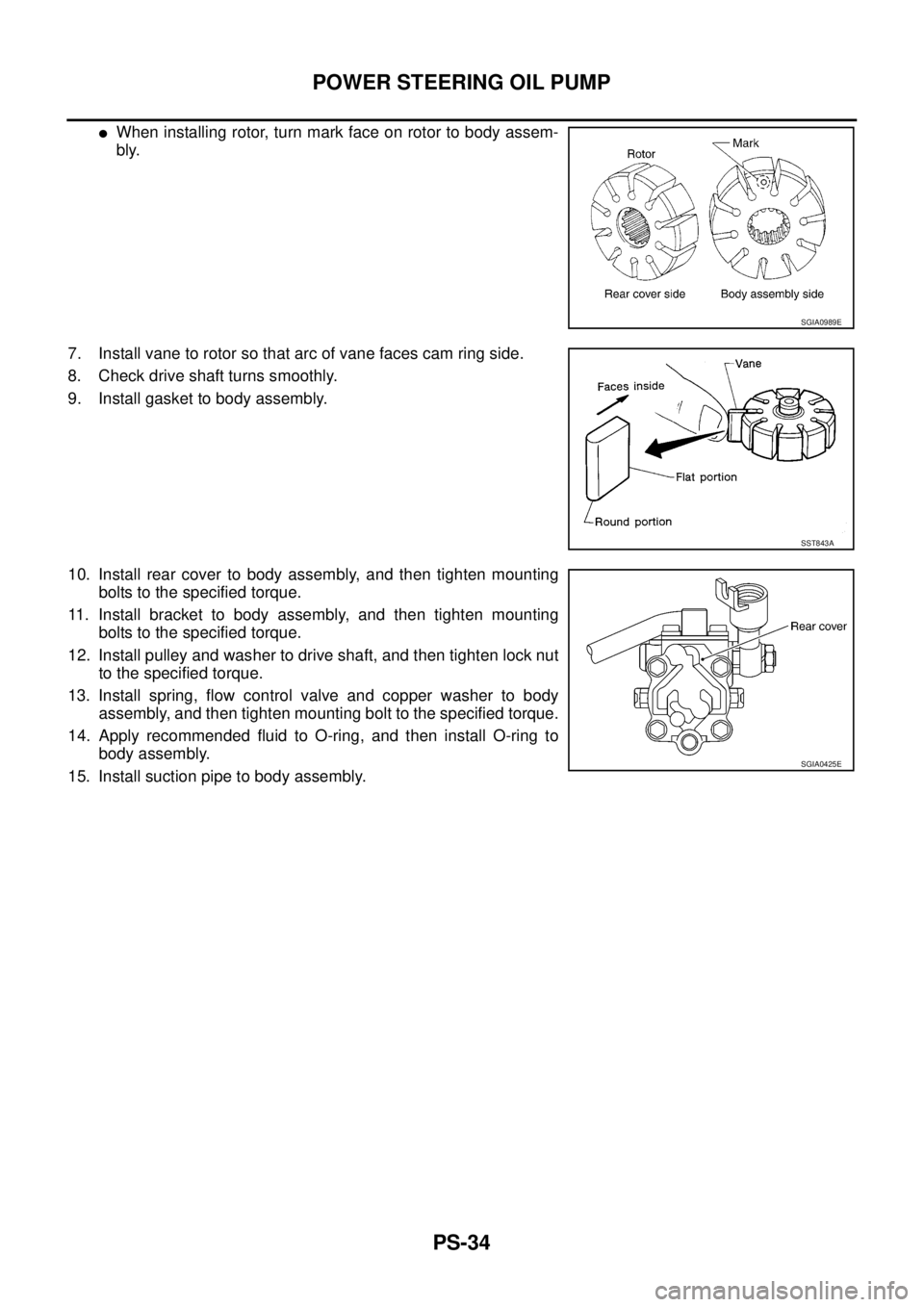
�When installing rotor, turn mark face on rotor to body assem-
bly.
7. Install vane to rotor so that arc of vane faces cam ring side.
8. Check drive shaft turns smoothly.
9. Install gasket to body assembly.
10. Install rear cover to body assembly, and then tighten mounting
bolts to the specified torque.
11. Install bracket to body assembly, and then tighten mounting
bolts to the specified torque.
12. Install pulley and washer to drive shaft, and then tighten lock nut
to the specified torque.
13. Install spring, flow control valve and copper washer to body
assembly, and then tighten mounting bolt to the specified torque.
14. Apply recommended fluid to O-ring, and then install O-ring to
body assembly.
15. Install suction pipe to body assembly.
SGIA0989E
SST843A
SGIA0425E
Page 3149 of 3502
BGS0004D
COMPONENTS
INSPECTION BEFORE DISASSEMBLY
Disassemble oil pump only when the following malfunc")
POWER STEERING OIL PUMP
PS-35
C
D
E
F
H
I
J
K
L
MA
B
PS
Disassembly and Assembly (QR20DE Models)BGS0004D
COMPONENTS
INSPECTION BEFORE DISASSEMBLY
Disassemble oil pump only when the following malfunctions occur.
�If oil leakage is found on oil pump.
�Oil pump pulley is damaged or deformed.
�Performance of oil pump is low.
DISASSEMBLY
NOTE:
Secure oil pump in a vise if necessary.
CAUTION:
Use copper plates when securing in a vise.
1. Remove rear bracket mounting bolts, and then remove rear bracket from rear cover.
2. Remove front bracket mounting bolts, and then remove front bracket from body assembly.
3. Remove rear cover mounting bolts, and then remove rear cover from body assembly.
4. Remove rear side plate from cartridge, and then remove Teflon ring and O-ring from rear side plate.
1. Rear bracket 2. Rear cover 3. Teflon ring
4. O-ring 5. Rear side plate 6. Rotor snap ring
7. Vane 8. Rotor 9. Cam ring
10. Cartridge 11. Front side plate 12. O-ring
13. Dowel pin 14. Flow control valve A 15. Flow control valve spring
16. Flow control valve B assembly 17. Body assembly 18. O-ring
19. Suction pipe 20. Oil seal 21. Front bracket
22. Pulley
Refer to GI-10, "
Components" , and the followings for the symbols in the figure.
: Apply power steering fluid.
: Apply multi-purpose grease.
SGIA1619E
Page 3150 of 3502

PS-36
POWER STEERING OIL PUMP
5. Remove rotor snap ring using a snap ring plier, and remove pul-
ley from body assembly.
CAUTION:
Remove pulley so as not to be damaged when removing
rotor snap ring.
6. Remove cartridge, front side plate, flow control valve A, flow
control valve spring, flow control valve B assembly from body
assembly.
CAUTION:
Do not drop and damage flow control valve A and flow con-
trol valve B assembly when removing.
7. Remove oil seal from body assembly.
8. Remove mounting bolts of suction pipe, and then remove suc-
tion pipe from body assembly.
9. Remove O-ring from body assembly.
INSPECTION AFTER DISASSEMBLY
Body Assembly and Rear Cover Inspection
Check body assembly and rear cover for internal damage. Replace rear cover if it is damaged. Replace oil
pump assembly if body assembly is damaged.
Cartridge Assembly Inspection
Check cam ring, rotor and vane for damage. Replace cartridge assembly if necessary.
Side Plate Inspection
Check side plate (front and rear) for damage. Side plate (front and rear) must be replaced as a set if they are
damaged.
Flow Control Valve Inspection
Check flow control valve A, flow control valve spring and flow control valve B assembly for damage. Replace if
there are.
SGIA0059E
SGIA0526E