Page 3135 of 3502

POWER STEERING GEAR AND LINKAGE
PS-21
C
D
E
F
H
I
J
K
L
MA
B
PS
DISASSEMBLY
1. Remove cylinder tubes from gear housing assembly.
2. Remove rear cover cap from pinion assembly.
3. Using a rear cover wrench [SST: KV489Q0030] (A) to remove
rear cover from pinion assembly.
4. Remove O-ring using a flat-bladed screw driver, and pull out
rear cover.
5. Measure adjusting screw height “H”, and loosen adjusting
screw.
CAUTION:
�Do not loosen adjusting screw 2 turns or more.
�Replace steering gear assembly if adjusting screw is
loosened 2 turns or more and it is removed.
6. Remove pinion assembly from gear housing assembly.
7. Loosen outer socket lock nut, and remove outer socket.
8. Remove boot clamp, and then remove boot from inner socket.
CAUTION:
Do not damage inner socket and gear housing assembly
when removing boot. Inner socket and gear housing assembly must be replaced if inner socket
and gear housing assembly are damaged because it may cause foreign material interfusion.
9. Drill out the clinching part of gear housing assembly (end cover
assembly side) outer rim with a 3 mm (0.12 in) drill bit. [Drill for
approximately 1.5 mm (0.059 in) depth].
SGIA1331E
SGIA0508E
SGIA0624E
STC0013D
Page 3136 of 3502
 open head
(suitable tool).
CAUTION:
Do not damage rack assembly surface when removing.
Rack assembly must b")
PS-22
POWER STEERING GEAR AND LINKAGE
10. Remove end cover assembly with a 45 mm (1.77 in) open head
(suitable tool).
CAUTION:
Do not damage rack assembly surface when removing.
Rack assembly must be replaced if damaged because it
may cause fluid leakage.
11. Pull rack assembly together with rack oil seal (outer side) out
from gear housing assembly.
CAUTION:
Do not damage cylinder inner wall when removing rack
assembly. Gear housing assembly must be replaced if dam-
aged because it may cause fluid leakage.
12. Heat rack Teflon ring to approximately 40°C (104°F) with a
dryer, and remove rack Teflon ring and O-ring from rack assem-
bly.
CAUTION:
Do not damage rack assembly. Rack assembly must be
replaced if damaged, because it may cause fluid leakage.
13. Push rack oil seal inside with a 29 mm (1.14 in) socket and an
extension bar to push out rack oil seal (inner side) from gear
housing assembly.
CAUTION:
Do not damage gear housing assembly and cylinder inner
wall. Gear housing assembly must be replaced if damaged
because it may cause oil leakage.
SST081B
SGIA0151E
SGIA0179E
Page 3137 of 3502

POWER STEERING GEAR AND LINKAGE
PS-23
C
D
E
F
H
I
J
K
L
MA
B
PS
INSPECTION AFTER DISASSEMBLY
Boot
Check boot for cracks, and replace it if a malfunction is detected.
Rack Assembly
Check rack assembly for damage or wear, and replace it if a malfunction is detected.
Pinion Assembly
�Check pinion assembly for damage or wear, and replace it if a malfunction is detected.
�Rotate pinion and check for torque variation or rattle, and replace it if a malfunction is detected.
Gear Housing Assembly
Check gear housing assembly for damage and scratches (inner wall). Replace if there are.
Outer Socket and Inner Socket
1. Ball joint swinging torque
�Hook a spring balance at the point shown in the figure and
pull the spring balance. Make sure that the spring balance
reads the specified value when ball stud and inner socket
start to move. Replace outer socket and steering gear assem-
bly if they are outside the standard.
2. Ball joint rotating torque
�Make sure that the reading is within the following specified
range using the preload gauge [SST]. Replace outer socket if
the reading is outside the specified value.
SGIA0896E
Items Outer socket Inner socket
Measuring point of spring balance Stud cotter pin mounting hole Measuring point at *mark shown in the figure
Swinging torque0.3 – 2.9 N·m
(0.03 – 0.29 kg-m, 3 – 25 in-lb)1.0 – 7.8 N·m
(0.11 – 0.79 kg-m, 9 – 69 in-lb)
Spring balance measurement 4.84 – 46.7 N (0.5 – 4.8 kg, 1 – 10 lb) 12.1 – 93.7 N (1.2 – 9.6 kg, 3 – 21 lb)
Outer socket rotating torque 0.3 – 2.9 N·m (0.03 – 0.29 kg-m, 3 – 25 in-lb)
SGIA0083E
Page 3138 of 3502
 to ball stud using a
dial indicator. Measure amount of stud movement, and then
make s")
PS-24
POWER STEERING GEAR AND LINKAGE
3. Ball joint axial end play
�Apply an axial load of 490 N (50 kg, 111 lb) to ball stud using a
dial indicator. Measure amount of stud movement, and then
make sure that the value is within the following specified
range. Replace outer socket and inner socket if the measured
value is outside the standard.
ASSEMBLY
1. Apply recommended fluid to O-ring. Put an O-ring into a rack Teflon ring.
2. Heat rack Teflon ring to approximately 40°C (104°F) with a
dryer. Assemble it to mounting groove of rack assembly.
3. Install the Teflon ring correcting tool [SST: KV489Q0020] (A)
from tooth side of rack to fit rack Teflon ring (1) on rack. Com-
press the ring with tool.
4. Apply recommended grease to rack oil seal, and then install
rack oil seal in the following procedure. Then assemble rack
assembly to gear housing assembly.
NOTE:
Do not reuse rack oil seal.
CAUTION:
�Install rack oil seal in a direction so that the lip of inner oil
seal and the lip of outer oil seal face each other.
�Do not damage retainer sliding surface by rack assembly.
Replace gear housing assembly if damaged.
�Do not damage gear housing assembly inner wall by rack
assembly. Gear housing assembly must be replaced if damaged because it may cause fluid
leakage.
Outer socket 0.5 mm (0.020 in) or less
Inner socket 0.2 mm (0.008 in) or less
SGIA0057E
SGIA0153E
SGIA1324E
SGIA0205E
Page 3139 of 3502
![NISSAN TEANA 2003 Service Manual POWER STEERING GEAR AND LINKAGE
PS-25
C
D
E
F
H
I
J
K
L
MA
B
PS
a. Wrap an OHP sheet [approximately 70 mm (2.76 in) ×100 mm
(3.94 in)]. Around rack assembly teeth to avoid damaging rack
oil seal (i](/manual-img/5/57392/w960_57392-3138.png "NISSAN TEANA 2003 Service Manual POWER STEERING GEAR AND LINKAGE
PS-25
C
D
E
F
H
I
J
K
L
MA
B
PS
a. Wrap an OHP sheet [approximately 70 mm (2.76 in) ×100 mm
(3.94 in)]. Around rack assembly teeth to avoid damaging rack
oil seal (i")
POWER STEERING GEAR AND LINKAGE
PS-25
C
D
E
F
H
I
J
K
L
MA
B
PS
a. Wrap an OHP sheet [approximately 70 mm (2.76 in) ×100 mm
(3.94 in)]. Around rack assembly teeth to avoid damaging rack
oil seal (inner). Install rack oil seal over sheet. Then, pull OHP
sheet along with rack oil seal until they pass rack assembly
teeth, and remove OHP sheet.
b. Insert rack oil seal (inner) into rack assembly piston (rack Teflon
ring).
c. Push retainer to adjusting screw side by hand, and move the
rack assembly inside the gear housing assembly so that the
rack oil seal (inner) can be pressed against the gear housing
assembly
d. Wrap an OHP sheet [approximately 70 mm (2.76 in) ×100 mm
(3.94 in)]. Around the edge to avoid damaging rack oil seal
(outer). Install rack oil seal over sheet. Then, pull oil seal along
with OHP sheet until they pass rack edge, and remove OHP
sheet.
e. Install end cover assembly to rack edge, and move rack oil seal
(outer) until it contacts with gear housing assembly.
5. Tighten end cover assembly to specified torque using a 45 mm
(1.77 in) open head (suitable tool).
CAUTION:
Do not damage rack assembly. Replace it if damaged
because it may cause fluid leakage.
6. Crimp gear housing assembly at one point using a punch as
shown in the figure so as to prevent end cover assembly from
getting loose after tightening end cover assembly.
SGIA0155E
SGIA0671E
SGIA0157E
SST081B
SGIA0871E
Page 3140 of 3502

PS-26
POWER STEERING GEAR AND LINKAGE
7. Install pinion assembly to gear housing assembly.
CAUTION:
In order to protect rack oil seal from any damage, insert pinion assembly out straightly.
8. Apply recommended fluid to O-ring, and the install O-ring to rear cover.
9. Using a rear cover wrench [SST: KV489Q0030] (A), install rear
cover to gear housing assembly.
10. Decide on the neutral position for the rack.
11. Install rear cover cap to pinion assembly.
CAUTION:
Make sure that the projection of rear cover cap is aligned
with the marking position of gear housing assembly.
12. Apply recommended thread locking sealant to the thread (2
turns thread), and then screw in the adjusting screw until it
reaches height “H” from gear housing assembly measured
before disassembling.
13. Move rack assembly 10 strokes throughout the full stroke so that
the parts can fit with each other.
14. Measure pinion rotating torque within ±180° of neutral position
of the rack assembly using the preload gauge [SST] and preload
adapter [SST]. Stop the gear at the point where highest torque is
read.
15. Loosen adjusting screw and retighten to 5.4 N·m (0.55 kg-m, 48
in-lb), and then loosen by 20 to 40°.
SGIA1331E
Tire size 205/65R16 215/55R17
Rack stroke L 73.5 mm (2.894 in) 68.5 mm (2.697 in)
SGIA0877E
SGIA0624E
STC0036D
Page 3141 of 3502
![NISSAN TEANA 2003 Service Manual POWER STEERING GEAR AND LINKAGE
PS-27
C
D
E
F
H
I
J
K
L
MA
B
PS
16. Measure pinion rotating torque using the preload adapter [SST]
and preload gauge [SST] to make sure that the measured value
is wit](/manual-img/5/57392/w960_57392-3140.png "NISSAN TEANA 2003 Service Manual POWER STEERING GEAR AND LINKAGE
PS-27
C
D
E
F
H
I
J
K
L
MA
B
PS
16. Measure pinion rotating torque using the preload adapter [SST]
and preload gauge [SST] to make sure that the measured value
is wit")
POWER STEERING GEAR AND LINKAGE
PS-27
C
D
E
F
H
I
J
K
L
MA
B
PS
16. Measure pinion rotating torque using the preload adapter [SST]
and preload gauge [SST] to make sure that the measured value
is within the standard. Readjust if the value is outside the stan-
dard. Replace steering gear assembly if the value is outside the
standard after readjusting or adjusting screw rotating torque is 5
N·m (0.51 kg-m, 44 in-lb) or less.
17. Apply recommended Liquid Gasket to inner socket and turn pin-
ion fully to left with inner socket installed to gear housing assembly.
18. Set dial indicator as shown in the figure. Measure vertical move-
ment of rack assembly when pinion is turned clockwise with
torque of 19.6 N·m (2.0 kg-m, 14 in-lb). Readjust adjusting
screw angle if the measured value is outside the standard.
Replace gear assembly if the measured value is still outside the
standard or adjusting screw rotating torque is 5 N·m (0.51 kg-m,
44 in-lb) or less.
19. Install large end of boot to gear housing assembly.
20. Install small end of boot to inner socket boot mounting groove.
21. Install boot clamp to boot small end.
22. Install large side of boot clamp.
�Tighten large side of boot with boot clamp (stainless wire).
�Wrap clamp around boot groove for two turns. Insert a flat-
bladed screwdriver in loops on both ends of wire. Twist 4 to
4.5 turns while pulling them with force of approximately 98 N
(10 kg, 22 lb).
Pinion rotating torque standard
Around neutral position
(Within ±100°) Average A0.8 - 2.0 N·m
(0.09 - 0.20 kg-m, 7 - 17 in-lb)
Maximum variation B 2.3 N·m (0.23 kg-m, 20 in-lb)
SGIA0936E
SGIA1147E
Measuring pointRack axial direction 5 mm (0.20 in) from housing end surface
Rack radial direction Axial direction of the adjusting screw
Vertical movement of rack 0.265 mm (0.0104 in)
SGIA1325E
Wire length L : 390 mm (15.35 in)
SGIA0163E
Page 3142 of 3502
PS-28
POWER STEERING GEAR AND LINKAGE
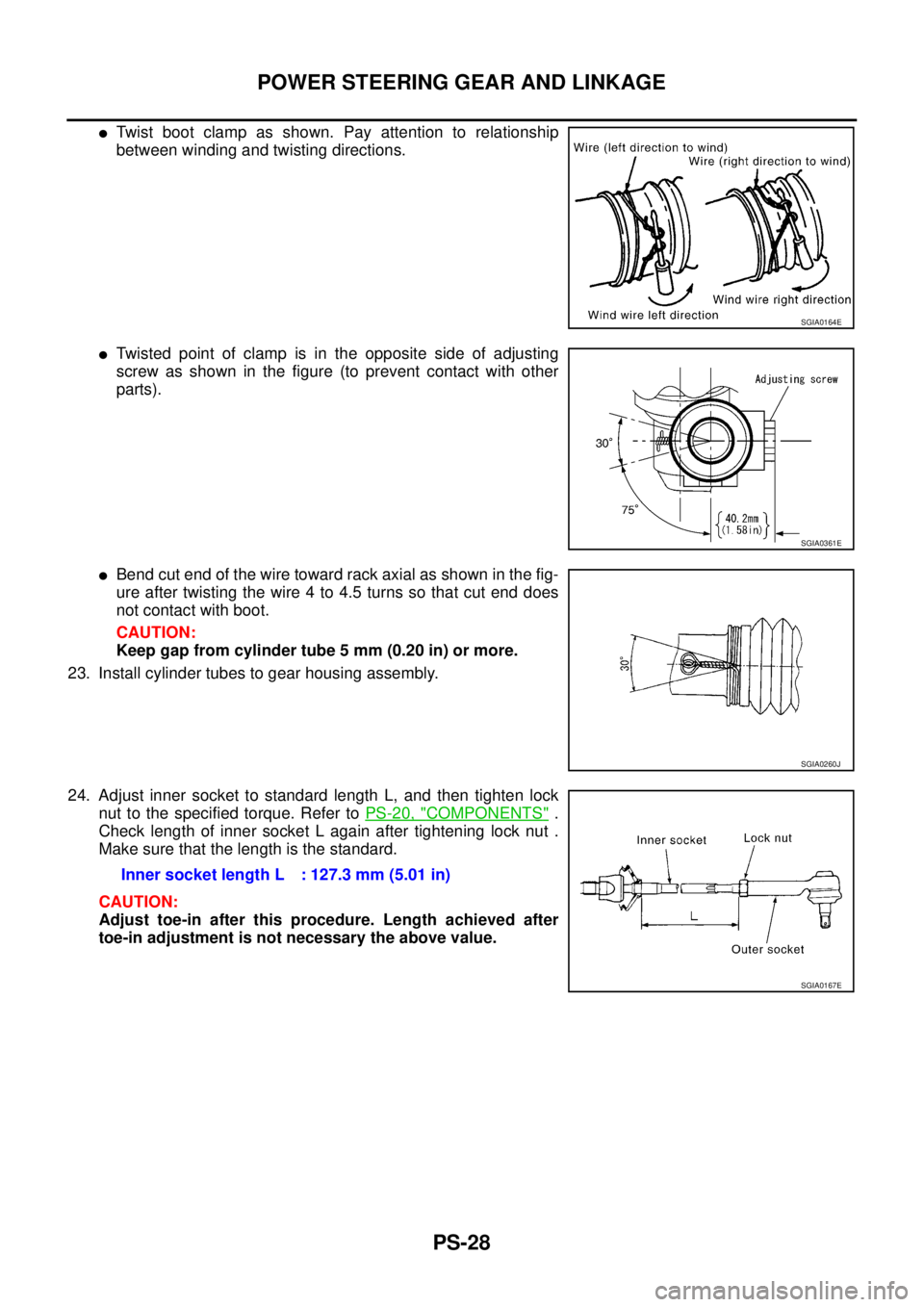
�Twist boot clamp as shown. Pay attention to relationship
between winding and twisting directions.
�Twisted point of clamp is in the opposite side of adjusting
screw as shown in the figure (to prevent contact with other
parts).
�Bend cut end of the wire toward rack axial as shown in the fig-
ure after twisting the wire 4 to 4.5 turns so that cut end does
not contact with boot.
CAUTION:
Keep gap from cylinder tube 5 mm (0.20 in) or more.
23. Install cylinder tubes to gear housing assembly.
24. Adjust inner socket to standard length L, and then tighten lock
nut to the specified torque. Refer to PS-20, "
COMPONENTS" .
Check length of inner socket L again after tightening lock nut .
Make sure that the length is the standard.
CAUTION:
Adjust toe-in after this procedure. Length achieved after
toe-in adjustment is not necessary the above value.
SGIA0164E
SGIA0361E
SGIA0260J
Inner socket length L : 127.3 mm (5.01 in)
SGIA0167E