Page 513 of 3502
REFRIGERANT LINES
ATC-135
C
D
E
F
G
H
I
K
L
MA
B
AT C
VQ Engine
1. Use a refrigerant collecting equipment (for HFC-134a) to discharge the refrigerant.
2. Remove engine undercover, using power tools.
3. Remove fender protector (right). Refer to EI-23, "
FENDER PROTECTOR" .
4. Remove A/C compressor belt. Refer to EM-14, "
DRIVE BELTS" (QR engine) or EM-128, "DRIVE BELTS"
(VQ engine).
5. Remove mounting bolts from low-pressure flexible hose and
high-pressure flexible hose.
CAUTION:
Cap or wrap the joint of the pipe with suitable material such
as vinyl tape to avoid the entry of air.
6. Disconnect compressor connector.
7. Remove idler pulley bracket (VQ engine). Refer to EM-129,
"Removal and Installation" .
8. Remove engine oil cooler hose bracket mounting bolts (VQ engine).
SJIA1165E
RJIA2983E
RJIA2985E
Page 674 of 3502

BL-16
HOOD
Removal and Installation of Hood Lock ControlBIS000VR
REMOVAL
Hood Lock and Hood Lock Cable
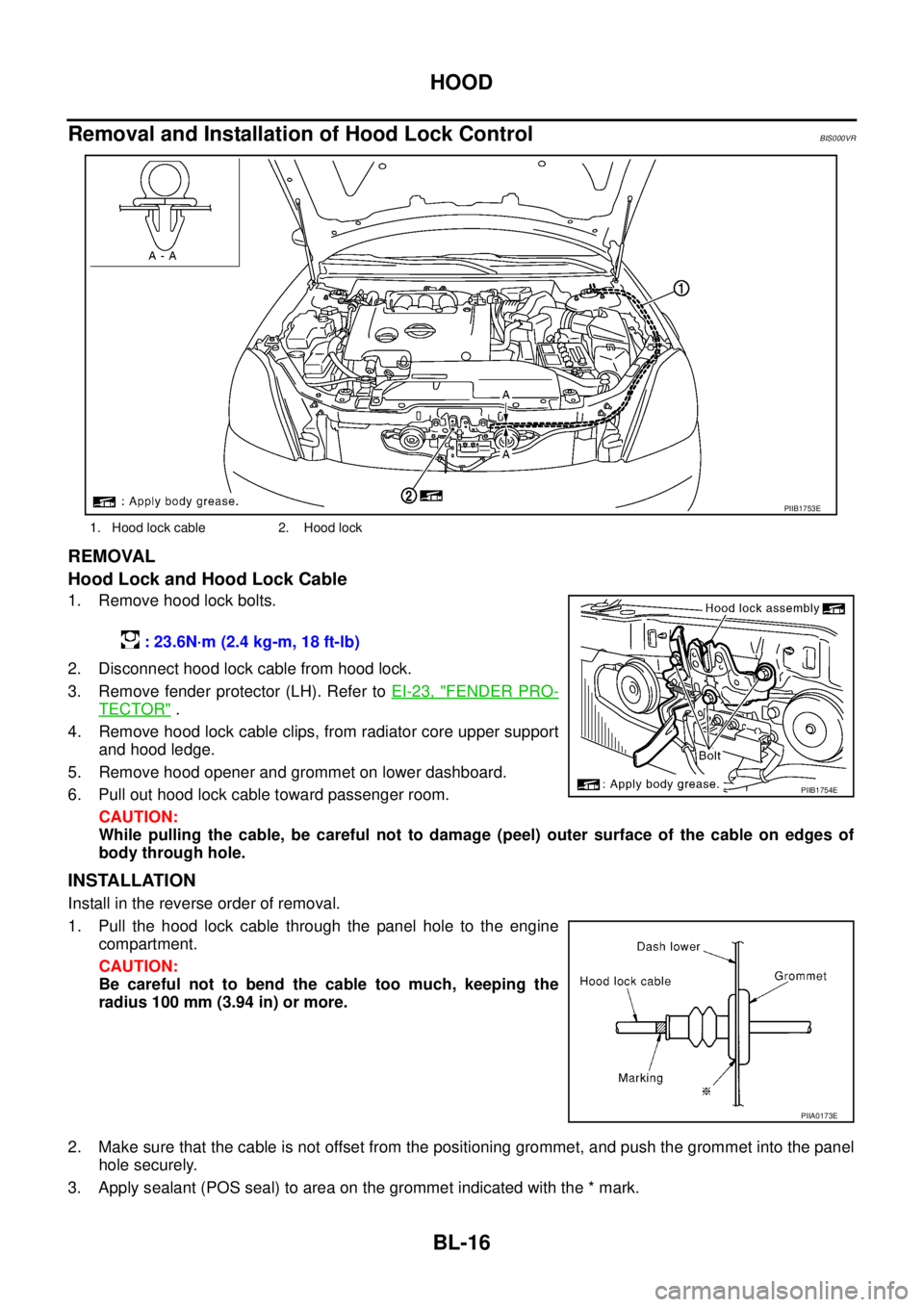
1. Remove hood lock bolts.
2. Disconnect hood lock cable from hood lock.
3. Remove fender protector (LH). Refer to EI-23, "
FENDER PRO-
TECTOR" .
4. Remove hood lock cable clips, from radiator core upper support
and hood ledge.
5. Remove hood opener and grommet on lower dashboard.
6. Pull out hood lock cable toward passenger room.
CAUTION:
While pulling the cable, be careful not to damage (peel) outer surface of the cable on edges of
body through hole.
INSTALLATION
Install in the reverse order of removal.
1. Pull the hood lock cable through the panel hole to the engine
compartment.
CAUTION:
Be careful not to bend the cable too much, keeping the
radius 100 mm (3.94 in) or more.
2. Make sure that the cable is not offset from the positioning grommet, and push the grommet into the panel
hole securely.
3. Apply sealant (POS seal) to area on the grommet indicated with the * mark.
1. Hood lock cable 2. Hood lock
PIIB1753E
: 23.6N·m (2.4 kg-m, 18 ft-lb)
PIIB1754E
PIIA0173E
Page 678 of 3502
BL-20
FRONT FENDER
FRONT FENDERPFP:63100
Removal and InstallationBIS000VU
REMOVAL
1. Remove the front bumper. Refer to EI-14, "FRONT BUMPER" .
2. Remove fender protector mounting clips and screws from out side. Refer to EI-23, "
FENDER PROTEC-
TOR" .
3. Remove center mud guard. Refer to EI-24, "
CENTER MUD GUARD" .
4. Remove bolts securing radiator core support side.
5. Remove hood hinge cover (rubber). Refer to EI-21, "
COWL TOP" .
6. Remove side turn signal lamp.
7. Remove bolts, and then remove front fender.
CAUTION:
While removing use a shop cloth to protect body from damaging.
INSTALLATION
Install in the reverse order of removal.
CAUTION:
�After installing, apply touch-up paint (the body color) onto the head of the front fender mounting
bolts.
�After installing, check front fender adjustment. Refer to BL-13, "Fitting Adjustment" and BL-119,
"Fitting Adjustment" .
1. Bolt 2. Front fender
PIIB0267E
Page 777 of 3502
DOOR
BL-119
C
D
E
F
G
H
J
K
L
MA
B
BL
DOORPFP:80100
Fitting AdjustmentBIS000XR
FRONT DOOR
Longitudinal Clearance and Surface Height Adjustment at Front End
1. Remove the fender protector. Refer toEI-23, "FENDER PROTECTOR" .
2. Loosen the hinge mounting bolts. Raise the front door at rear end to adjust.
REAR DOOR
Longitudinal Clearance and Surface Height Adjustment at Front End
1. Remove the center pillar lower garnish. Refer to EI-38, "BODY SIDE TRIM" .
2. Accessing from inside the vehicle, loosen the mounting nuts. Open the rear door, and raise the rear door
at rear end to adjust.
1. Front fender 2. Front door outer 3. Rear door outer
4. Rear fender 5. Front door hinge 6. Bolt
7. Nut 8. Rear door hinge (Upper) 9. Rear door hinge (Lower)
PIIB0277E
Page 2063 of 3502

FRONT BUMPER
EI-15
C
D
E
F
G
H
J
K
L
MA
B
EI
REMOVAL
1. Fully open hood assembly.
2. Remove front side of fender protector (LH/RH). Refer to EI-23, "
FENDER PROTECTOR" .
3. Disconnect the headlamp cleaner tube joint (1) of washer tank
(2). (With headlamp cleaner)
4. Remove clips of bumper fascia lower side.
5. Remove screws of bumper fascia left/right side.
6. Remove clips of bumper fascia upper side, and then pull out bumper fascia toward front of vehicle while
extending bumper fascia side surface toward vehicle outside.
7. Disconnect fog lamp harness connectors (LH/RH) after pulling out, and then remove bumper fascia.
CAUTION:
When removing bumper fascia, 2 workers are required so as to prevent it from dropping.
8. Remove fog lamp assembly (LH/RH). Refer to LT- 1 2 6 , "
FRONT FOG LAMP" .
9. Remove bumper energy absorber.
10. Remove bumper reinforcement mounting nuts and bumper reinforcement.
11. Unscrew bumper stay mounting bolts, and remove bumper stay (LH/RH).
12. Unscrew bumper side bracket mounting screws, and remove bumper side bracket (LH/RH).
INSTALLATION
Install in the reverse order of removal.
NOTE:
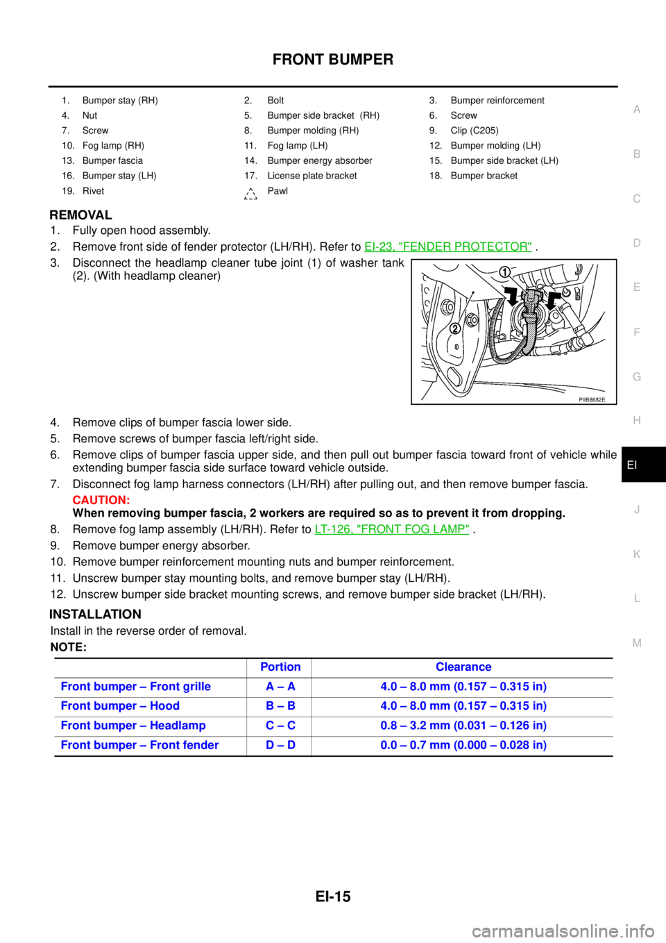
1. Bumper stay (RH) 2. Bolt 3. Bumper reinforcement
4. Nut 5. Bumper side bracket (RH) 6. Screw
7. Screw 8. Bumper molding (RH) 9. Clip (C205)
10. Fog lamp (RH) 11. Fog lamp (LH) 12. Bumper molding (LH)
13. Bumper fascia 14. Bumper energy absorber 15. Bumper side bracket (LH)
16. Bumper stay (LH) 17. License plate bracket 18. Bumper bracket
19. Rivet Pawl
PIIB8682E
Portion Clearance
Front bumper – Front grille A – A 4.0 – 8.0 mm (0.157 – 0.315 in)
Front bumper – Hood B – B 4.0 – 8.0 mm (0.157 – 0.315 in)
Front bumper – Headlamp C – C 0.8 – 3.2 mm (0.031 – 0.126 in)
Front bumper – Front fender D – D 0.0 – 0.7 mm (0.000 – 0.028 in)
Page 2071 of 3502
FENDER PROTECTOR
EI-23
C
D
E
F
G
H
J
K
L
MA
B
EI
FENDER PROTECTORPFP:63840
Removal and InstallationBIS0011I
REMOVAL
1. Remove rear end screw of fender protector (rear).
2. Remove rear end clip of fender protector (rear).
3. Remove plastic clamp from wheelhouse arches, and then remove fender protector (rear) from wheel-
house.
4. Remove front end screw of fender protector (front).
5. Remove front end clip of fender protector (front).
6. Remove fender protector (front) from wheelhouse.
INSTALLATION
Install in the reverse order of removal.
PIIA6253E
1. Fender protector (front) 2. Screw 3. Clip (C205)
4. Plastic clamp 5. Fender protector (rear)
Page 2239 of 3502
![NISSAN TEANA 2003 Service Manual AIR CLEANER AND AIR DUCT
EM-131
[VQ]
C
D
E
F
G
H
I
J
K
L
MA
EM
AIR CLEANER AND AIR DUCTPFP:16500
Removal and InstallationBBS004VP
REMOVAL
1. Remove air duct (inlet).
2. Disconnect harness connector NISSAN TEANA 2003 Service Manual AIR CLEANER AND AIR DUCT
EM-131
[VQ]
C
D
E
F
G
H
I
J
K
L
MA
EM
AIR CLEANER AND AIR DUCTPFP:16500
Removal and InstallationBBS004VP
REMOVAL
1. Remove air duct (inlet).
2. Disconnect harness connector](/manual-img/5/57392/w960_57392-2238.png)
AIR CLEANER AND AIR DUCT
EM-131
[VQ]
C
D
E
F
G
H
I
J
K
L
MA
EM
AIR CLEANER AND AIR DUCTPFP:16500
Removal and InstallationBBS004VP
REMOVAL
1. Remove air duct (inlet).
2. Disconnect harness connector from mass air flow sensor.
3. Disconnect PCV hose.
4. Remove air cleaner cases (upper and lower) with mass air flow sensor and air duct assembly disconnect-
ing their joints.
�Add mating marks as necessary for easier installation.
5. Remove mass air flow sensor from air cleaner case (upper), as necessary.
CAUTION:
Handle mass air flow sensor with following cares.
�Do not shock it.
�Do not disassemble it.
�Do not touch its sensor.
6. Remove resonator, removing left side fender protector (front), as necessary. Refer to EI-23, "
FENDER
PROTECTOR" .
1. Air cleaner case (lower) 2. Air cleaner filter 3. Air cleaner case (upper)
4. Air duct assembly 5. Harness bracket 6. Mass air flow sensor
7. O-ring 8. PCV hose 9. Air duct (inlet)
10. Clip 11. Resonator 12. Bracket
13. Grommet 14. Bracket
PBIC2451E
Page 2723 of 3502

HEADLAMP - XENON TYPE -
LT-35
C
D
E
F
G
H
I
J
L
MA
B
LT
Bulb ReplacementBKS001NG
HEADLAMP HIGH/LOW BEAM
1. Turn lighting switch OFF.
2. Disconnect negative battery cable or remove circuit fuse.
3. Remove washer tank inlet when replacing bulb RH. Refer to WW-38, "
Removal and Installation of Washer
Ta n k" .
Remove air cleaner case when replacing bulb LH. Refer to EM-17, "
Removal and Installation" (models
with QR engine), or EM-131, "
Removal and Installation" (models with VQ engine).
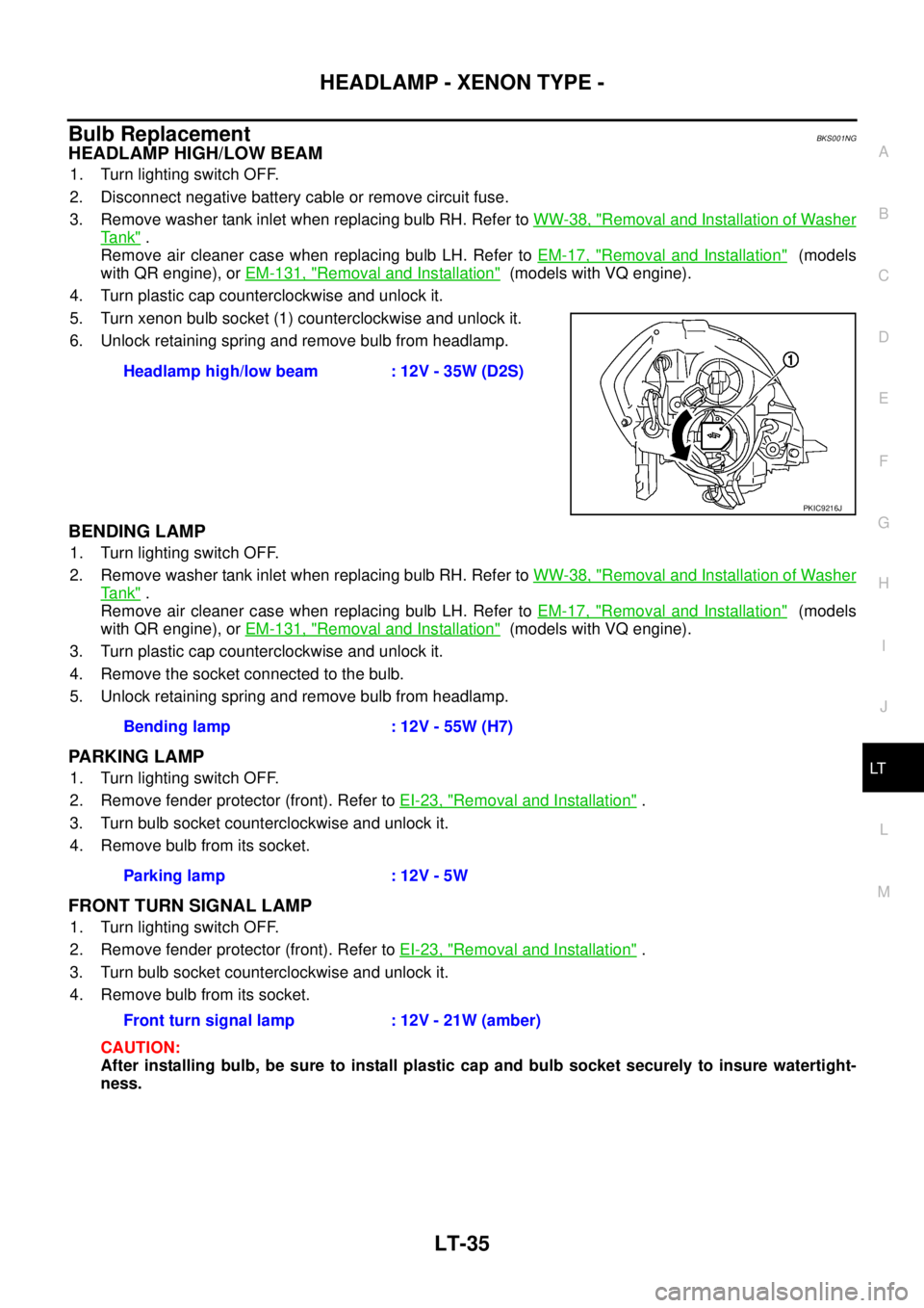
4. Turn plastic cap counterclockwise and unlock it.
5. Turn xenon bulb socket (1) counterclockwise and unlock it.
6. Unlock retaining spring and remove bulb from headlamp.
BENDING LAMP
1. Turn lighting switch OFF.
2. Remove washer tank inlet when replacing bulb RH. Refer to WW-38, "
Removal and Installation of Washer
Ta n k" .
Remove air cleaner case when replacing bulb LH. Refer to EM-17, "
Removal and Installation" (models
with QR engine), or EM-131, "
Removal and Installation" (models with VQ engine).
3. Turn plastic cap counterclockwise and unlock it.
4. Remove the socket connected to the bulb.
5. Unlock retaining spring and remove bulb from headlamp.
PARKING LAMP
1. Turn lighting switch OFF.
2. Remove fender protector (front). Refer to EI-23, "
Removal and Installation" .
3. Turn bulb socket counterclockwise and unlock it.
4. Remove bulb from its socket.
FRONT TURN SIGNAL LAMP
1. Turn lighting switch OFF.
2. Remove fender protector (front). Refer to EI-23, "
Removal and Installation" .
3. Turn bulb socket counterclockwise and unlock it.
4. Remove bulb from its socket.
CAUTION:
After installing bulb, be sure to install plastic cap and bulb socket securely to insure watertight-
ness.Headlamp high/low beam : 12V - 35W (D2S)
PKIC9216J
Bending lamp : 12V - 55W (H7)
Parking lamp : 12V - 5W
Front turn signal lamp : 12V - 21W (amber)