Page 246 of 3502

During removal and installation of air breather hose (air duct side) be careful of the following.
�Secure a mark (A) when ins")
AT-238
AIR BREATHER HOSE
REMOVAL AND INSTALLATION (QR20DE ENGINE MODELS)
During removal and installation of air breather hose (air duct side) be careful of the following.
�Secure a mark (A) when installing air breather hose (air duct
side) to air duct so as to see the mark.
�Install air breather hose (air duct side) to oil catch tank with a
mark (B) facing up. Insert air breather hose into oil catch tank
until it reaches the point where the winding radius stops.
CAUTION:
When installing an air breather hose (air duct side), be careful
not to be crushed or blocked by folding or bending the hose.
REMOVAL AND INSTALLATION (VQ23DE ENGINE MODELS)
During removal and installation of air breather hose (air duct side) be careful of the following.
�Secure a mark (A) when installing air breather hose (air duct
side) to air duct so as not to see the mark.
�Install air breather hose (air duct side) to oil catch tank with a
mark (B) facing up. Insert air breather hose into oil catch tank
until it reaches the point where the winding radius stops.
SCIA3022E
SCIA3020E
Page 247 of 3502
AIR BREATHER HOSE
AT-239
D
E
F
G
H
I
J
K
L
MA
B
AT
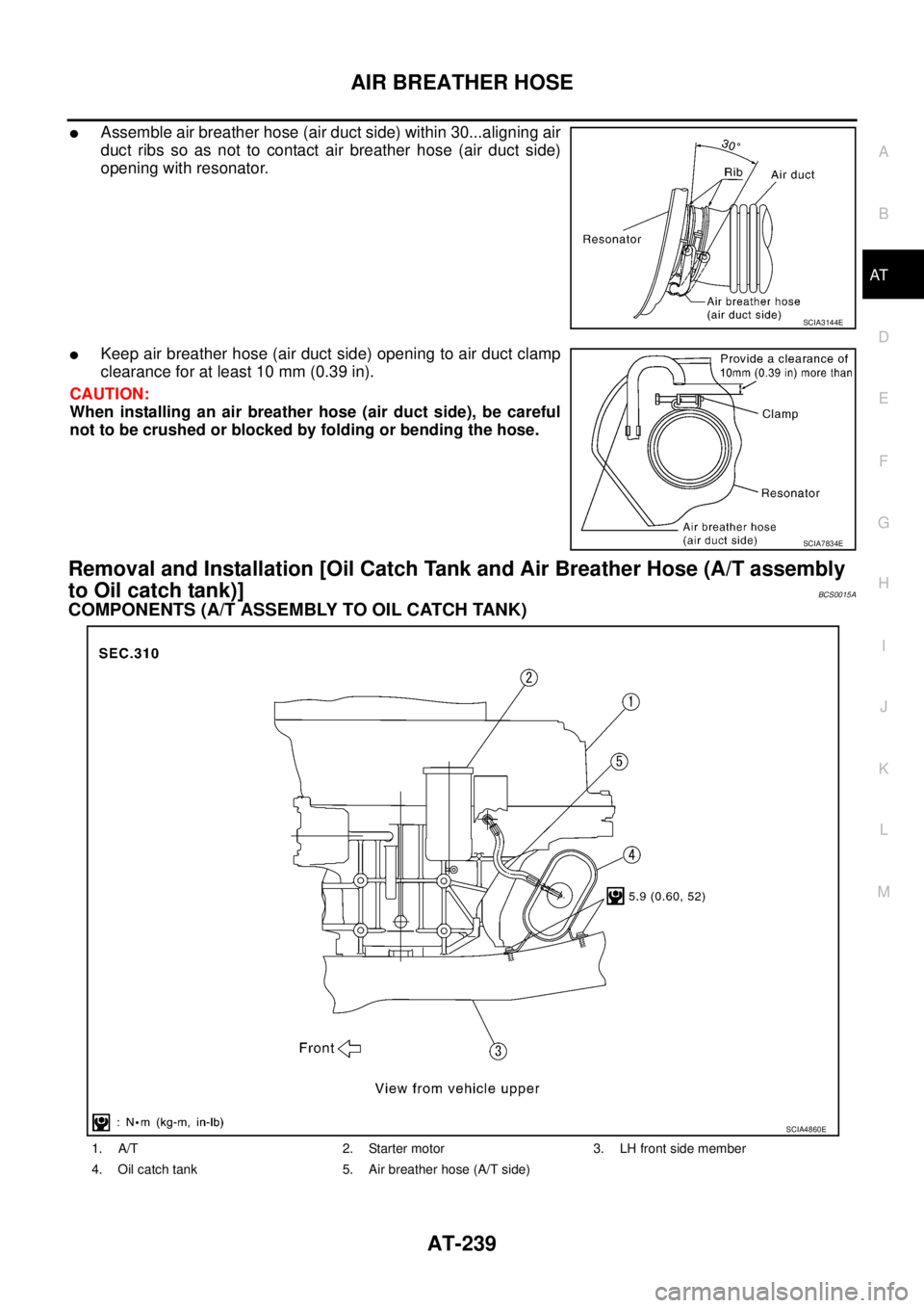
�Assemble air breather hose (air duct side) within 30...aligning air
duct ribs so as not to contact air breather hose (air duct side)
opening with resonator.
�Keep air breather hose (air duct side) opening to air duct clamp
clearance for at least 10 mm (0.39 in).
CAUTION:
When installing an air breather hose (air duct side), be careful
not to be crushed or blocked by folding or bending the hose.
Removal and Installation [Oil Catch Tank and Air Breather Hose (A/T assembly
to Oil catch tank)]
BCS0015A
COMPONENTS (A/T ASSEMBLY TO OIL CATCH TANK)
SCIA3144E
SCIA7834E
1. A/T 2. Starter motor 3. LH front side member
4. Oil catch tank 5. Air breather hose (A/T side)
SCIA4860E
Page 248 of 3502
AT-240
AIR BREATHER HOSE
REMOVAL AND INSTALLATION
Removal
1. Remove air duct. Refer to EM-131, "AIR CLEANER AND AIR DUCT" .
2. Remove air breather hose (air duct side and A/T side) from oil catch tank.
3. Remove oil catch tank from vehicle.
Installation
Note the following, and install in the reverse order of removal.
�Insert air breather hose (A/T side) [B] into tube stopper when
installing air breather hose (A/T side) to oil catch tank.
�Insert air breather hose (A/T side) [A] into the point where the
winding radius stops when installing air breather hose (A/T side)
to A/T assembly.
�Install air breather hose (air duct side). Refer to AT- 2 3 6 ,
"Removal and Installation [Air Breather Hose (Oil Catch Tank to
Air Duct)]" .
CAUTION:
When installing an air breather hose (A/T side), be careful not to
be crushed or blocked by folding or bending the hose.
SCIA7835E
Page 251 of 3502

TRANSAXLE ASSEMBLY
AT-243
D
E
F
G
H
I
J
K
L
MA
B
AT
4. Turn crankshaft, and remove four tightening bolts for drive plate
and torque converter.
CAUTION:
Crankshaft should be rotated clockwise, viewed from front
of engine.
5. Remove four bolts in figure.
6. Remove air breather hose. Refer to AT- 2 3 6 , "
AIR BREATHER
HOSE" .
7. Remove transaxle assembly and engine assembly together
from vehicle. Refer to EM-223, "
Removal and Installation" .
8. Remove front suspension member from transaxle assembly and
engine assembly. Refer to FSU-17, "
FRONT SUSPENSION
MEMBER" .
9. Remove drive shaft. Refer to FA X - 8 , "
FRONT DRIVE SHAFT" .
10. Remove front engine mounting bracket (front). Refer to EM-223,
"Removal and Installation" .
11. Remove rear engine mounting bracket (rear). Refer to EM-223, "
Removal and Installation" .
12. Remove A/T fluid level gauge.
13. Remove A/T fluid charging pipe.
14. Disconnect harness connector and wire harness.
15. Remove crankshaft position sensor (POS), from engine assembly. Refer to EM-145, "
Removal and Instal-
lation" .
CAUTION:
�Do not subject it to impact by dropping or hitting it.
�Do not disassemble.
�Do not allow metal filings, etc., to get on sensor's front edge magnetic area.
�Do not place in an area affected by magnetism.
16. Remove starter motor. Refer to SC-18, "
Removal and Installation" .
17. Remove engine mounting insulator (LH) and stopper. Refer to EM-223, "
Removal and Installation" .
18. Remove transaxle assembly fixing bolts with power tool.
19. Remove transaxle assembly from engine assembly.
CAUTION:
Secure torque converter to prevent it from dropping.
SCIA3138E
SCIA3139E
SCIA3143E
Page 253 of 3502

TRANSAXLE ASSEMBLY
AT-245
D
E
F
G
H
I
J
K
L
MA
B
AT
�Align the positions of tightening bolts for drive plate with those of
torque converter, and temporarily tighten bolts. Then, tighten
bolts with the specified torque.
CAUTION:
�When turning crankshaft, turn it clockwise as viewed from
front of engine.
�When tightening the tighten bolts for the torque converter
after fixing crankshaft pulley bolts, be sure to confirm the
tightening torque of crankshaft pulley mounting bolts.
Refer to EM-53, "
TIMING CHAIN" (QR engine), EM-173, "TIMING CHAIN" (VQ engine).
� After converter is installed to drive plate, rotate crankshaft several turns and make sure that tran-
saxle rotates freely without binding.
�Install POS sensor. Refer to EM-145, "Removal and Installation" .
�After completing installation, check for A/T fluid leakage, A/T fluid level, and positions of A/T. Refer to AT-
14, "Checking A/T Fluid" , AT- 2 1 5 , "Adjustment of A/T Position" , AT- 2 1 5 , "Checking of A/T Position" . : 52 N·m (5.3 kg-m, 38 ft-lb)
SCIA3138E
Page 255 of 3502
OVERHAUL
AT-247
D
E
F
G
H
I
J
K
L
MA
B
AT
1. Differential side bearing 2. Pinion mate gear thrust washer 3. Pinion mate gear
4. Pinion mate shaft 5. Lock pin 6. Side gear
7. Side gear thrust washer 8. Differential side bearing 9. Differential case
10. Final gear 11. Differential side bearing adjusting
shim12. Plug
13. O-ring 14. RH differential side oil seal 15. Torque converter
16. Converter housing 17. Differential lubricant tube 18. Clip
19. O-ring 20. Oil pump housing oil seal 21. Oil pump housing
22. O-ring 23. Outer gear 24. Inner gear
25. Oil pump cover 26. Oil pump assembly 27. Seal ring
28. Gasket
Page 259 of 3502
12. Bracket
13. Anchor end pin 14. Lock nut 15. Transaxle case
16. Brake band 17. B")
OVERHAUL
AT-251
D
E
F
G
H
I
J
K
L
MA
B
AT
10. O-ring 11. Turbine revolution sensor (power
train revolution sensor)12. Bracket
13. Anchor end pin 14. Lock nut 15. Transaxle case
16. Brake band 17. Bearing retainer 18. Seal ring
19. Radial needle bearing 20. Snap ring 21. Reduction pinion gear
22. Reduction pinion gear bearing inner
race23. Reduction pinion gear bearing outer
race24. Strut
25. O-ring 26. O-ring 27. Servo release accumulator piston
28. O-ring 29. Return spring 30. Control valve assembly
31. Oil pan gasket 32. Drain plug gasket 33. Drain plug
34. Magnet 35. Oil pan 36. Oil pan fitting bolt
37. Low & reverse brake tube 38. Oil sleeve 39. O-ring
40. Snap ring 41. O-ring 42. N-D accumulator piston
43. Return spring 44. Lip seal 45. Parking rod
46. Retaining pin 47. Manual shaft oil seal 48. Detent spring
49. Manual shaft 50. Retaining pin 51. Manual plate
52. Parking rod plate 53. O/D servo piston 54. O/D servo piston retainer
55. O/D servo piston retainer fitting bolt 56. O-ring 57. D-ring
58. Servo piston retainer 59. O-ring 60. E-ring
61. Spring retainer 62. O/D servo return spring 63. D-ring
64. Band servo piston 65. Band servo thrust washer 66. Band servo piston stem
67. 2nd servo return spring 68. Parking pawl 69. Parking shaft
70. Return spring 71. Paring pawl spacer 72. PNP switch
73. Idler gear bearing 74. Idler gear 75. Idler gear lock nut
76. Reduction pinion gear adjusting
shim77. Output shaft adjusting shim 78. Side cover
Refer to GI section to make sure icons (symbol marks) in the figure. Refer to GI-10, "
Components" .
However, refer to the following symbol for others.
: Apply locking sealant (Loctite #518).
Page 263 of 3502
DISASSEMBLY
AT-255
D
E
F
G
H
I
J
K
L
MA
B
AT
DISASSEMBLYPFP:31020
DisassemblyBCS001OI
1. Drain ATF through drain plug.
2. Remove drain plug gasket from drain plug.
3. Remove torque converter.
4. Check torque converter one-way clutch using check tool as
shown in the figure.
a. Insert check tool into groove of bearing support built into one-
way clutch outer race.
b. When fixing bearing support with check tool, rotate one- way
clutch spline using screwdriver.
c. Check that inner race rotates clockwise only. If not, replace
torque converter assembly.
SCIA0003E
SAT008D
SAT009D
 from oil catch ta")

