Page 270 of 3502
AT-262
DISASSEMBLY
d. Remove thrust washer and bearing race from oil pump assem-
bly.
35. Remove brake band according to the following procedures.
a. Loosen lock nut, and then remove anchor end pin and lock nut
as a set from transaxle case.
b. Remove brake band and strut from transaxle case.
�To prevent brake linings from cracking or peeling, do not
stretch the flexible band unnecessarily. When removing
brake band, always secure it with a clip as shown in the
figure.
Leave the clip in position after removing brake band.
SCIA3629E
SCIA4869E
SAT196F
SAT039D
Page 274 of 3502
AT-266
DISASSEMBLY
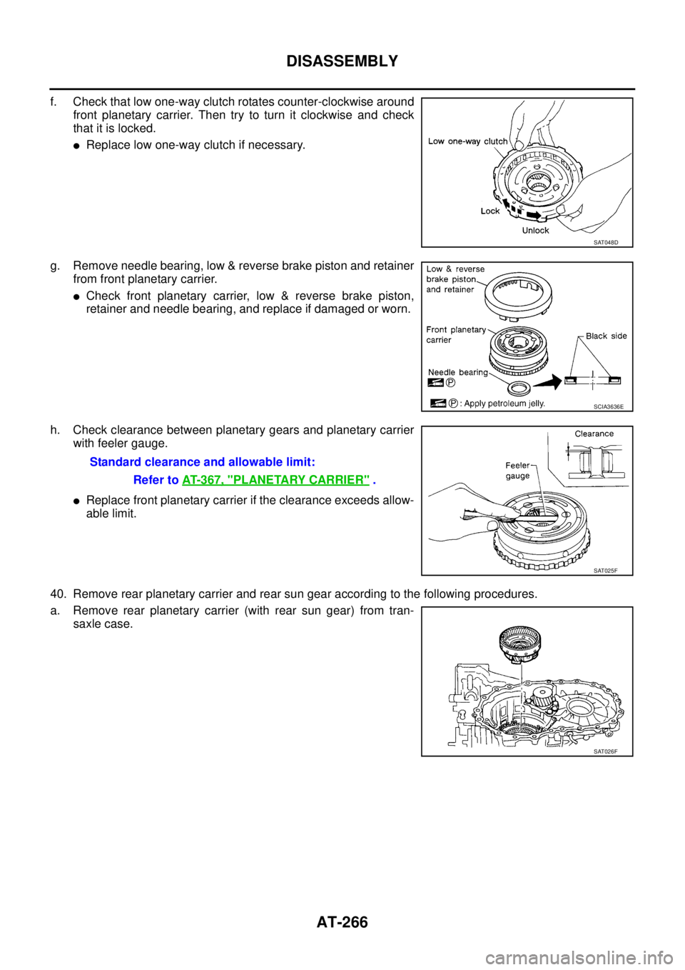
f. Check that low one-way clutch rotates counter-clockwise around
front planetary carrier. Then try to turn it clockwise and check
that it is locked.
�Replace low one-way clutch if necessary.
g. Remove needle bearing, low & reverse brake piston and retainer
from front planetary carrier.
�Check front planetary carrier, low & reverse brake piston,
retainer and needle bearing, and replace if damaged or worn.
h. Check clearance between planetary gears and planetary carrier
with feeler gauge.
�Replace front planetary carrier if the clearance exceeds allow-
able limit.
40. Remove rear planetary carrier and rear sun gear according to the following procedures.
a. Remove rear planetary carrier (with rear sun gear) from tran-
saxle case.
SAT048D
SCIA3636E
Standard clearance and allowable limit:
Refer to AT- 3 6 7 , "
PLANETARY CARRIER" .
SAT025F
SAT026F
Page 278 of 3502
AT-270
DISASSEMBLY
47. Disassemble reduction pinion gear according to the following
procedures.
a. Set manual shaft to “P” position to fix idler gear.
b. Unlock idler gear lock nut with pin punch.
c. Remove idler gear lock nut.
d. Remove idler gear with puller.
e. Remove reduction pinion gear.
f. Remove reduction pinion gear adjusting shim from reduction
pinion gear.
48. Remove return spring and parking pawl spacer with flat-bladed
screwdriver from parking shaft.
49. Draw out parking shaft and remove parking pawl from transaxle
case.
�Check parking pawl and parking shaft, and replace it dam-
aged or worn.
SAT037F
SAT061D
SAT841DC
SCIA4880E
SCIA4881E
Page 330 of 3502
AT-322
REPAIR FOR COMPONENT PARTS
3. Install thrust washer on rear internal gear.
CAUTION:
Align pawls of thrust washer with holes of rear internal
gear.
4. Install bearing race on rear internal gear.
5. Install forward clutch hub on rear internal gear.
CAUTION:
�Check operation of forward one-way clutch.
Hold rear internal gear and turn forward clutch hub.
Check forward clutch hub for correct locking and unlock-
ing directions.
�If not as shown in figure, check installation direction of
forward one-way clutch.
6. Install thrust washer and overrun clutch hub on forward clutch
hub.
CAUTION:
�Align pawls of thrust washer with holes of overrun clutch
hub.
�Align projections of rear internal gear with holes of over-
run clutch hub.
SCIA3690E
SCIA3659E
AAT426
SCIA3692E
Page 331 of 3502
REPAIR FOR COMPONENT PARTS
AT-323
D
E
F
G
H
I
J
K
L
MA
B
AT
Output Shaft, Idler Gear, Reduction Pinion Gear and Bearing RetainerBCS001OT
COMPONENTS
DISASSEMBLY
1. Remove seal rings from output shaft and bearing retainer.
1. Idler gear lock nut 2. Idler gear 3. Reduction pinion gear adjusting
shim
4. Idler gear bearing 5. Reduction pinion gear bearing outer
race6. Reduction pinion gear bearing inner
race
7. Reduction pinion gear 8. Snap ring 9. Radial needle bearing
10. Seal ring 11. Bearing retainer 12. Needle bearing
13. Seal ring 14. Out put shaft 15. Out put shaft bearing
16. Output shaft adjusting shim
Refer to GI section to make sure icons (symbol marks) in the figure. Refer to GI-10, "
Components" .
SCIA7810E
SCIA3660E
Page 337 of 3502
REPAIR FOR COMPONENT PARTS
AT-329
D
E
F
G
H
I
J
K
L
MA
B
AT
Band Servo Piston AssemblyBCS001OU
COMPONENTS
DISASSEMBLY
1. Remove O/D servo piston retainer fitting bolts.
2. Apply compressed air to oil hole in transaxle case to remove O/
D servo piston assembly and band servo piston assembly.
CAUTION:
Hold band servo piston assembly with a rag or nylon waste.
3. Remove 2nd servo return spring from transaxle case.
1. Lock nut 2. Anchor end pin 3. Brake band
4. Strut 5. O-ring 6. Servo piston retainer
7. D-ring 8. O/D servo piston 9. O-ring
10. O/D servo piston retainer 11. O/D servo piston retainer fitting bolt 12. E-ring
13. Spring retainer 14. O/D servo return spring 15. D-ring
16. Band servo piston 17. Band servo thrust washer 18. Band servo piston stem
19. 2nd servo return spring
Refer to GI section to make sure icons (symbol marks) in the figure. Refer to GI-10, "
Components" .
SCIA7811E
AAT879
SCIA4447E
Page 338 of 3502
AT-330
REPAIR FOR COMPONENT PARTS
4. Apply compressed air to oil hole in O/D servo piston retainer to
remove O/D servo piston from O/D servo piston retainer.
CAUTION:
Hold O/D servo piston while applying compressed air.
5. Remove D-ring from O/D servo piston.
6. Remove O-rings (1), (2) and (3) from O/D servo piston retainer
(4).
(1): O-ring (small diameter)
(2): O-ring (medium diameter)
(3): O-ring (large diameter)
7. Remove band servo piston assembly from servo piston retainer
by pushing it forward.
8. Place band servo piston stem end on a wooden block. While
pushing spring retainer down, remove E-ring.
AAT880
SCIA3689E
SCIA7732E
SAT293D
SAT294D
Page 340 of 3502
AT-332
REPAIR FOR COMPONENT PARTS
ASSEMBLY
1. Install D-rings to band servo piston.
CAUTION:
Be careful to position of each D-ring.
2. Install band servo piston stem, band servo thrust washer, O/D
servo return spring and spring retainer to band servo piston.
3. Place band servo piston stem end on a wooden block. While
pushing spring retainer down, install E-ring.
4. Install O-rings to servo piston retainer.
CAUTION:
Be careful to position of each O-ring.
SCIA3688E
SCIA4746E
SCIA4336E
SCIA3671E