Page 3480 of 3502
WW-42
HEADLAMP WASHER
SchematicBKS002EM
TKWM4644E
Page 3481 of 3502
HEADLAMP WASHER
WW-43
C
D
E
F
G
H
I
J
L
MA
B
WW
Wiring Diagram — HLC —BKS002CD
TKWM4645E
Page 3482 of 3502
WW-44
HEADLAMP WASHER
TKWM4646E
Page 3483 of 3502
HEADLAMP WASHER
WW-45
C
D
E
F
G
H
I
J
L
MA
B
WW
TKWM4647E
Page 3484 of 3502

WW-46
HEADLAMP WASHER
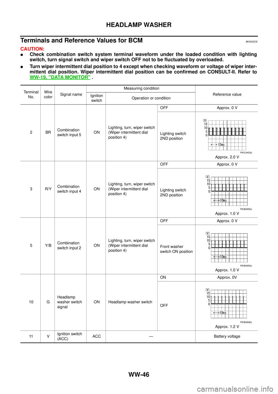
Terminals and Reference Values for BCMBKS002CE
CAUTION:
�Check combination switch system terminal waveform under the loaded condition with lighting
switch, turn signal switch and wiper switch OFF not to be fluctuated by overloaded.
�Turn wiper intermittent dial position to 4 except when checking waveform or voltage of wiper inter-
mittent dial position. Wiper intermittent dial position can be confirmed on CONSULT-II. Refer to
WW-19, "
DATA MONITOR" .
Terminal
No.Wire
colorSignal nameMeasuring condition
Reference value
Ignition
switchOperation or condition
2BRCombination
switch input 5ONLighting, turn, wiper switch
(Wiper intermittent dial
position 4)OFF Approx. 0 V
Lighting switch
2ND position
Approx. 2.0 V
3R/YCombination
switch input 4ONLighting, turn, wiper switch
(Wiper intermittent dial
position 4)OFF Approx. 0 V
Lighting switch
2ND position
Approx. 1.0 V
5Y/BCombination
switch input 2ONLighting, turn, wiper switch
(Wiper intermittent dial
position 4)OFF Approx. 0 V
Front washer
switch ON position
Approx. 1.0 V
10 GHeadlamp
washer switch
signalON Headlamp washer switchON Approx. 0V
OFF
Approx. 1.2 V
11 VIgnition switch
(ACC)ACC — Battery voltage
PKIC4459J
PKIB4959J
PKIB4959J
PKIB4958J
Page 3485 of 3502
HEADLAMP WASHER
WW-47
C
D
E
F
G
H
I
J
L
MA
B
WW
34 L/WCombination
switch output 3ONLighting, turn, wiper switch
(Wiper intermittent dial
position 4)OFF
Approx. 7.2 V
Lighting switch
2ND position
Approx. 1.2 V
35 G/BCombination
switch output 2ONLighting, turn, wiper switch
(Wiper intermittent dial
position 4)OFF
Approx. 7.2 V
Lighting switch
2ND position
Approx. 1.2 V
36 G/WCombination
switch output 1ONLighting, turn, wiper switch
(Wiper intermittent dial
position 4)OFF
Approx. 7.2 V
Front washer
switch ON position
Approx. 1.2 V
38 RIgnition switch
(ON) ON — Battery voltage Te r m i n a l
No.Wire
colorSignal nameMeasuring condition
Reference value
Ignition
switchOperation or condition
PKIB4960J
PKIB4958J
PKIB4960J
PKIB4958J
PKIB4960J
PKIB4958J
Page 3486 of 3502

WW-48
HEADLAMP WASHER
Terminals and Reference Values for IPDM E/RBKS002CF
How to Proceed with Trouble DiagnosisBKS002CG
1. Confirm the symptoms and customer complaint.
2. Understand operation description and function description. Refer to WW-40, "
System Description" .
3. Perform the Preliminary Check. Refer to WW-49, "
Preliminary Check" .
4. Check symptom and repair or replace the cause of malfunction.
5. Does headlamp washer operate normally? If YES, GO TO 6. If NO, GO TO 4.
6. INSPECTION END
39 L CAN-H — — —
40 P CAN-L — — —
52 B Ground ON — Approx. 0 V
55 W/BBattery power
supplyOFF — Battery voltage Terminal
No.Wire
colorSignal nameMeasuring condition
Reference value
Ignition
switchOperation or condition
Terminal
No.Wire
colorSignal nameMeasuring condition
Reference value
Ignition
switchOperation or condition
38 B Ground ON — Approx. 0 V
48 L CAN− H—— —
49 P CAN− L—— —
58 G/W Headlamp washer relay signal ONHeadlamp washer
switch positionOFF Battery voltage
ON Approx. 0 V
60 B Ground ON — Approx. 0 V
Page 3487 of 3502

HEADLAMP WASHER
WW-49
C
D
E
F
G
H
I
J
L
MA
B
WW
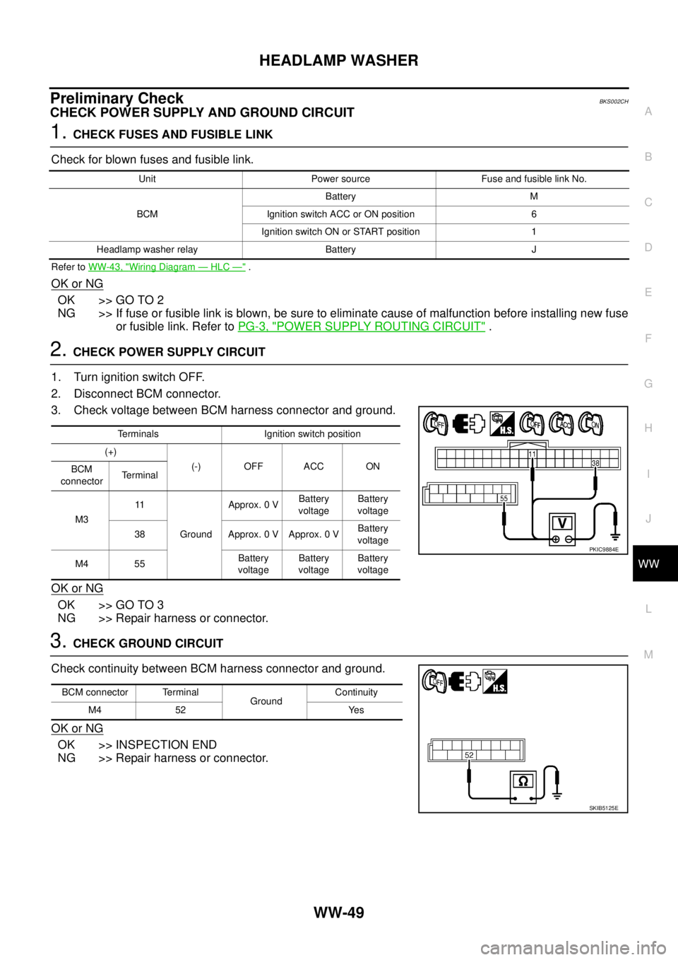
Preliminary CheckBKS002CH
CHECK POWER SUPPLY AND GROUND CIRCUIT
1. CHECK FUSES AND FUSIBLE LINK
Check for blown fuses and fusible link.
Refer to WW-43, "Wiring Diagram — HLC —" .
OK or NG
OK >> GO TO 2
NG >> If fuse or fusible link is blown, be sure to eliminate cause of malfunction before installing new fuse
or fusible link. Refer to PG-3, "
POWER SUPPLY ROUTING CIRCUIT" .
2. CHECK POWER SUPPLY CIRCUIT
1. Turn ignition switch OFF.
2. Disconnect BCM connector.
3. Check voltage between BCM harness connector and ground.
OK or NG
OK >> GO TO 3
NG >> Repair harness or connector.
3. CHECK GROUND CIRCUIT
Check continuity between BCM harness connector and ground.
OK or NG
OK >> INSPECTION END
NG >> Repair harness or connector.
Unit Power source Fuse and fusible link No.
BCMBattery M
Ignition switch ACC or ON position 6
Ignition switch ON or START position 1
Headlamp washer relay Battery J
Terminals Ignition switch position
(+)
(-) OFF ACC ON
BCM
connectorTe r m i n a l
M311
GroundApprox. 0 VBattery
voltageBattery
voltage
38 Approx. 0 V Approx. 0 VBattery
voltage
M4 55Battery
voltageBattery
voltageBattery
voltage
PKIC9884E
BCM connector Terminal
GroundContinuity
M4 52 Yes
SKIB5125E