Page 2839 of 3502
REAR FOG LAMP
LT-151
C
D
E
F
G
H
I
J
L
MA
B
LT
Rear Fog Lamp Does Not Go OFFBKS001PJ
1. PERFORM BCM ACTIVE TEST
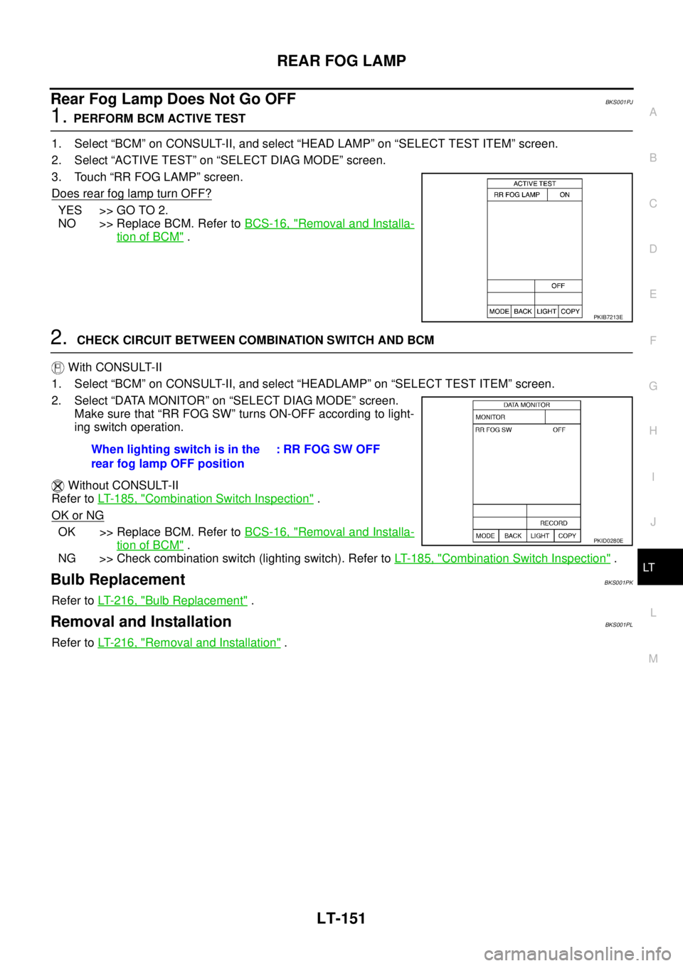
1. Select “BCM” on CONSULT-II, and select “HEAD LAMP” on “SELECT TEST ITEM” screen.
2. Select “ACTIVE TEST” on “SELECT DIAG MODE” screen.
3. Touch “RR FOG LAMP” screen.
Does rear fog lamp turn OFF?
YES >> GO TO 2.
NO >> Replace BCM. Refer to BCS-16, "
Removal and Installa-
tion of BCM" .
2. CHECK CIRCUIT BETWEEN COMBINATION SWITCH AND BCM
With CONSULT-II
1. Select “BCM” on CONSULT-II, and select “HEADLAMP” on “SELECT TEST ITEM” screen.
2. Select “DATA MONITOR” on “SELECT DIAG MODE” screen.
Make sure that “RR FOG SW” turns ON-OFF according to light-
ing switch operation.
Without CONSULT-II
Refer to LT- 1 8 5 , "
Combination Switch Inspection" .
OK or NG
OK >> Replace BCM. Refer to BCS-16, "Removal and Installa-
tion of BCM" .
NG >> Check combination switch (lighting switch). Refer to LT- 1 8 5 , "
Combination Switch Inspection" .
Bulb ReplacementBKS001PK
Refer to LT- 2 1 6 , "Bulb Replacement" .
Removal and InstallationBKS001PL
Refer to LT- 2 1 6 , "Removal and Installation" .
PKIB7213E
When lighting switch is in the
rear fog lamp OFF position: RR FOG SW OFF
PKID0280E
Page 2852 of 3502
LT-164
TURN SIGNAL AND HAZARD WARNING LAMPS
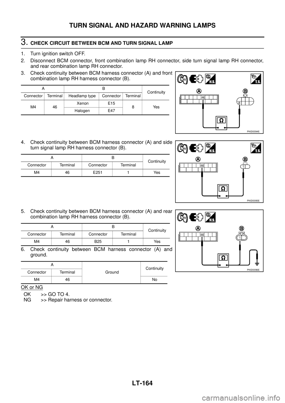
3. CHECK CIRCUIT BETWEEN BCM AND TURN SIGNAL LAMP
1. Turn ignition switch OFF.
2. Disconnect BCM connector, front combination lamp RH connector, side turn signal lamp RH connector,
and rear combination lamp RH connector.
3. Check continuity between BCM harness connector (A) and front
combination lamp RH harness connector (B).
4. Check continuity between BCM harness connector (A) and side
turn signal lamp RH harness connector (B).
5. Check continuity between BCM harness connector (A) and rear
combination lamp RH harness connector (B).
6. Check continuity between BCM harness connector (A) and
ground.
OK or NG
OK >> GO TO 4.
NG >> Repair harness or connector.
AB
Continuity
Connector Terminal Headlamp type Connector Terminal
M4 46 Xenon E15
8Yes
Halogen E47
PKID0094E
AB
Continuity
Connector Terminal Connector Terminal
M4 46 E251 1 Yes
PKID0095E
AB
Continuity
Connector Terminal Connector Terminal
M4 46 B25 1 Yes
A
GroundContinuity
Connector Terminal
M4 46 No
PKID0096E
Page 2854 of 3502
LT-166
TURN SIGNAL AND HAZARD WARNING LAMPS
5. CHECK CIRCUIT BETWEEN TURN SIGNAL LAMP AND GROUND
1. Turn ignition switch OFF.
2. Check continuity between front combination lamp RH harness connector and ground.
3. Check continuity between side turn signal lamp RH harness
connector and ground.
4. Check continuity between rear combination lamp RH harness
connector and ground.
OK or NG
OK >> Check turn signal lamps RH bulbs.
NG >> Repair harness or connector.
Headlamp typeFront combination
lamp RH connectorTerminal
GroundContinuity
Xenon E15
4Yes
Conventional E47
SKIB8819E
Side turn signal
lamp RH connectorTerminal
GroundContinuity
E251 2 Yes
PKID0098E
Rear combination
lamp RH connectorTerminal
GroundContinuity
B25 2 Yes
PKID0099E
Page 2856 of 3502
LT-168
TURN SIGNAL AND HAZARD WARNING LAMPS
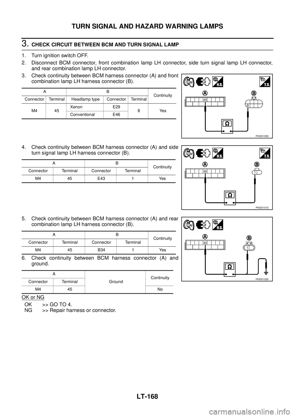
3. CHECK CIRCUIT BETWEEN BCM AND TURN SIGNAL LAMP
1. Turn ignition switch OFF.
2. Disconnect BCM connector, front combination lamp LH connector, side turn signal lamp LH connector,
and rear combination lamp LH connector.
3. Check continuity between BCM harness connector (A) and front
combination lamp LH harness connector (B).
4. Check continuity between BCM harness connector (A) and side
turn signal lamp LH harness connector (B).
5. Check continuity between BCM harness connector (A) and rear
combination lamp LH harness connector (B).
6. Check continuity between BCM harness connector (A) and
ground.
OK or NG
OK >> GO TO 4.
NG >> Repair harness or connector.
AB
Continuity
Connector Terminal Headlamp type Connector Terminal
M4 45 Xenon E29
8Yes
Conventional E46
PKID0100E
AB
Continuity
Connector Terminal Connector Terminal
M4 45 E43 1 Yes
PKID0101E
AB
Continuity
Connector Terminal Connector Terminal
M4 45 B34 1 Yes
A
GroundContinuity
Connector Terminal
M4 45 No
PKID0102E
Page 2858 of 3502
LT-170
TURN SIGNAL AND HAZARD WARNING LAMPS
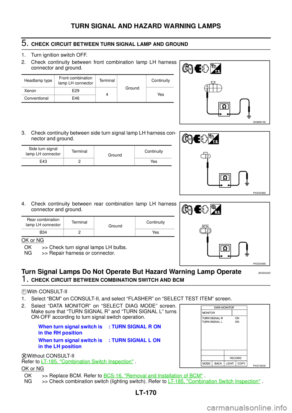
5. CHECK CIRCUIT BETWEEN TURN SIGNAL LAMP AND GROUND
1. Turn ignition switch OFF.
2. Check continuity between front combination lamp LH harness
connector and ground.
3. Check continuity between side turn signal lamp LH harness con-
nector and ground.
4. Check continuity between rear combination lamp LH harness
connector and ground.
OK or NG
OK >> Check turn signal lamps LH bulbs.
NG >> Repair harness or connector.
Turn Signal Lamps Do Not Operate But Hazard Warning Lamp OperateBKS0040D
1. CHECK CIRCUIT BETWEEN COMBINATION SWITCH AND BCM
With CONSULT-II
1. Select “BCM” on CONSULT-II, and select “FLASHER” on “SELECT TEST ITEM” screen.
2. Select “DATA MONITOR” on “SELECT DIAG MODE” screen.
Make sure that “TURN SIGNAL R” and “TURN SIGNAL L” turns
ON-OFF according to turn signal switch operation.
Without CONSULT-II
Refer to LT- 1 8 5 , "
Combination Switch Inspection" .
OK or NG
OK >> Replace BCM. Refer to BCS-16, "Removal and Installation of BCM" .
NG >> Check combination switch (lighting switch). Refer to LT- 1 8 5 , "
Combination Switch Inspection" .
Headlamp typeFront combination
lamp LH connectorTerminal
GroundContinuity
Xenon E29
4Yes
Conventional E46
SKIB8819E
Side turn signal
lamp LH connectorTerminal
GroundContinuity
E43 2 Yes
PKID0098E
Rear combination
lamp LH connectorTerminal
GroundContinuity
B34 2 Yes
PKID0099E
When turn signal switch is
in the RH position: TURN SIGNAL R ON
When turn signal switch is
in the LH position: TURN SIGNAL L ON
PKIA7600E
Page 2872 of 3502

LT-184
COMBINATION SWITCH
CONSULT-II BASIC OPERATION
Refer to GI-34, "CONSULT-II Start Procedure" .
DATA MONITOR
Operation Procedure
1. Touch “COMB SW” on “SELECT TEST ITEM” screen.
2. Touch “DATA MONITOR” on “SELECT DIAG MODE” screen.
3. Touch either “ALL SIGNALS” or “SELECTION FROM MENU” on “SELECT MONITOR ITEM” screen.
4. When “ALL SIGNALS” is selected, all the items will be monitored. When “SELECTION FROM MENU” is
selected, touch individual items to be monitored.
5. Touch “START”.
6. Touch “RECORD” while monitoring, then the status of the monitored item can be recorded. To stop
recording, touch “STOP”.
Display Item List
NOTE:
This item is displayed, but cannot be monitored.ALL SIGNALS Monitors all the items.
SELECTION FROM MENU Selects items and monitor them.
Monitor item name Contents
TURN SIGNAL R “ON/OFF” Displays “Turn Right (ON)/other (OFF)” status, determined from lighting switch signal.
TURN SIGNAL L “ON/OFF” Displays “Turn Left (ON)/other (OFF)” status, determined from lighting switch signal.
HI BEAM SW “ON/OFF”Displays status (high beam switch: ON/others: OFF) of high beam switch judged from lighting
switch signal.
HEAD LAMP SW 1 “ON/OFF”Displays status (headlamp switch 1: ON/others: OFF) of headlamp switch 1 judged from light-
ing switch signal.
HEAD LAMP SW 2 “ON/OFF”Displays status (headlamp switch 2: ON/others: OFF) of headlamp switch 2 judged from light-
ing switch signal.
LIGHT SW 1ST “ON/OFF”Displays status (lighting switch 1ST or 2ND position: ON/others: OFF) of lighting switch
judged from lighting switch signal.
PASSING SW “ON/OFF”Displays status (flash-to-pass switch: ON/others: OFF) of flash-to-pass switch judged from
lighting switch signal.
AUTO LIGHT SW “ON/OFF” Displays “Auto light switch (ON)/other (OFF)” status, determined from lighting switch signal.
FR FOG SW “ON/OFF”Displays “front fog lamp switch (ON)/other (OFF)” status, determined from lighting switch sig-
nal.
RR FOG SW “ON/OFF”Displays “rear fog lamp switch (ON)/other (OFF)” status, determined from lighting switch sig-
nal.
FR WIPER HI “ON/OFF” Displays “Front Wiper HI (ON)/other (OFF)” status, determined from wiper switch signal.
FR WIPER LOW “ON/OFF” Displays “Front Wiper LOW (ON)/other (OFF)” status, determined from wiper switch signal.
FR WIPER INT “ON/OFF” Displays “Front Wiper INT (ON)/other (OFF)” status, determined from wiper switch signal.
FR WASHER SW “ON/OFF” Displays “Front Washer Switch (ON)/other (OFF)” status, determined from wiper switch signal.
INT VOLUME “1 - 7” Displays intermittent operation knob setting (1 - 7), determined from wiper switch signal.
RR WIPER ON
NOTE“OFF” —
RR WIPER INT
NOTE“OFF” —
RR WASHER SW
NOTE“OFF” —
Page 2894 of 3502
LT-206
PARKING, LICENSE PLATE AND TAIL LAMPS
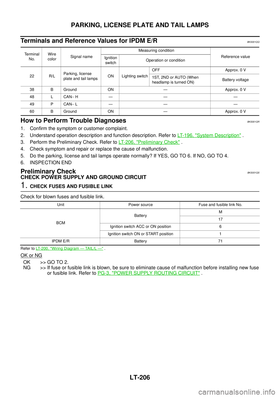
Terminals and Reference Values for IPDM E/RBKS001QQ
How to Perform Trouble DiagnosesBKS001QR
1. Confirm the symptom or customer complaint.
2. Understand operation description and function description. Refer to LT- 1 9 6 , "
System Description" .
3. Perform the Preliminary Check. Refer to LT- 2 0 6 , "
Preliminary Check" .
4. Check symptom and repair or replace the cause of malfunction.
5. Do the parking, license and tail lamps operate normally? If YES, GO TO 6. If NO, GO TO 4.
6. INSPECTION END
Preliminary CheckBKS001QS
CHECK POWER SUPPLY AND GROUND CIRCUIT
1. CHECK FUSES AND FUSIBLE LINK
Check for blown fuses and fusible link.
Refer to LT-200, "Wiring Diagram — TAIL/L —" .
OK or NG
OK >> GO TO 2.
NG >> If fuse or fusible link is blown, be sure to eliminate cause of malfunction before installing new fuse
or fusible link. Refer to PG-3, "
POWER SUPPLY ROUTING CIRCUIT" .
Terminal
No.Wire
colorSignal nameMeasuring condition
Reference value
Ignition
switchOperation or condition
22 R/LParking, license
plate and tail lampsON Lighting switchOFF Approx. 0 V
1ST, 2ND or AUTO (When
headlamp is turned ON)Battery voltage
38 B Ground ON — Approx. 0 V
48 L CAN− H— — —
49 P CAN− L— — —
60 B Ground ON — Approx. 0 V
Unit Power source Fuse and fusible link No.
BCMBatteryM
17
Ignition switch ACC or ON position 6
Ignition switch ON or START position 1
IPDM E/R Battery 71
Page 2897 of 3502
PARKING, LICENSE PLATE AND TAIL LAMPS
LT-209
C
D
E
F
G
H
I
J
L
MA
B
LT
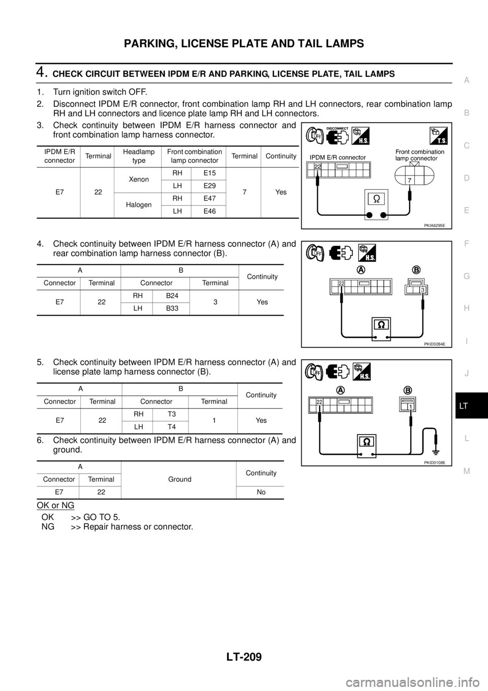
4. CHECK CIRCUIT BETWEEN IPDM E/R AND PARKING, LICENSE PLATE, TAIL LAMPS
1. Turn ignition switch OFF.
2. Disconnect IPDM E/R connector, front combination lamp RH and LH connectors, rear combination lamp
RH and LH connectors and licence plate lamp RH and LH connectors.
3. Check continuity between IPDM E/R harness connector and
front combination lamp harness connector.
4. Check continuity between IPDM E/R harness connector (A) and
rear combination lamp harness connector (B).
5. Check continuity between IPDM E/R harness connector (A) and
license plate lamp harness connector (B).
6. Check continuity between IPDM E/R harness connector (A) and
ground.
OK or NG
OK >> GO TO 5.
NG >> Repair harness or connector.
IPDM E/R
connectorTerminalHeadlamp
typeFront combination
lamp connectorTerminal Continuity
E7 22XenonRH E15
7 Yes LH E29
HalogenRH E47
LH E46
PKIA6295E
AB
Continuity
Connector Terminal Connector Terminal
E7 22RH B24
3Yes
LH B33
PKID0284E
AB
Continuity
Connector Terminal Connector Terminal
E7 22RH T3
1Yes
LH T4
A
GroundContinuity
Connector Terminal
E7 22 No
PKID0108E