Page 591 of 3502
INTEGRATED COLOR DISPLAY SYSTEM
AV-63
C
D
E
F
G
H
I
J
L
MA
B
AV
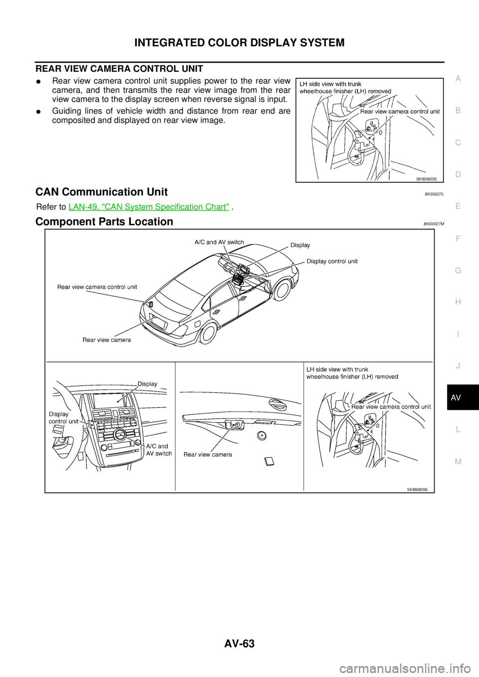
REAR VIEW CAMERA CONTROL UNIT
�Rear view camera control unit supplies power to the rear view
camera, and then transmits the rear view image from the rear
view camera to the display screen when reverse signal is input.
�Guiding lines of vehicle width and distance from rear end are
composited and displayed on rear view image.
CAN Communication UnitBKS0027L
Refer to LAN-49, "CAN System Specification Chart" .
Component Parts LocationBKS0027M
SKIB0803E
SKIB8809E
Page 605 of 3502

ItemSignal
input/
outputCondition
Reference valu")
INTEGRATED COLOR DISPLAY SYSTEM
AV-77
C
D
E
F
G
H
I
J
L
MA
B
AV
Terminals and Reference Value for Display Control UnitBKS0027R
Terminal
(Wire color)
ItemSignal
input/
outputCondition
Reference value
+–Ignition
switchOperation
1 (Y) Ground Battery power supply Input OFF — Battery voltage
2 (L/B) GroundPower supply
(Inverter) Output ON — Approx. 9 V
3 (B) Ground Ground — ON — Approx. 0 V
4 (L/Y) Ground Power supply (Signal) Output ON — Approx. 9 V
5 (P) Ground Ground (Inverter) — ON — Approx. 0 V
6 (G/W) Ground Reverse signal Input ONSelector lever in R position Approx. 12 V
Selector lever except in R
positionApprox. 0 V
7 (R/W) Ground Ground (Signal) — ON — Approx. 0 V
8 (BR/W) GroundCamera-connection
recognition signalInput ONConnected to rear view
camera control unit connec-
torApprox. 0 V
Not connected to rear view
camera control unit connec-
torApprox. 5 V
10 (V) Ground ACC power supply Input ACC — Battery voltage
12 (G) Ground Ignition signal Input ON — Battery voltage
14 (R/L) Ground Illumination signal Input ONLighting switch ON Approx. 12 V
Lighting switch OFF Approx. 0 V
16 (V/W) GroundVehicle speed signal
(8-pulse)Input ONWhen vehicle speed is
approx. 40 km/h (25 MPH)NOTE:
Maximum voltage may be 5 V
due to specifications (connected
units).
25 (L) — CAN-H — — — —
26 (P) — CAN-L — — — —
28 (BR) GroundCommunication
signal (+)Input/
OutputON —
29 — Shield — — — —
30 (Y) GroundCommunication
signal (–)Input/
OutputON —
PKIA1935E
SKIB7378E
SKIB7379E
Page 608 of 3502

ItemSignal
input/
outputCondition
Reference value
+–Ignition
switchOperation")
AV-80
INTEGRATED COLOR DISPLAY SYSTEM
Terminals and Reference Value for DisplayBKS0027S
Te r m i n a l
(Wire color)
ItemSignal
input/
outputCondition
Reference value
+–Ignition
switchOperation
1 (B) Ground Ground — ON — Approx. 0 V
2 (L/B) GroundPower supply
(Inverter) Input ON — Approx. 9 V
3 (L/Y) Ground Power supply (Signal) Input ON — Approx. 9 V
4 — Shield — — — —
6 (B) Ground RGB signal (G: green) Input ONStart DCU Confirmation
mode, and then display
color bar by selecting “Dis-
play Color Spectrum Bar”
on Display Diagnosis
screen
7 (W) Ground Ground (RGB) — ON — Approx. 0 V
8 (B) GroundHorizontal
synchronizing (HP)
signalOutput ON —
9 (G) Ground RGB area (YS) signal Input ONWhen displaying RGB
imageApprox. 5 V
When displaying rear view
imageApprox. 0 V
11 (BR) GroundCommunication signal
(DCU-DSP)Input ON —
13 (P) Ground Ground (Inverter) — ON — Approx. 0 V
14 (R/W) Ground Ground (Signal) — ON — Approx. 0 V
15 (W) GroundRear view image
signalInput ONSet the selector lever in R
position, and then display
the rear view image
17 (R) Ground RGB signal (R: red) Input ONStart DCU Confirmation
mode, and then display
color bar by selecting “Dis-
play Color Spectrum Bar”
on Display Diagnosis
screen
SKIB7770E
SKIB3601E
SKIB3607E
SKIB3608E
SKIB7769E
Page 610 of 3502
AV-82
INTEGRATED COLOR DISPLAY SYSTEM
Terminals and Reference Value for A/C and AV SwitchBKS0027T
Te r m i n a l
(Wire color)
ItemSignal
input/
outputCondition
Reference value
+–Ignition
switchOperation
1 (G/B) 3 (B/W)Remote control signal
AInput ONPress and hold MODE
switchApprox. 0 V
Press and hold SEEK
DOWN switchApprox. 1.7 V
Press and hold VOL DOWN
switchApprox. 3.3 V
Except for above Approx. 5 V
2 (R) 3 (B/W)Remote control signal
BInput ONPress and hold POWER
switchApprox. 0 V
Press and hold SEEK UP
switchApprox. 1.7 V
Press and hold VOL UP
switchApprox. 3.3 V
Except for above Approx. 5 V
3 (B/W) GroundRemote control
ground— ON — Approx. 0 V
7 (V) Ground ACC power supply Input ACC — Battery voltage
11 (Y) GroundCommunication
signal (–)Input/
OutputON —
12 (BR) GroundCommunication
signal (+)Input/
OutputON —
13 (B) Ground Ground — ON — Approx. 0 V
14 — Shield — — — —
SKIB7379E
SKIB7378E
Page 611 of 3502

ItemSignal
input/
outputCondition
Refer")
INTEGRATED COLOR DISPLAY SYSTEM
AV-83
C
D
E
F
G
H
I
J
L
MA
B
AV
Terminals and Reference Value for Rear View Camera Control UnitBKS0027U
Terminal
(Wire color)
ItemSignal
input/
outputCondition
Reference value
+–Ignition
switchOperation
1 (Y) Ground Battery power supply Input OFF — Battery voltage
2 (V) Ground ACC power supply Input ACC — Battery voltage
3 (B) Ground Ground — ON — Approx. 0 V
4 (G/W) Ground Reverse signal Input ONSelector lever in R position Approx. 12 V
Other than selector lever in
R positionApprox. 0 V
5 (BR/W) GroundCamera-connection
recognition signalOutput ON — Approx. 0 V
6 (O) —Data transmit/receive
signal—— — —
8 (P) Ground Camera power supply Output ONSet the selector lever in R
position, and then display
the rear view imageApprox. 6 V
9 — Shield — — — —
10 (W) GroundRear view image
signalInput ONSet the selector lever in R
position, and then display
the rear view image
11 — Shield — — — —
12 (BR) GroundRear view image
signalOutput ONSet the selector lever in R
position, and then display
the rear view image
SKIB3608E
SKIB3608E
Page 616 of 3502

AV-88
INTEGRATED COLOR DISPLAY SYSTEM
SELF-DIAGNOSIS RESULT
Check the applicable display in the following table, and then repair the malfunctioning parts.
Quick Reference Table
Self-diagnosis result screen Possible cause Action to take
Display control unit malfunction is
detected.Replace display control unit.
Malfunction is detected on communi-
cation signal between display control
unit and display.1. Check communication circuit between
display control unit and display.
2. Check communication signal between
display control unit and display.
3. If the results from the above checkup
show no malfunction, replace either
display control unit or display, and then
start self-diagnosis.
4. If self-diagnosis results still show any
malfunction, replace the other unit.
�Audio unit power supply circuit mal-
function is detected.
�Malfunction is detected on commu-
nication signal between display con-
trol unit and audio unit.1. Check audio unit power supply circuit.
2. Check communication circuit between
display control unit and audio unit.
3. Check communication signal between
display control unit and audio unit.
4. If the results from the above checkup
show no malfunction, replace either
display control unit or audio unit, and
then start self-diagnosis.
5. If self-diagnosis results still show any
malfunction, replace the other unit.
�CD auto changer power supply cir-
cuit malfunction is detected.
�Malfunction is detected on commu-
nication signal between audio unit
and CD auto changer.1. Check CD auto changer power supply
circuit.
2. Check communication circuit between
audio unit and CD auto changer.
3. Check communication signal between
audio unit and CD auto changer.
4. If the results from the above checkup
show no malfunction, replace either
audio unit or CD auto changer, and
then start self-diagnosis.
5. If self-diagnosis results still show any
malfunction, replace the other unit.
SKIB8827E
SKIB8828E
SKIB8829E
SKIB8830E
Page 619 of 3502

INTEGRATED COLOR DISPLAY SYSTEM
AV-91
C
D
E
F
G
H
I
J
L
MA
B
AV
Diagnosis by History of Error
When having a difficulty on the investigation of cause due to multiple errors with a reproducible malfunction,
turn ON the ignition switch from OFF mode after making a memo of the item and number of time (or delete
“History of Error”). Check “History of Error” again after the malfunction was reproduced, and then perform
diagnosis focusing on the item of which number of time increased.
Error item Possible cause Action to take
DCU malfunctionDisplay control unit malfunction is
detected.Replace display control unit.
Display Connect Error
�Display power supply and ground
circuit malfunction is detected.
�Malfunction is detected on commu-
nication signal between display con-
trol unit and display.1. Delete the “History of Error”, and turn
OFF ignition switch.
2. Turn ON ignition switch, and make sure
of the “History of Error”.
3. If the error item listed left is displayed
again, GO TO 4. If the error item is not
displayed, end the diagnosis. (This is
not a malfunction.)
4. Check display power supply and
ground circuit.
5. Check communication circuit between
display control unit and display.
6. Check communication signal between
display control unit and display.
7. If the results from the above checkup
show no malfunction, replace either
display control unit or display, and then
start self-diagnosis.
8. If self-diagnosis results still show any
malfunction, replace the other unit.
Page 620 of 3502

AV-92
INTEGRATED COLOR DISPLAY SYSTEM
Software Version
Software version of each unit is displayed.
HVAC
Self-diagnosis of air conditioner system is performed. Refer to AT C - 4 6 , "Self-diagnosis Function" .
Audio Connect Error
�Audio unit power supply circuit mal-
function is detected.
�Malfunction is detected on commu-
nication signal between display con-
trol unit and audio unit.1. Start self-diagnosis, and make sure of
the result.
2. If any error is found, GO TO 3. If any
error is not found, delete the “History of
Error” and end the diagnosis. (This is
not a malfunction.)
3. Check audio unit power supply circuit.
4. Check communication circuit between
display control unit and audio unit.
5. Check communication signal between
display control unit and audio unit.
6. If the results from the above checkup
show no malfunction, replace either
display control unit or audio unit, and
then start self-diagnosis.
7. If self-diagnosis results still show any
malfunction, replace the other unit.
SW Error
�A/C and AV switch power supply
and ground circuit malfunction is
detected.
�Malfunction is detected on commu-
nication signal between display con-
trol unit and A/C and AV switch.1. Delete the “History of Error”, and turn
OFF ignition switch.
2. Turn ON ignition switch, and make sure
of the “History of Error”.
3. If the error item listed left is displayed
again, GO TO 4. If the error item is not
displayed, end the diagnosis. (This is
not a malfunction.)
4. Check A/C and AV switch power supply
and ground circuit.
5. Check communication circuit between
display control unit and A/C and AV
switch.
6. If the results from the above checkup
show no malfunction, replace either
display control unit or A/C and AV
switch, and then start self-diagnosis.
7. If self-diagnosis results still show any
malfunction, replace the other unit. Error item Possible cause Action to take

ItemSignal
input/
outputCondition
Reference value
+–Ignition
switchO")