Page 2749 of 3189
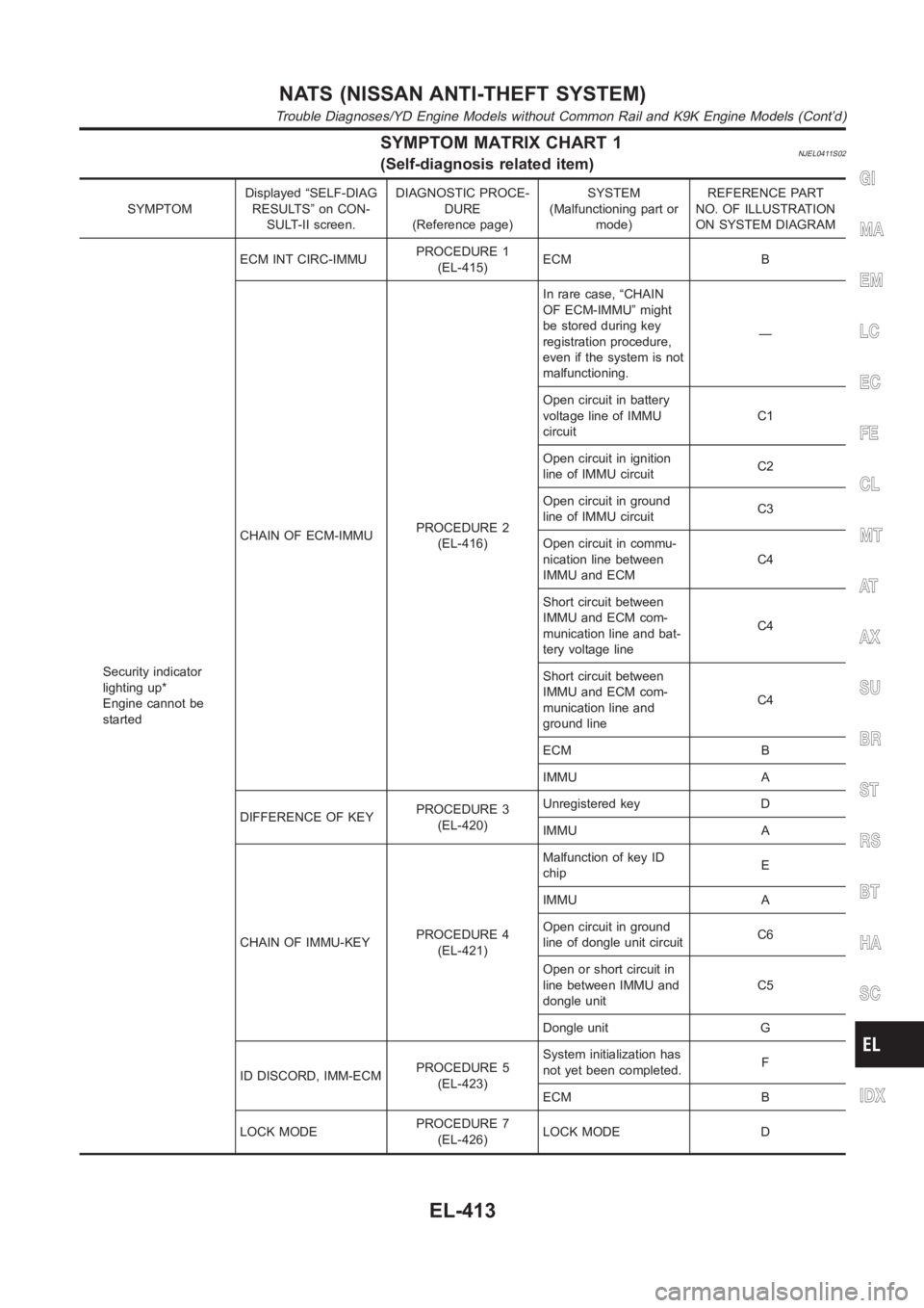
SYMPTOM MATRIX CHART 1NJEL0411S02(Self-diagnosis related item)
SYMPTOMDisplayed “SELF-DIAG
RESULTS” on CON-
SULT-II screen.DIAGNOSTIC PROCE-
DURE
(Reference page)SYSTEM
(Malfunctioning part or
mode)REFERENCE PART
NO. OF ILLUSTRATION
ON SYSTEM DIAGRAM
Security indicator
lighting up*
Engine cannot be
startedECM INT CIRC-IMMUPROCEDURE 1
(EL-415)ECM B
CHAIN OF ECM-IMMUPROCEDURE 2
(EL-416)In rare case, “CHAIN
OF ECM-IMMU” might
be stored during key
registration procedure,
even if the system is not
malfunctioning.—
Open circuit in battery
voltage line of IMMU
circuitC1
Open circuit in ignition
line of IMMU circuitC2
Open circuit in ground
line of IMMU circuitC3
Open circuit in commu-
nication line between
IMMU and ECMC4
Short circuit between
IMMU and ECM com-
munication line and bat-
tery voltage lineC4
Short circuit between
IMMU and ECM com-
munication line and
ground lineC4
ECM B
IMMU A
DIFFERENCE OF KEYPROCEDURE 3
(EL-420)Unregistered key D
IMMU A
CHAIN OF IMMU-KEYPROCEDURE 4
(EL-421)Malfunction of key ID
chipE
IMMU A
Open circuit in ground
line of dongle unit circuitC6
Open or short circuit in
line between IMMU and
dongle unitC5
Dongle unit G
ID DISCORD, IMM-ECMPROCEDURE 5
(EL-423)System initialization has
not yet been completed.F
ECM B
LOCK MODEPROCEDURE 7
(EL-426)LOCK MODE D
GI
MA
EM
LC
EC
FE
CL
MT
AT
AX
SU
BR
ST
RS
BT
HA
SC
IDX
NATS (NISSAN ANTI-THEFT SYSTEM)
Trouble Diagnoses/YD Engine Models without Common Rail and K9K Engine Models (Cont’d)
EL-413
Page 2754 of 3189
5 CHECK COMMUNICATION LINE OPEN CIRCUIT
1. Disconnect ECM connector.
2. Check harness continuity between ECM terminal 116 (Gasoline engine) or410 (Diesel engine) and IMMU terminal 1.
SEL305WB
OK or NG
OK GO TO 6.
NG Repair harness or connector.
Ref. part No. C4
6 CHECK COMMUNICATION LINE BATTERY SHORT CIRCUIT
1. Turn ignition ON.
2. Check voltage between ECM terminal 116 (Gasoline engine) or 410 (Dieselengine) or IMMU terminal 1 and ground.
SEL306WB
OK or NG
OK GO TO 7.
NG Communication line is short-circuited with battery voltage line or ignition switch ON line.
Repair harness or connectors.
Ref. part No. C4
NATS (NISSAN ANTI-THEFT SYSTEM)
Trouble Diagnoses/YD Engine Models without Common Rail and K9K Engine Models (Cont’d)
EL-418
Page 2776 of 3189
SKIA1400E
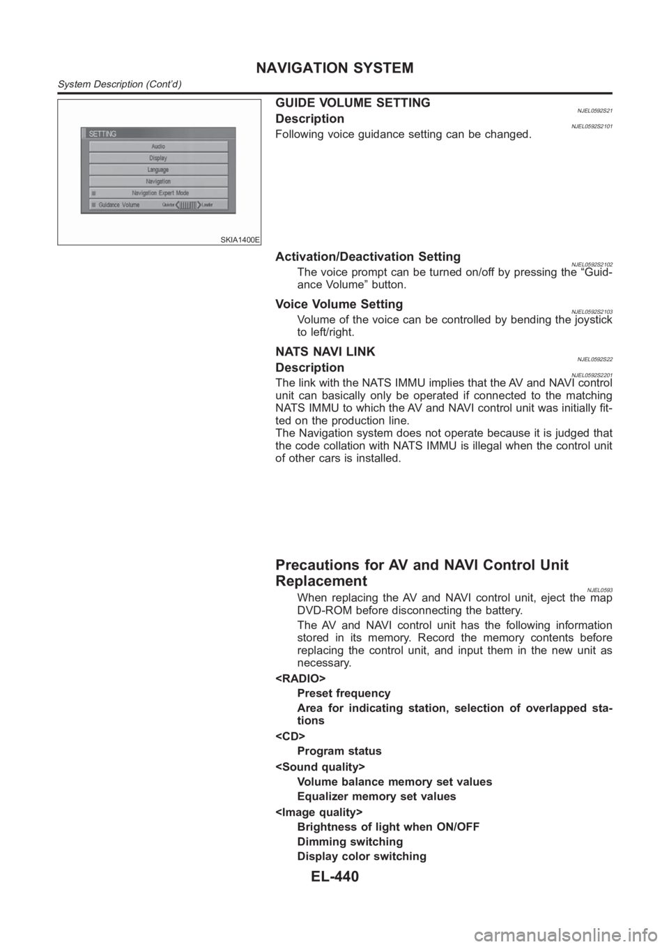
GUIDE VOLUME SETTINGNJEL0592S21DescriptionNJEL0592S2101Following voice guidance setting can be changed.
Activation/Deactivation SettingNJEL0592S2102The voice prompt can be turned on/off by pressing the “Guid-
ance Volume” button.
Voice Volume SettingNJEL0592S2103Volume of the voice can be controlled by bending the joystick
to left/right.
NATS NAVI LINKNJEL0592S22DescriptionNJEL0592S2201The link with the NATS IMMU implies that the AV and NAVI control
unit can basically only be operated if connected to the matching
NATS IMMU to which the AV and NAVI control unit was initially fit-
ted on the production line.
The Navigation system does not operate because it is judged that
the code collation with NATS IMMU is illegal when the control unit
of other cars is installed.
Precautions for AV and NAVI Control Unit
Replacement
NJEL0593When replacing the AV and NAVI control unit, eject the map
DVD-ROM before disconnecting the battery.
The AV and NAVI control unit has the following information
stored in its memory. Record the memory contents before
replacing the control unit, and input them in the new unit as
necessary.
Preset frequency
Area for indicating station, selection of overlapped sta-
tions
Program status
Volume balance memory set values
Equalizer memory set values
Brightness of light when ON/OFF
Dimming switching
Display color switching
NAVIGATION SYSTEM
System Description (Cont’d)
EL-440
Page 2777 of 3189
Latest status (map screen/bird view , reduced scale, rota-
tion angle of map screen, route guide ON/OFF, track
ON/OFF, etc.)
Current position
Destination, passing point 1 - 5
Registered places, their names, etc.
NOTE:
Only removing the battery does not erase the memory.
Component Parts LocationNJEL0594For details, refer to “ELECTRICAL UNIT LOCATION” (EL-543) and
“HARNESS LAYOUT” (EL-550).
Location of AntennaNJEL0595Refer to EL-214, “Location of Antenna”.
GI
MA
EM
LC
EC
FE
CL
MT
AT
AX
SU
BR
ST
RS
BT
HA
SC
IDX
NAVIGATION SYSTEM
Precautions for AV and NAVI Control Unit Replacement (Cont’d)
EL-441
Page 2786 of 3189
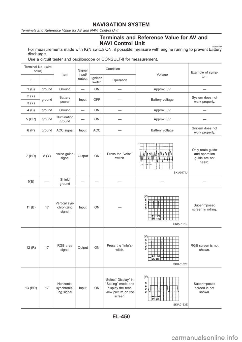
Terminals and Reference Value for AV and
NAVI Control Unit
NJEL0599For measurements made with IGN switch ON, if possible, measure with enginerunning to prevent battery
discharge.
Use a circuit tester and oscilloscope or CONSULT-ll for measurement.
Terminal No. (wire
color)
ItemSignal
input/
outputCondition
VoltageExample of symp-
tom
+−Ignition
switchOperation
1 (B) ground Ground — ON — Approx. 0V —
2 (Y)
groundBattery
powerInput OFF — Battery voltageSystem does not
work properly.
3 (Y)
4 (B) ground Ground — ON — Approx. 0V —
5 (BR) groundIllumination
ground— ON — Approx. 0V —
6 (P) ground ACC signal Input ACC — Battery voltageSystem does not
work properly.
7 (BR) 8 (Y)voice guide
signalOutput ONPress the “voice”
switch.
SKIA0171J
Only route guide
and operation
guide are not
heard.
9(B) —Shield
ground—— — — —
11 (B) 17Vertical syn-
chronizing
signalInput ON —
SKIA0161E
Superimposed
screen is rolling.
12 (R) 17RGB area
signalOutput ONPress the “info”s-
witch.
SKIA0162E
RGB screen is not
shown.
13 (BR) 17Horizontal
synchroniz-
ing signalInput ONSelect“ Display” in
“Setting” mode and
display the rear-
view picture on the
screen.
SKIA0163E
Superimposed
screen is not
shown.
NAVIGATION SYSTEM
Terminals and Reference Value for AV and NAVI Control Unit
EL-450
Page 2787 of 3189
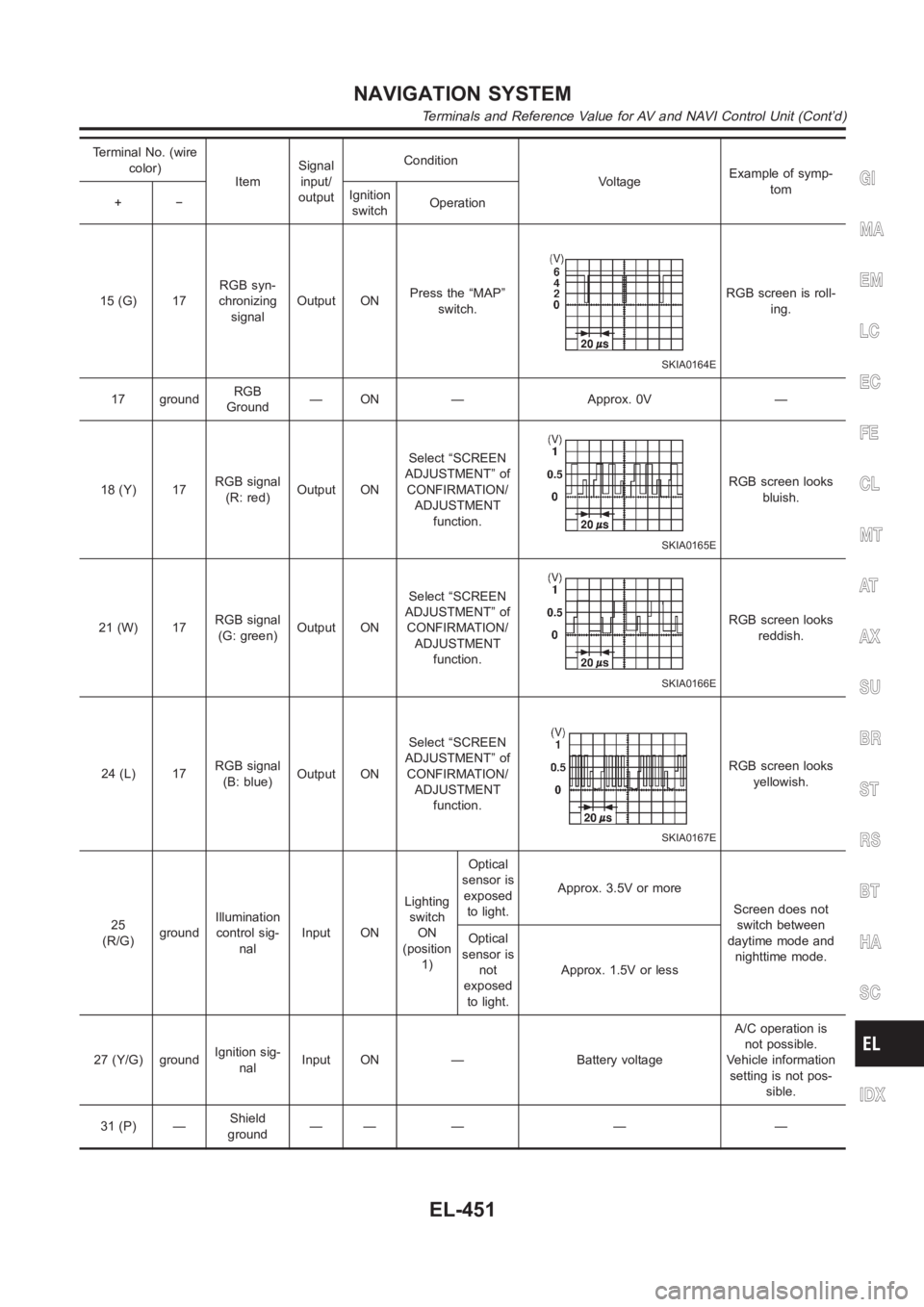
Terminal No. (wire
color)
ItemSignal
input/
outputCondition
VoltageExample of symp-
tom
+−Ignition
switchOperation
15 (G) 17RGB syn-
chronizing
signalOutput ONPress the “MAP”
switch.
SKIA0164E
RGB screen is roll-
ing.
17 groundRGB
Ground— ON — Approx. 0V —
18 (Y) 17RGB signal
(R: red)Output ONSelect “SCREEN
ADJUSTMENT” of
CONFIRMATION/
ADJUSTMENT
function.
SKIA0165E
RGB screen looks
bluish.
21 (W) 17RGB signal
(G: green)Output ONSelect “SCREEN
ADJUSTMENT” of
CONFIRMATION/
ADJUSTMENT
function.
SKIA0166E
RGB screen looks
reddish.
24 (L) 17RGB signal
(B: blue)Output ONSelect “SCREEN
ADJUSTMENT” of
CONFIRMATION/
ADJUSTMENT
function.
SKIA0167E
RGB screen looks
yellowish.
25
(R/G)groundIllumination
control sig-
nalInput ONLighting
switch
ON
(position
1)Optical
sensor is
exposed
to light.Approx. 3.5V or more
Screen does not
switch between
daytime mode and
nighttime mode. Optical
sensor is
not
exposed
to light.Approx. 1.5V or less
27 (Y/G) groundIgnition sig-
nalInput ON — Battery voltageA/C operation is
not possible.
Vehicle information
setting is not pos-
sible.
31 (P) —Shield
ground—— — — —
GI
MA
EM
LC
EC
FE
CL
MT
AT
AX
SU
BR
ST
RS
BT
HA
SC
IDX
NAVIGATION SYSTEM
Terminals and Reference Value for AV and NAVI Control Unit (Cont’d)
EL-451
Page 2788 of 3189
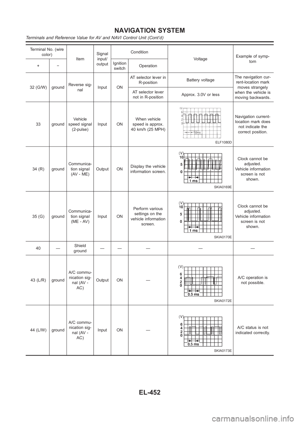
Terminal No. (wire
color)
ItemSignal
input/
outputCondition
VoltageExample of symp-
tom
+−Ignition
switchOperation
32 (G/W) groundReverse sig-
nalInput ONAT selector lever in
R-positionBattery voltageThe navigation cur-
rent-location mark
moves strangely
when the vehicle is
moving backwards. AT selector lever
not in R-positionApprox. 3.0V or less
33 groundVehicle
speed signal
(2-pulse)Input ONWhen vehicle
speed is approx.
40 km/h (25 MPH)
ELF1080D
Navigation current-
location mark does
not indicate the
correct position.
34 (R) groundCommunica-
tion signal
(AV - ME)Output ONDisplay the vehicle
information screen.
SKIA0169E
Clock cannot be
adjusted.
Vehicle information
screen is not
shown.
35 (G) groundCommunica-
tion signal
(ME - AV)Input ONPerform various
settings on the
vehicle information
screen.
SKIA0170E
Clock cannot be
adjusted.
Vehicle information
screen is not
shown.
40 —Shield
ground—— — — —
43 (L/R) groundA/C commu-
nication sig-
nal (AV -
AC)Output ON —
SKIA0172E
A/C operation is
not possible.
44 (L/W) groundA/C commu-
nication sig-
nal (AV -
AC)Input ON —
SKIA0173E
A/C status is not
indicated correctly.
NAVIGATION SYSTEM
Terminals and Reference Value for AV and NAVI Control Unit (Cont’d)
EL-452
Page 2791 of 3189
Terminal No.
(wire color)
ItemSignal
input/
outputCondition
VoltageExample of
symptom
+−Ignition
switchOperation
8(R) 4RGB area
signalInput ON Press the “info” switch.
SKIA0162E
RGB screen is
not shown.
12
(W)groundCommunica-
tion signal
(-)Input/
outputON —
SKIA0176E
System does not
work properly.
13 (B) groundCommunica-
tion signal
(+)Input/
outputON —
SKIA0175E
System does not
work properly.
14 —Shield
ground—— — — —
19 (P) ground ACC signal Input ACC — Battery voltageScreen is not
shown.
21 (Y)
groundBattery
powerInput OFF — Battery voltageScreen is not
shown.
23 (Y)
22 (B) ground Ground — ON — Approx. 0V —
24 (B) ground Ground — ON — Approx. 0V —
GI
MA
EM
LC
EC
FE
CL
MT
AT
AX
SU
BR
ST
RS
BT
HA
SC
IDX
NAVIGATION SYSTEM
Terminals and Reference Value for Display Unit (Cont’d)
EL-455