Page 2417 of 3189
INTERIOR ROOM LAMP TIMER OPERATIONNJEL0435S03When interior room lamp switch is in the “DOOR” position, the smart entrance control unit keeps the interior
room lamp illuminated for about 30 seconds when:
unlock signal is supplied from driver’s door lock/unlock switch while alldoors are closed
unlock signal is supplied from remote controller while all doors are closed and key is out of the ignition
key cylinder,
key is removed from ignition key cylinder while all doors are closed
driver’s door is opened and then closed while key is out of the ignition key cylinder. (However, if the driv-
er’s door is closed with the key inserted in the ignition key cylinder afterthe driver’s door is opened with
the key removed, the timer is operated
The timer is canceled when:
driver’s door is locked,
driver’s door is opened, or
ignition switch is turned ON.
ON-OFF CONTROLNJEL0435S04When the driver side door, front passenger door, rear LH or RH door is opened, the interior room lamp turns
on while the interior room lamp switch is in the “DOOR” position.
BATTERY SAVERNJEL0435S11The interior room lamp is turned OFF automatically with the lamp switch in the “DOOR” position after about
30 minutes, if the lamp remains lit by the door switch open signal.
GI
MA
EM
LC
EC
FE
CL
MT
AT
AX
SU
BR
ST
RS
BT
HA
SC
IDX
INTERIOR ROOM LAMP
System Description/QG and YD Engine Models with Common Rail (Cont’d)
EL-81
Page 2419 of 3189
driver’s door is locked,
driver’s door is opened, or
ignition switch is turned ON.
ON-OFF CONTROLNJEL0548S04When the driver side door, front passenger door, rear LH or RH door is opened, the interior room lamp turns
on while the interior room lamp switch is in the “DOOR” position.
BATTERY SAVERNJEL0548S05The interior room lamp is turned OFF automatically with the lamp switch in the “DOOR” position after about
30 minutes, if the lamp remains lit by the door switch open signal.
GI
MA
EM
LC
EC
FE
CL
MT
AT
AX
SU
BR
ST
RS
BT
HA
SC
IDX
INTERIOR ROOM LAMP
System Description/YD Engine Models without Common Rail and K9K Engine Models (Cont’d)
EL-83
Page 2446 of 3189
Component Parts and Harness Connector
Location
NJEL0441For details, refer to “ELECTRICAL UNIT LOCATION” (EL-543) and
“HARNESS LAYOUT” (EL-550).
System DescriptionNJEL0442UNIFIED CONTROL METERNJEL0442S01Speedometer, odo/trip meter, tachometer, fuel gauge and water temperature gauge are controlled totally
by control unit built-in combination meter.
Digital meter is adopted for odo/trip meter.*
*The record of the odo meter is kept even if the battery cable is disconnected. The record of the trip meter
is erased when the battery cable is disconnected.
Odo/trip meter segment can be checked in diagnosis mode.
Meter/gauge can be checked in diagnosis mode.
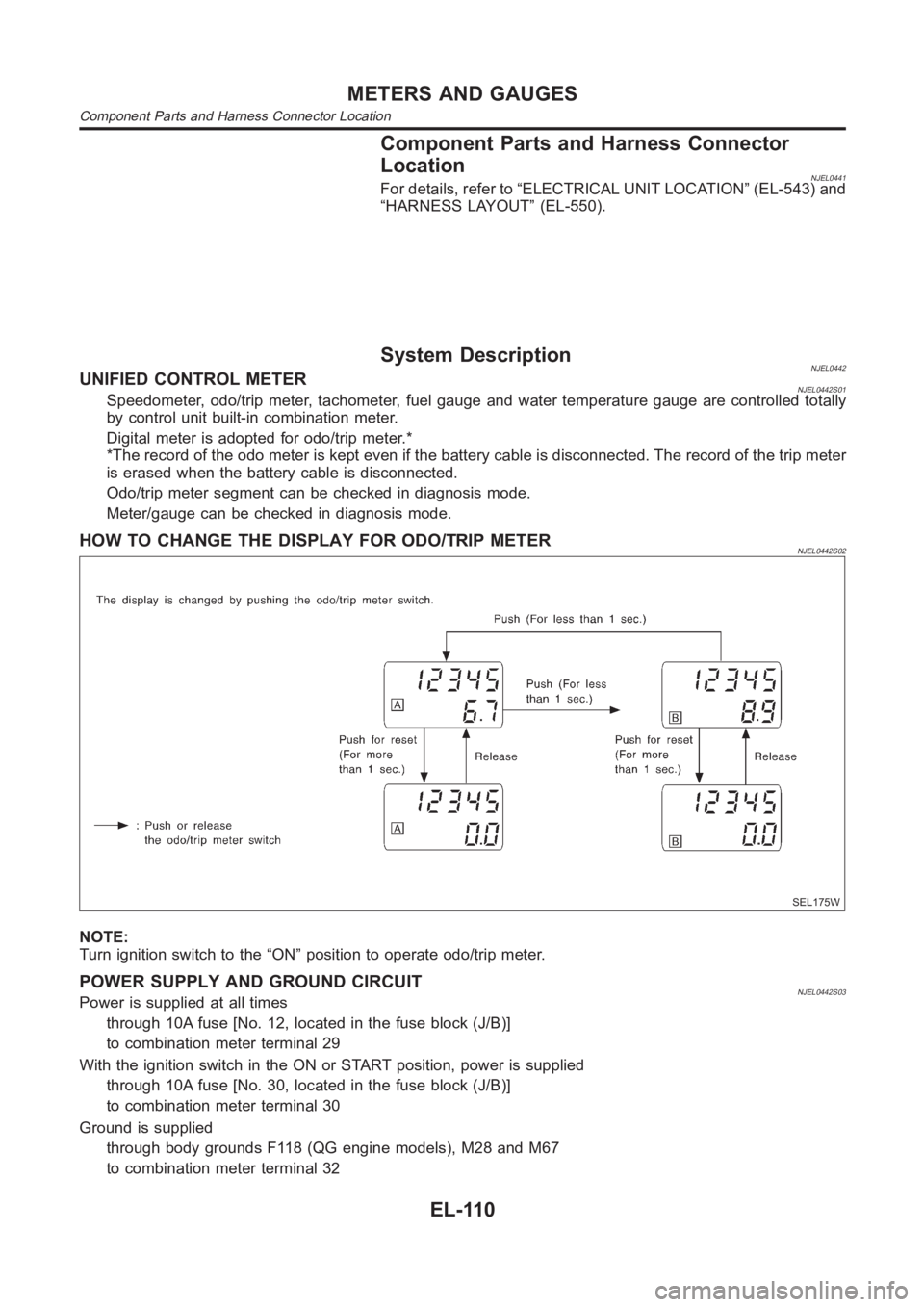
HOW TO CHANGE THE DISPLAY FOR ODO/TRIP METERNJEL0442S02
SEL175W
NOTE:
Turn ignition switch to the “ON” position to operate odo/trip meter.
POWER SUPPLY AND GROUND CIRCUITNJEL0442S03Power is supplied at all times
through 10A fuse [No. 12, located in the fuse block (J/B)]
to combination meter terminal 29
With the ignition switch in the ON or START position, power is supplied
through 10A fuse [No. 30, located in the fuse block (J/B)]
to combination meter terminal 30
Ground is supplied
through body grounds F118 (QG engine models), M28 and M67
to combination meter terminal 32
METERS AND GAUGES
Component Parts and Harness Connector Location
EL-110
Page 2458 of 3189
YEL813D
POWER SUPPLY AND GROUND CIRCUIT CHECK=NJEL0448S03Power Supply Circuit CheckNJEL0448S0301
Terminals Ignition switch position
(+) (−) OFF ACC ON
29 GroundBattery
voltageBattery
voltageBattery
voltage
30 Ground 0V 0VBattery
voltage
64 Ground 0VBattery
voltageBattery
voltage
If NG, check the following.
10A fuse [No. 12, located in fuse block (J/B)]
10A fuse [No. 30, located in fuse block (J/B)]
10A fuse [No. 1, located in fuse block (J/B)]
Harness for open or short between fuse and combination
meter
YEL814D
Ground Circuit CheckNJEL0448S0302
Terminals Continuity
32 - Ground Yes
METERS AND GAUGES
Trouble Diagnoses (Cont’d)
EL-122
Page 2481 of 3189
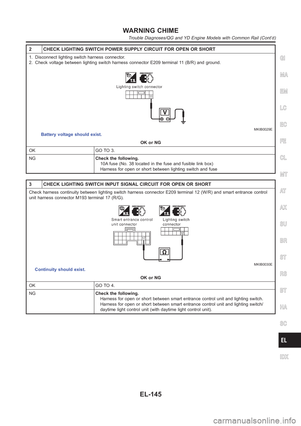
2 CHECK LIGHTING SWITCH POWER SUPPLY CIRCUIT FOR OPEN OR SHORT
1. Disconnect lighting switch harness connector.
2. Check voltage between lighting switch harness connector E209 terminal11 (B/R) and ground.
MKIB0029E
Battery voltage should exist.
OK or NG
OK GO TO 3.
NGCheck the following.
10A fuse (No. 38 located in the fuse and fusible link box)
Harness for open or short between lighting switch and fuse
3 CHECK LIGHTING SWITCH INPUT SIGNAL CIRCUIT FOR OPEN OR SHORT
Check harness continuity between lighting switch harness connector E209terminal 12 (W/R) and smart entrance control
unit harness connector M193 terminal 17 (R/G).
MKIB0030E
Continuity should exist.
OK or NG
OK GO TO 4.
NGCheck the following.
Harness for open or short between smart entrance control unit and lightingswitch.
Harness for open or short between smart entrance control unit and lightingswitch/
daytime light control unit (with daytime light control unit).
GI
MA
EM
LC
EC
FE
CL
MT
AT
AX
SU
BR
ST
RS
BT
HA
SC
IDX
WARNING CHIME
Trouble Diagnoses/QG and YD Engine Models with Common Rail (Cont’d)
EL-145
Page 2484 of 3189
2 CHECK KEY SWITCH POWER SUPPLY CIRCUIT FOR OPEN OR SHORT
1. Disconnect key switch harness connector.
2. Check voltage between key switch harness connector E173 terminal 1 (R) and ground.
MKIB0032E
Battery voltage should exist.
OK or NG
OK GO TO 3.
NGCheck the following.
10A fuse [No. 12 located in fuse block (J/B)]
Harness for open or short between key switch and fuse
3 CHECK KEY SWITCH INPUT SIGNAL CIRCUIT FOR OPEN OR SHORT
Check harness continuity between key switch harness connector E173 terminal 2 (L/W) and smart entrance control unit
harness connector M193 terminal 5 (L/W).
MKIB0033E
Continuity should exist.
OK or NG
OK GO TO 4.
NG Repair or replace harness.
WARNING CHIME
Trouble Diagnoses/QG and YD Engine Models with Common Rail (Cont’d)
EL-148
Page 2515 of 3189
Trouble Diagnoses/QG and YD Engine Models
with Common Rail
NJEL0553TERMINALS AND REFERENCE VALUE FOR SMART
ENTRANCE CONTROL UNIT
NJEL0553S01
TERMINALWIRE
COLORITEM CONDITION DATA (DC)
22 L/YMultifunction switch (Rear window
defogger switch) signalMultifunction switch (Rear window defogger
switch) ON0V
Multifunction switch (Rear window defogger
switch) OFFBattery voltage
29 Y/G IGN power supply — Battery voltage
31 WRear window defogger relay control sig-
nalMultifunction switch (Rear window defogger
switch) ONBattery voltage
Multifunction switch (Rear window defogger
switch) OFF0V
53 B Ground — 0V
56 R/B BAT power supply — Battery voltage
TERMINALS AND REFERENCE VALUE FOR
MULTIFUNCTION SWITCH (REAR WINDOW DEFOGGER
SWITCH)
NJEL0553S02
TERMINALWIRE
COLORITEM CONDITION DATA (DC)
1 B Ground — 0V
9 L/Y Rear window defogger switch signal Rear window defogger switch ON Battery voltage
10 L/R Rear window defogger indicator signal Rear window defogger switch ON Battery voltage
PRELIMINARY CHECKNJEL0553S03First perform the “SELF-DIAG RESULTS” in “SMART ENTRANCE”
with CONSULT-II, when perform the each trouble diagnosis.
GI
MA
EM
LC
EC
FE
CL
MT
AT
AX
SU
BR
ST
RS
BT
HA
SC
IDX
REAR WINDOW DEFOGGER
Trouble Diagnoses/QG and YD Engine Models with Common Rail
EL-179
Page 2529 of 3189
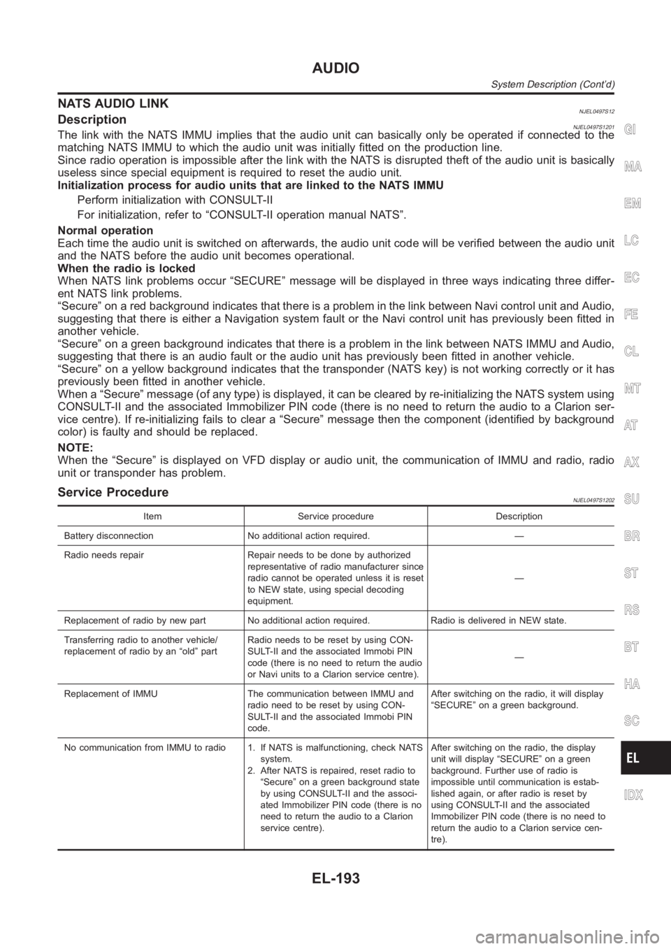
NATS AUDIO LINKNJEL0497S12DescriptionNJEL0497S1201The link with the NATS IMMU implies that the audio unit can basically only beoperated if connected to the
matching NATS IMMU to which the audio unit was initially fitted on the production line.
Since radio operation is impossible after the link with the NATS is disrupted theft of the audio unit is basically
useless since special equipment is required to reset the audio unit.
Initialization process for audio units that are linked to the NATS IMMU
Perform initialization with CONSULT-II
For initialization, refer to “CONSULT-II operation manual NATS”.
Normal operation
Each time the audio unit is switched on afterwards, the audio unit code willbe verified between the audio unit
and the NATS before the audio unit becomes operational.
When the radio is locked
When NATS link problems occur “SECURE” message will be displayed in three ways indicating three differ-
ent NATS link problems.
“Secure” on a red background indicates that there is a problem in the link between Navi control unit and Audio,
suggesting that there is either a Navigation system fault or the Navi control unit has previously been fitted in
another vehicle.
“Secure” on a green background indicates that there is a problem in the linkbetween NATS IMMU and Audio,
suggesting that there is an audio fault or the audio unit has previously been fitted in another vehicle.
“Secure” on a yellow background indicates that the transponder (NATS key)is not working correctly or it has
previously been fitted in another vehicle.
When a “Secure” message (of any type) is displayed, it can be cleared by re-initializing the NATS system using
CONSULT-II and the associated Immobilizer PIN code (there is no need to return the audio to a Clarion ser-
vice centre). If re-initializing fails to clear a “Secure” message then the component (identified by background
color) is faulty and should be replaced.
NOTE:
When the “Secure” is displayed on VFD display or audio unit, the communication of IMMU and radio, radio
unit or transponder has problem.
Service ProcedureNJEL0497S1202
Item Service procedure Description
Battery disconnection No additional action required. —
Radio needs repair Repair needs to be done by authorized
representative of radio manufacturer since
radio cannot be operated unless it is reset
to NEW state, using special decoding
equipment.—
Replacement of radio by new part No additional action required. Radio is delivered in NEW state.
Transferring radio to another vehicle/
replacement of radio by an “old” partRadio needs to be reset by using CON-
SULT-II and the associated Immobi PIN
code (there is no need to return the audio
or Navi units to a Clarion service centre).—
Replacement of IMMU The communication between IMMU and
radio need to be reset by using CON-
SULT-II and the associated Immobi PIN
code.After switching on the radio, it will display
“SECURE” on a green background.
No communication from IMMU to radio 1. If NATS is malfunctioning, check NATS
system.
2. After NATS is repaired, reset radio to
“Secure” on a green background state
by using CONSULT-II and the associ-
ated Immobilizer PIN code (there is no
need to return the audio to a Clarion
service centre).After switching on the radio, the display
unit will display “SECURE” on a green
background. Further use of radio is
impossible until communication is estab-
lished again, or after radio is reset by
using CONSULT-II and the associated
Immobilizer PIN code (there is no need to
return the audio to a Clarion service cen-
tre).
GI
MA
EM
LC
EC
FE
CL
MT
AT
AX
SU
BR
ST
RS
BT
HA
SC
IDX
AUDIO
System Description (Cont’d)
EL-193