Page 1849 of 3189
LINE PRESSURE SOLENOID VALVE
AT-393
[ALL]
D
E
F
G
H
I
J
K
L
MA
B
AT
Component InspectionECS007SM
LINE PRESSURE SOLENOID VALVE
●For removal, refer to AT-406, "Control Valve Assembly and Accumulators" .
Resistance Check
●Check resistance between two terminals.
Operation Check
●Check solenoid valve by listening for its operating sound while
applying battery voltage to the terminal and ground.
Solenoid valve Terminal No.Resistance
(Approx.)
Line pressure
solenoid valve4 Ground 2.5 - 5Ω
SAT898JA
SAT899JA
Page 1856 of 3189
![NISSAN ALMERA N16 2003 Electronic Repair Manual AT-400
[ALL]
A/T SHIFT LOCK SYSTEM
Diagnostic Procedure
ECS007SV
SYMPTOM 1:
●Selector lever cannot be moved from “P” position with key in ON position and brake pedal
applied.
●Selec NISSAN ALMERA N16 2003 Electronic Repair Manual AT-400
[ALL]
A/T SHIFT LOCK SYSTEM
Diagnostic Procedure
ECS007SV
SYMPTOM 1:
●Selector lever cannot be moved from “P” position with key in ON position and brake pedal
applied.
●Selec](/manual-img/5/57350/w960_57350-1855.png)
AT-400
[ALL]
A/T SHIFT LOCK SYSTEM
Diagnostic Procedure
ECS007SV
SYMPTOM 1:
●Selector lever cannot be moved from “P” position with key in ON position and brake pedal
applied.
●Selector lever can be moved from “P” position with key in ON position and brake pedal released.
●Selector lever can be moved from “P” position when key is removed from key cylinder.
SYMPTOM 2:
Ignition key cannot be removed when selector lever is set to “P” position. It can be removed when
selector lever is set to any position except “P”.
1. CHECK KEY INTERLOCK CABLE
Check key interlock cable for damage.
OK or NG
OK >> GO TO 2
NG >> Repair key interlock cable. Refer to AT- 4 0 4 , "
KEY INTERLOCK CABLE" .
2. CHECK SELECTOR LEVER POSITION
Check selector lever position for damage.
OK or NG
OK >> GO TO 3
NG >> Check selector lever. Refer to AT- 4 0 8 , "
Park/Neutral Position (PNP) Switch Adjustment" .
3. CHECK POWER SOURCE
1. Turn ignition switch to “ON” position.
(Do not start engine.)
2. Check voltage between stop lamp switch harness terminal 1 and ground.
OK or NG
OK >> GO TO 4
NG >> Check the following items:
1. Harness for short or open between battery and stop
lamp switch harness terminal 1
2. Fuse
3. Ignition switch (Refer to EL-11, "POWER SUPPLY
ROUTING".) Voltage: Battery voltage
MCIB0003E
Page 1857 of 3189
![NISSAN ALMERA N16 2003 Electronic Repair Manual A/T SHIFT LOCK SYSTEM
AT-401
[ALL]
D
E
F
G
H
I
J
K
L
MA
B
AT
4.CHECK INPUT SIGNAL (A/T DEVICE)
Turn ignition switch to “ON” position.
(Do not start engine.)
●Check voltage between A/T device har NISSAN ALMERA N16 2003 Electronic Repair Manual A/T SHIFT LOCK SYSTEM
AT-401
[ALL]
D
E
F
G
H
I
J
K
L
MA
B
AT
4.CHECK INPUT SIGNAL (A/T DEVICE)
Turn ignition switch to “ON” position.
(Do not start engine.)
●Check voltage between A/T device har](/manual-img/5/57350/w960_57350-1856.png)
A/T SHIFT LOCK SYSTEM
AT-401
[ALL]
D
E
F
G
H
I
J
K
L
MA
B
AT
4.CHECK INPUT SIGNAL (A/T DEVICE)
Turn ignition switch to “ON” position.
(Do not start engine.)
●Check voltage between A/T device harness terminal 2 and ground.
OK or NG
OK >> GO TO 5
NG >> Check the following items:
1. Harness for short and open between battery and stop
lamp switch harness connector 1.
2. Harness for short or open between stop lamp switch harness connector 2 and A/T device har-
ness connector 2.
3. Fuse
4. Stop lamp switch (Refer to AT-403, "
A/T DEVICE CHECK" .)
5.CHECK GROUND CIRCUIT
1. Turn ignition switch to “OFF” position.
2. Disconnect A/T device harness connector.
3. Check continuity between A/T device harness terminal 3 and ground.
If OK, check harness for short to ground and short to power.
OK or NG
OK >> GO TO 6
NG >> Repair open circuit or short to ground or short to power
in harness or connectors. Voltage:
Brake pedal depressed:
Battery voltage
Brake pedal released:
0V
MCIB0004E
Continuity should exist.
SAT009K
Page 1866 of 3189
![NISSAN ALMERA N16 2003 Electronic Repair Manual AT-410
[ALL]
REMOVAL AND INSTALLATION
REMOVAL AND INSTALLATION
PFP:00000
RemovalECS007T4
CAUTION:
Before separating transaxle from engine, remove the crankshaft
position sensor (OBD) from transaxle. B NISSAN ALMERA N16 2003 Electronic Repair Manual AT-410
[ALL]
REMOVAL AND INSTALLATION
REMOVAL AND INSTALLATION
PFP:00000
RemovalECS007T4
CAUTION:
Before separating transaxle from engine, remove the crankshaft
position sensor (OBD) from transaxle. B](/manual-img/5/57350/w960_57350-1865.png)
AT-410
[ALL]
REMOVAL AND INSTALLATION
REMOVAL AND INSTALLATION
PFP:00000
RemovalECS007T4
CAUTION:
Before separating transaxle from engine, remove the crankshaft
position sensor (OBD) from transaxle. Be careful not to damage
sensor.
1. Remove battery and bracket.
2. Remove air duct between throttle body and air cleaner.
3. Disconnect A/T solenoid harness connector, PNP switch har-
ness connector and revolution sensor harness connector.
4. Remove crankshaft position sensor (OBD) from transaxle.
5. Drain ATF from transaxle.
6. Disconnect control cable from transaxle.
7. Disconnect fluid cooler hoses.
8. Remove drive shafts. Refer to AX-10, "FRONT DRIVE SHAFT".
9. Remove the intake manifold support bracket. Refer to EM-16,
"INTAKE MANIFOLD" .
10. Remove starter motor from transaxle.
11. Remove upper bolts fixing transaxle to engine.
12. Support transaxle with a jack.
13. Remove center member.
●Tighten center member fixing bolts to specified torque, Refer
to EM-67, "
ENGINE ASSEMBLY" .
14. Remove center member, engine insulator and engine mounting bracket.
●Tighten center member fixing bolts to specified torque, Refer to EM-67, "ENGINE ASSEMBLY" .
SAT501HA
Tighten bolts to specified torque.
: 41 - 52 N-m (4.2 - 5.3 kg-m, 30 - 38 ft-lb)
SAT304G
AAT469
Page 1992 of 3189
ATC-12
PREPARATION
Tool number
Tool nameDescription
HFC-134a (R-134a) refrigerantContainer color: Light blue
Container marking: HFC-134a (R-
134a)
Fitting size: Thread size
●Large container 1/2″ -16 ACME
KLH00-PAGS0
Nissan A/C System Oil Type SType: Poly alkylene glycol oil (PAG),
type S
Application: HFC-134a (R-134a)
swash plate compressors (Nissan
only)
Lubricity: 40 m [Liter] (1.4 Imp fl oz)
Recovery/Recycling/
Recharging equipment (ACR4)Function: Refrigerant Recovery and
Recycling and Recharging
Electrical leak detectorPower supply:
DC 12V (Cigarette lighter)
(J-43926)
Refrigerant dye leak detection kit
Kit includes:
(J-42220) UV lamp and UV safety
glasses
(J-41459) Refrigerant dye injector
(J-41447) qty. 24
HFC-134a (R-134a) refrigerant
dye
(J-43872) Refrigerant dye cleanerPower supply:
DC 12V (Battery terminal)
S-NT196
S-NT197
RJIA0195E
SHA705EB
ZHA200H
Page 1993 of 3189

PREPARATION
ATC-13
C
D
E
F
G
H
I
K
L
MA
B
AT C
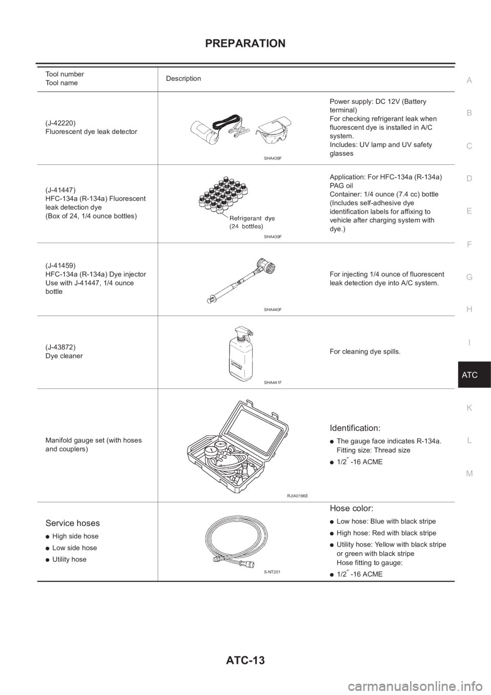
(J-42220)
Fluorescent dye leak detectorPower supply: DC 12V (Battery
terminal)
For checking refrigerant leak when
fluorescent dye is installed in A/C
system.
Includes: UV lamp and UV safety
glasses
(J-41447)
HFC-134a (R-134a) Fluorescent
leak detection dye
(Box of 24, 1/4 ounce bottles)Application: For HFC-134a (R-134a)
PAG oil
Container: 1/4 ounce (7.4 cc) bottle
(Includes self-adhesive dye
identification labels for affixing to
vehicle after charging system with
dye.)
(J-41459)
HFC-134a (R-134a) Dye injector
Use with J-41447, 1/4 ounce
bottleFor injecting 1/4 ounce of fluorescent
leak detection dye into A/C system.
(J-43872)
Dye cleanerFor cleaning dye spills.
Manifold gauge set (with hoses
and couplers)
Identification:
●The gauge face indicates R-134a.
Fitting size: Thread size
●1/2″ -16 ACME
Service hoses
●High side hose
●Low side hose
●Utility hose
Hose color:
●Low hose: Blue with black stripe
●High hose: Red with black stripe
●Utility hose: Yellow with black stripe
or green with black stripe
Hose fitting to gauge:
●1/2″ -16 ACME Tool number
Tool nameDescription
SHA438F
SHA439F
SHA440F
SHA441F
RJIA0196E
S-NT201
Page 2023 of 3189

TROUBLE DIAGNOSIS
ATC-43
C
D
E
F
G
H
I
K
L
MA
B
AT C
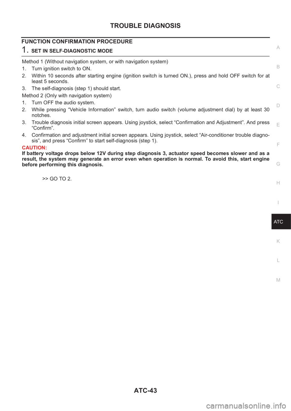
FUNCTION CONFIRMATION PROCEDURE
1.SET IN SELF-DIAGNOSTIC MODE
Method 1 (Without navigation system, or with navigation system)
1. Turn ignition switch to ON.
2. Within 10 seconds after starting engine (ignition switch is turned ON.), press and hold OFF switch for at
least 5 seconds.
3. The self-diagnosis (step 1) should start.
Method 2 (Only with navigation system)
1. Turn OFF the audio system.
2. While pressing “Vehicle Information” switch, turn audio switch (volume adjustment dial) by at least 30
notches.
3. Trouble diagnosis initial screen appears. Using joystick, select “Confirmation and Adjustment”. And press
“Confirm”.
4. Confirmation and adjustment initial screen appears. Using joystick, select “Air-conditioner trouble diagno-
sis”, and press “Confirm” to start self-diagnosis (step 1).
CAUTION:
If battery voltage drops below 12V during step diagnosis 3, actuator speed becomes slower and as a
result, the system may generate an error even when operation is normal. To avoid this, start engine
before performing this diagnosis.
>> GO TO 2.
Page 2030 of 3189
ATC-50
TROUBLE DIAGNOSIS
When battery cable is disconnected, trimmer operation is canceled. Temperature set becomes that of initial
condition, i.e. 0°C (0°F).
RJIA0778E