2003 NISSAN ALMERA N16 battery
[x] Cancel search: batteryPage 2057 of 3189
TROUBLE DIAGNOSIS
ATC-77
C
D
E
F
G
H
I
K
L
MA
B
AT C
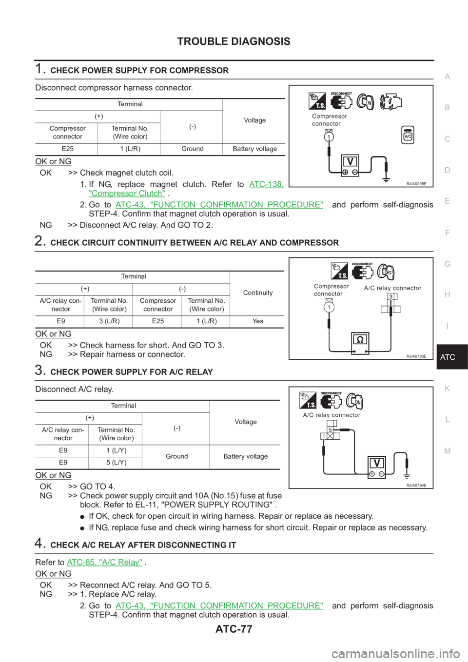
1.CHECK POWER SUPPLY FOR COMPRESSOR
Disconnect compressor harness connector.
OK or NG
OK >> Check magnet clutch coil.
1. If NG, replace magnet clutch. Refer to ATC-138,
"Compressor Clutch" .
2. Go to AT C - 4 3 , "
FUNCTION CONFIRMATION PROCEDURE" and perform self-diagnosis
STEP-4. Confirm that magnet clutch operation is usual.
NG >> Disconnect A/C relay. And GO TO 2.
2.CHECK CIRCUIT CONTINUITY BETWEEN A/C RELAY AND COMPRESSOR
OK or NG
OK >> Check harness for short. And GO TO 3.
NG >> Repair harness or connector.
3.CHECK POWER SUPPLY FOR A/C RELAY
Disconnect A/C relay.
OK or NG
OK >> GO TO 4.
NG >> Check power supply circuit and 10A (No.15) fuse at fuse
block. Refer to EL-11, "POWER SUPPLY ROUTING" .
●If OK, check for open circuit in wiring harness. Repair or replace as necessary.
●If NG, replace fuse and check wiring harness for short circuit. Repair or replace as necessary.
4.CHECK A/C RELAY AFTER DISCONNECTING IT
Refer to ATC-85, "
A/C Relay" .
OK or NG
OK >> Reconnect A/C relay. And GO TO 5.
NG >> 1. Replace A/C relay.
2. Go to AT C - 4 3 , "
FUNCTION CONFIRMATION PROCEDURE" and perform self-diagnosis
STEP-4. Confirm that magnet clutch operation is usual.
Terminal
Vo lta g e (+)
(-)
Compressor
connectorTe r m i n a l N o .
(Wire color)
E25 1 (L/R) Ground Battery voltage
RJIA0295E
Terminal
Continuity (+) (-)
A/C relay con-
nectorTerminal No.
(Wire color)Compressor
connectorTerminal No.
(Wire color)
E9 3 (L/R) E25 1 (L/R) Yes
RJIA0793E
Terminal
Vo l ta g e (+)
(-)
A/C relay con-
nectorTerminal No.
(Wire color)
E9 1 (L/Y)
Ground Battery voltage
E9 5 (L/Y)
RJIA0794E
Page 2062 of 3189
ATC-82
TROUBLE DIAGNOSIS
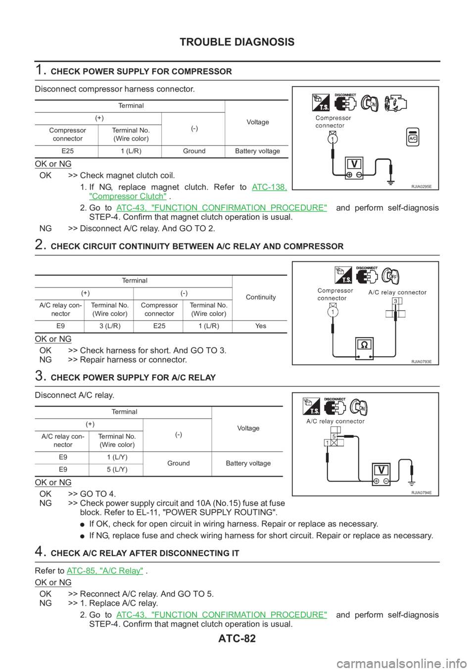
1. CHECK POWER SUPPLY FOR COMPRESSOR
Disconnect compressor harness connector.
OK or NG
OK >> Check magnet clutch coil.
1. If NG, replace magnet clutch. Refer to ATC-138,
"Compressor Clutch" .
2. Go to AT C - 4 3 , "
FUNCTION CONFIRMATION PROCEDURE" and perform self-diagnosis
STEP-4. Confirm that magnet clutch operation is usual.
NG >> Disconnect A/C relay. And GO TO 2.
2. CHECK CIRCUIT CONTINUITY BETWEEN A/C RELAY AND COMPRESSOR
OK or NG
OK >> Check harness for short. And GO TO 3.
NG >> Repair harness or connector.
3. CHECK POWER SUPPLY FOR A/C RELAY
Disconnect A/C relay.
OK or NG
OK >> GO TO 4.
NG >> Check power supply circuit and 10A (No.15) fuse at fuse
block. Refer to EL-11, "POWER SUPPLY ROUTING".
●If OK, check for open circuit in wiring harness. Repair or replace as necessary.
●If NG, replace fuse and check wiring harness for short circuit. Repair or replace as necessary.
4. CHECK A/C RELAY AFTER DISCONNECTING IT
Refer to AT C - 8 5 , "
A/C Relay" .
OK or NG
OK >> Reconnect A/C relay. And GO TO 5.
NG >> 1. Replace A/C relay.
2. Go to AT C - 4 3 , "
FUNCTION CONFIRMATION PROCEDURE" and perform self-diagnosis
STEP-4. Confirm that magnet clutch operation is usual.
Te r m i n a l
Voltag e (+)
(-)
Compressor
connectorTerminal No.
(Wire color)
E25 1 (L/R) Ground Battery voltage
RJIA0295E
Terminal
Continuity (+) (-)
A/C relay con-
nectorTerminal No.
(Wire color)Compressor
connectorTe r m i n a l N o .
(Wire color)
E9 3 (L/R) E25 1 (L/R) Yes
RJIA0793E
Te r m i n a l
Voltage (+)
(-)
A/C relay con-
nectorTerminal No.
(Wire color)
E9 1 (L/Y)
Ground Battery voltage
E9 5 (L/Y)
RJIA0794E
Page 2123 of 3189
REFRIGERANT LINES
ATC-143
C
D
E
F
G
H
I
K
L
MA
B
AT C
Dual-pressure SwitchEJS0020Q
REMOVAL AND INSTALLATION
1. Use refrigerant collecting equipment (for HFC-134a) to discharge refrigerant.
2. Remove the liquid tank.
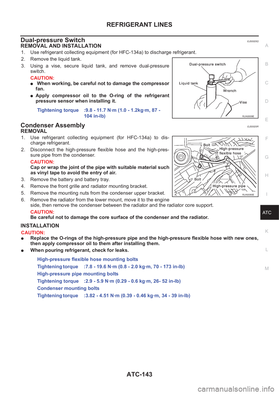
3. Using a vise, secure liquid tank, and remove dual-pressure
switch.
CAUTION:
● When working, be careful not to damage the compressor
fan.
●Apply compressor oil to the O-ring of the refrigerant
pressure sensor when installing it.
Condenser AssemblyEJS0020R
REMOVAL
1. Use refrigerant collecting equipment (for HFC-134a) to dis-
charge refrigerant.
2. Disconnect the high-pressure flexible hose and the high-pres-
sure pipe from the condenser.
CAUTION:
Cap or wrap the joint of the pipe with suitable material such
as vinyl tape to avoid the entry of air.
3. Remove the battery and battery tray.
4. Remove the front grille and radiator mounting bracket.
5. Remove the mounting nuts from the condenser upper bracket.
6. Remove the radiator from the lower mount, move it to the engine
side, then remove the condenser between the radiator and the radiator core support.
CAUTION:
Be careful not to damage the core surface of the condenser and the radiator.
INSTALLATION
CAUTION:
●Replace the O-rings of the high-pressure pipe and the high-pressure flexible hose with new ones,
then apply compressor oil to them after installing them.
●When pouring refrigerant, check for leaks.Tightening torque :9.8 - 11.7 N·m (1.0 - 1.2kg·m, 87 -
104 in-lb)
RJIA0699E
RJIA0080E
High-pressure flexible hose mounting bolts
Tightening torque :7.8 - 19.6 N·m (0.8 - 2.0 kg·m, 70 - 173 in-lb)
High-pressure pipe mounting bolts
Tightening torque :2.9 - 5.9 N·m (0.29 - 0.6 kg·m, 26- 52 in-lb)
Condenser mounting bolts
Tightening torque :3.82 - 4.51 N·m (0.39 - 0.46 kg·m, 34 - 39 in-lb)
Page 2192 of 3189
pressure such that vehicle stopping time equals 3 to 5 sec-
onds.
3. To cool the brake system, drive the vehicle at 50 km/h (31
MPH) for 1 minute without stopping.
4. Repeat steps 1 to 3, 10 times or more to complete the burnish-
ing procedure.
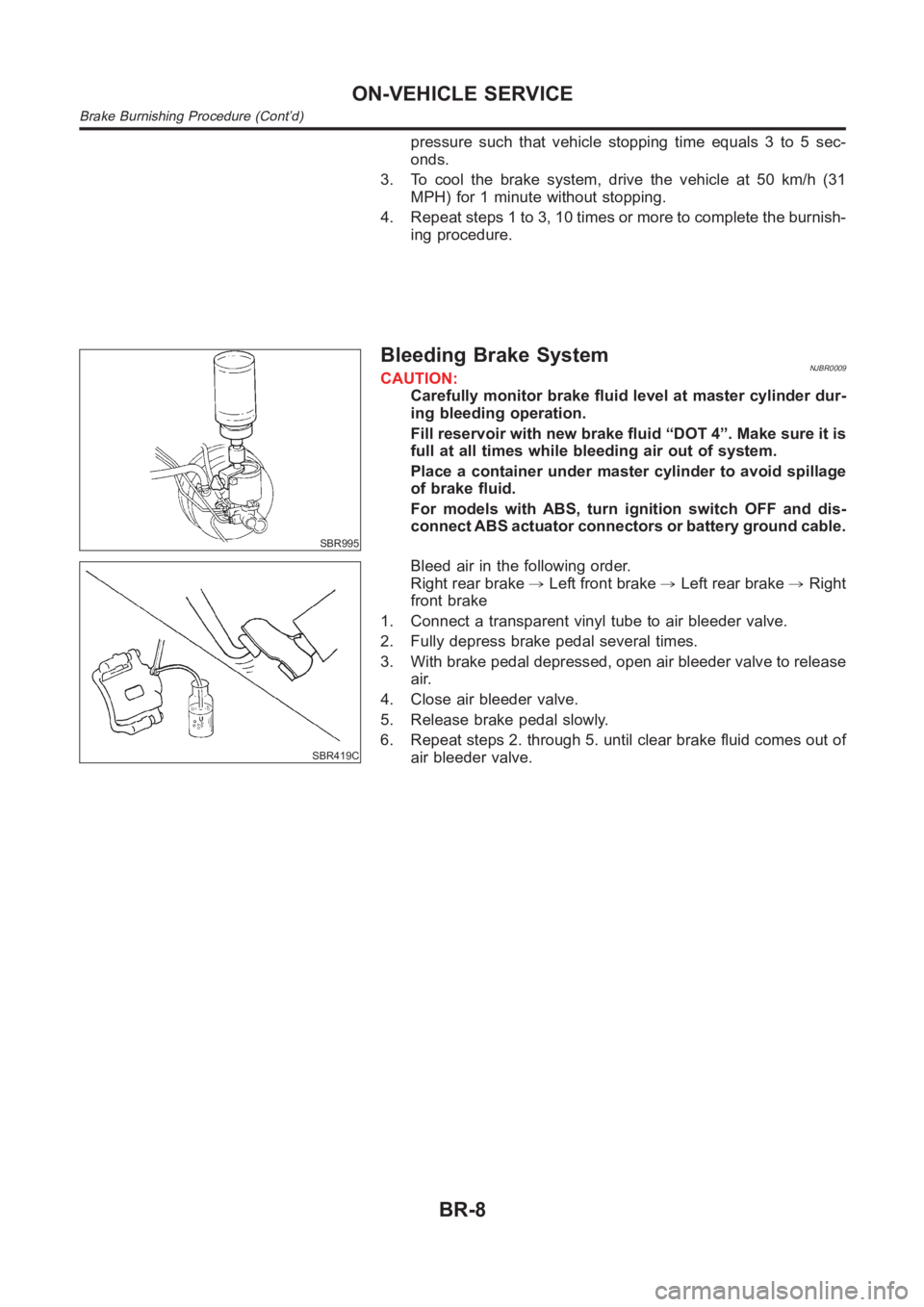
SBR995
Bleeding Brake SystemNJBR0009CAUTION:
Carefully monitor brake fluid level at master cylinder dur-
ing bleeding operation.
Fill reservoir with new brake fluid “DOT 4”. Make sure it is
full at all times while bleeding air out of system.
Place a container under master cylinder to avoid spillage
of brake fluid.
For models with ABS, turn ignition switch OFF and dis-
connect ABS actuator connectors or battery ground cable.
SBR419C
Bleed air in the following order.
Right rear brake,Left front brake,Left rear brake,Right
front brake
1. Connect a transparent vinyl tube to air bleeder valve.
2. Fully depress brake pedal several times.
3. With brake pedal depressed, open air bleeder valve to release
air.
4. Close air bleeder valve.
5. Release brake pedal slowly.
6. Repeat steps 2. through 5. until clear brake fluid comes out of
air bleeder valve.
ON-VEHICLE SERVICE
Brake Burnishing Procedure (Cont’d)
BR-8
Page 2239 of 3189
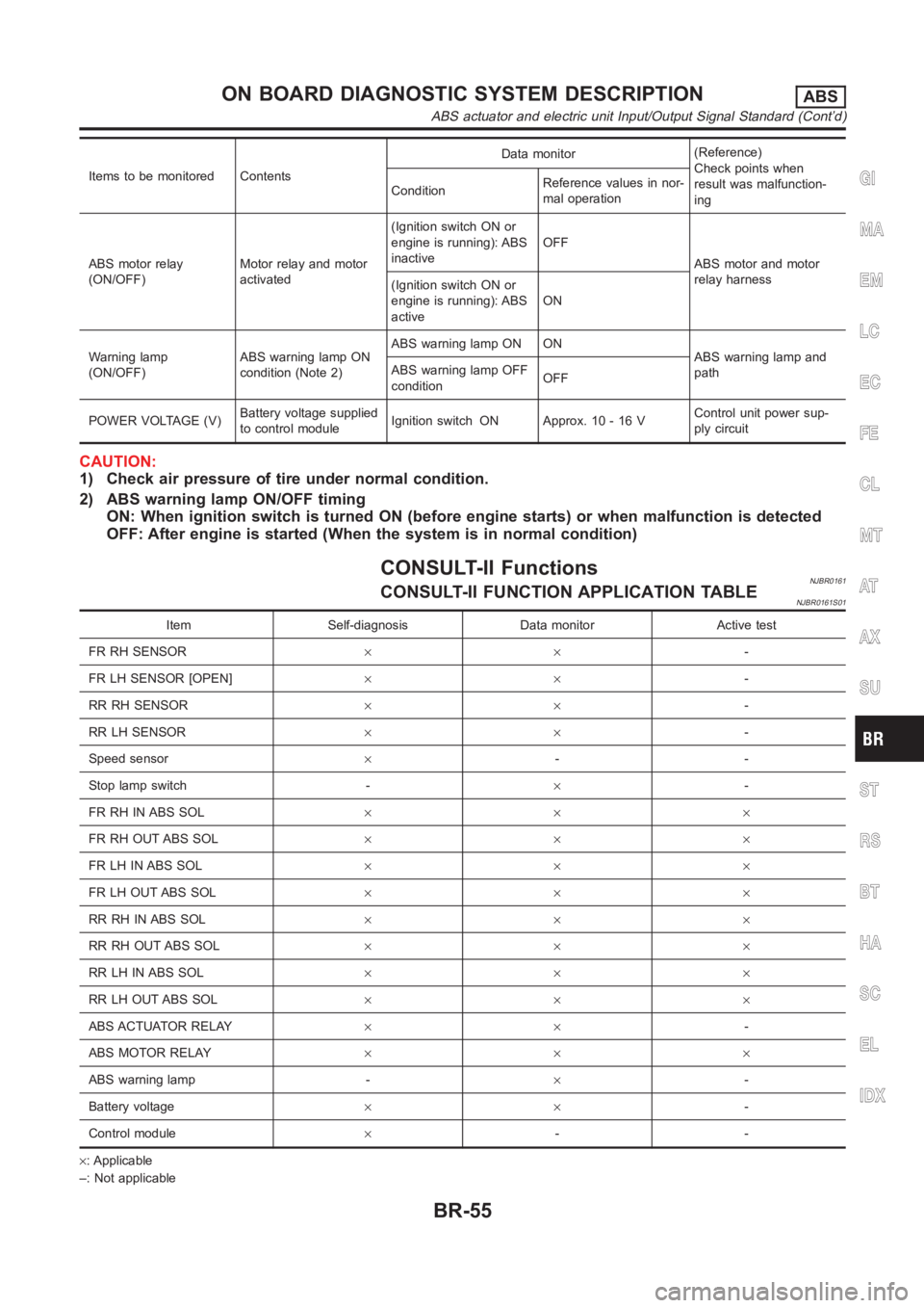
Items to be monitored ContentsData monitor(Reference)
Check points when
result was malfunction-
ing ConditionReference values in nor-
mal operation
ABS motor relay
(ON/OFF)Motor relay and motor
activated(Ignition switch ON or
engine is running): ABS
inactiveOFF
ABS motor and motor
relay harness
(Ignition switch ON or
engine is running): ABS
activeON
Warning lamp
(ON/OFF)ABS warning lamp ON
condition (Note 2)ABS warning lamp ON ON
ABS warning lamp and
path ABS warning lamp OFF
conditionOFF
POWER VOLTAGE (V)Battery voltage supplied
to control moduleIgnition switch ON Approx. 10 - 16 VControl unit power sup-
ply circuit
CAUTION:
1) Check air pressure of tire under normal condition.
2) ABS warning lamp ON/OFF timing
ON: When ignition switch is turned ON (before engine starts) or when malfunction is detected
OFF: After engine is started (When the system is in normal condition)
CONSULT-II FunctionsNJBR0161CONSULT-II FUNCTION APPLICATION TABLENJBR0161S01
Item Self-diagnosis Data monitor Active test
FR RH SENSOR××-
FR LH SENSOR [OPEN]××-
RR RH SENSOR××-
RR LH SENSOR××-
Speed sensor×--
Stop lamp switch -×-
FR RH IN ABS SOL×××
FR RH OUT ABS SOL×××
FR LH IN ABS SOL×××
FR LH OUT ABS SOL×××
RR RH IN ABS SOL×××
RR RH OUT ABS SOL×××
RR LH IN ABS SOL×××
RR LH OUT ABS SOL×××
ABS ACTUATOR RELAY××-
ABS MOTOR RELAY×××
ABS warning lamp -×-
Battery voltage××-
Control module×--
×: Applicable
–: Not applicable
GI
MA
EM
LC
EC
FE
CL
MT
AT
AX
SU
ST
RS
BT
HA
SC
EL
IDX
ON BOARD DIAGNOSTIC SYSTEM DESCRIPTIONABS
ABS actuator and electric unit Input/Output Signal Standard (Cont’d)
BR-55
Page 2242 of 3189
![NISSAN ALMERA N16 2003 Electronic Repair Manual Faulty lines Malfunction detecting condition Check harness
RR RH OUT ABS SOL
[OPEN] [SHORT]At RH rear wheel ABS outlet solenoid valve, following
conditions occur: open circuit, output voltage is abnor NISSAN ALMERA N16 2003 Electronic Repair Manual Faulty lines Malfunction detecting condition Check harness
RR RH OUT ABS SOL
[OPEN] [SHORT]At RH rear wheel ABS outlet solenoid valve, following
conditions occur: open circuit, output voltage is abnor](/manual-img/5/57350/w960_57350-2241.png)
Faulty lines Malfunction detecting condition Check harness
RR RH OUT ABS SOL
[OPEN] [SHORT]At RH rear wheel ABS outlet solenoid valve, following
conditions occur: open circuit, output voltage is abnor-
mally lower or higher than control value by short to
ground on control line.
ABS solenoid valve and actua-
tor relay harness
RR LH OUT ABS SOL
[OPEN] [SHORT]At LH rear wheel ABS outlet solenoid valve, following
conditions occur: open circuit, output voltage is abnor-
mally lower or higher than control value by short to
ground on control line.
ABS motor [ON error]ABS actuator motor turned ON when the ABS motor is
controlled OFF.
ABS motor relay and harness
ABS motor [OFF error]ABS actuator motor turned OFF when the ABS motor is
controlled ON.
ABS actuator relay [ON error] ABS actuator relay turned ON wheel it is controlled OFF.
ABS actuator relay and har-
ness ABS ACTUATOR RELAY
[OFF abnormal]ABS actuator relay turned OFF wheel it is controlled ON.
BATTERY VOLTAGE [ABNORMAL]Power source voltage supplied to ABS actuator and elec-
tric unit is abnormally low.ABS actuator and electric unit
power supply circuit
CONTROL UNITFunction of calculation in ABS actuator and electric unit
has failed.ABS actuator and electric unit,
power and ground circuits
(Note 1): When vehicle was stuck on slippery road, and spin its wheels for Approx. 10 - 80 seconds (the period depends on vehicle
speed). ABS warning lamp may come on. However, this is not abnormal.
(Note 2): Repair short circuit in sensor. ABS warning lamp will come on whenignition switch is turned ON. According to self-diagnosis
operation procedure, drive vehicle at Approx. 30 km/h (19 MPH). Then checkABS warning lamp goes out in about one minute.
DATA MONITORNJBR0161S03For details of data monitor function, refer to CONSULT-II
Instruction Manual.
Operation ProcedureNJBR0161S03011. Turn the ignition switch to OFF.
2. Connect CONSULT-II connector to data link connector on
vehicle.
3. Turn ignition switch ON.
MBIB0233E
4. Touch “START (NISSAN BASED VHCL)” on the display.
ON BOARD DIAGNOSTIC SYSTEM DESCRIPTIONABS
CONSULT-II Functions (Cont’d)
BR-58
Page 2244 of 3189
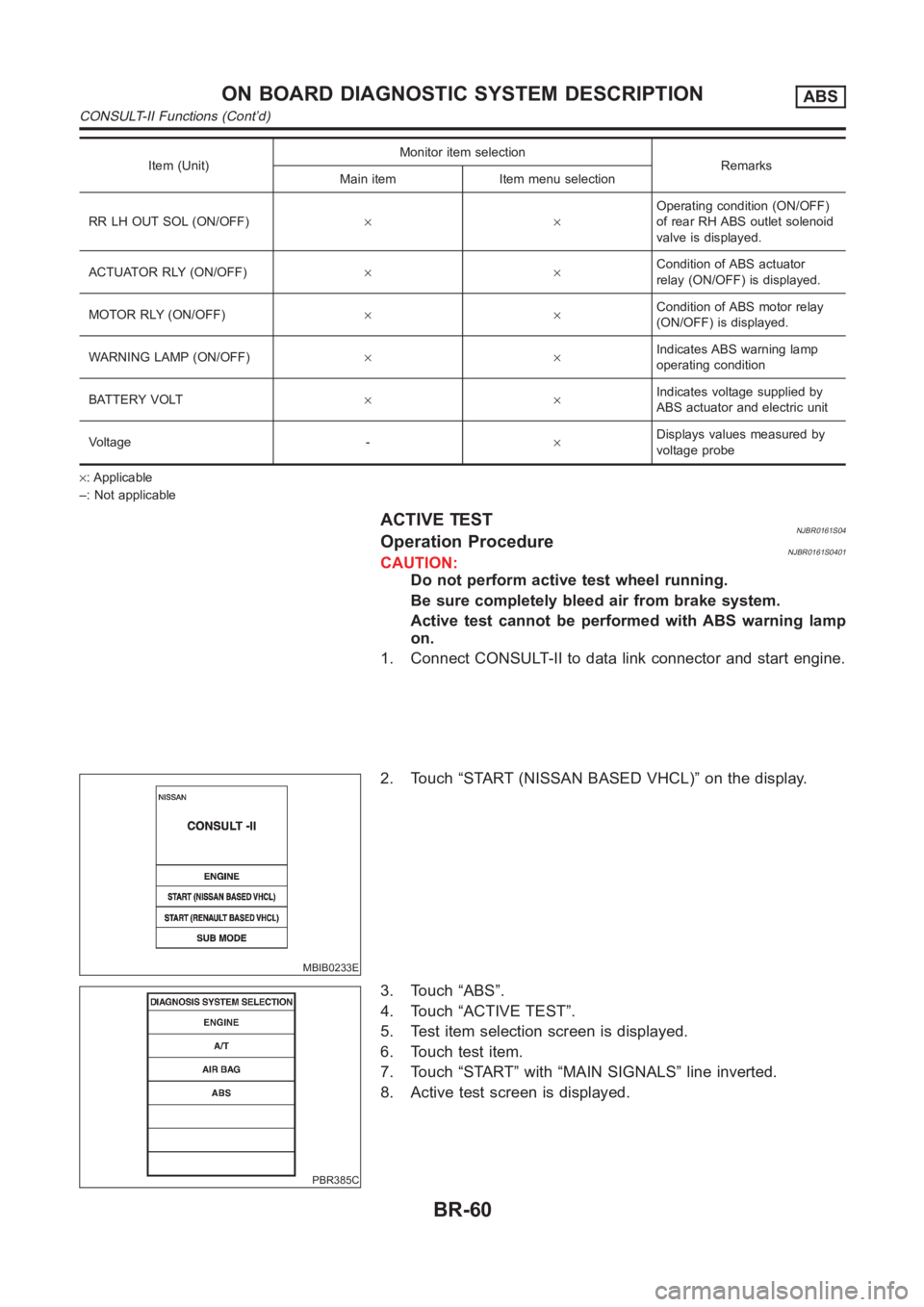
Item (Unit)Monitor item selection
Remarks
Main item Item menu selection
RR LH OUT SOL (ON/OFF)××Operating condition (ON/OFF)
of rear RH ABS outlet solenoid
valve is displayed.
ACTUATOR RLY (ON/OFF)××Condition of ABS actuator
relay (ON/OFF) is displayed.
MOTOR RLY (ON/OFF)××Condition of ABS motor relay
(ON/OFF) is displayed.
WARNING LAMP (ON/OFF)××Indicates ABS warning lamp
operating condition
BATTERY VOLT××Indicates voltage supplied by
ABS actuator and electric unit
Voltage -×Displays values measured by
voltage probe
×: Applicable
–: Not applicable
ACTIVE TESTNJBR0161S04Operation ProcedureNJBR0161S0401CAUTION:
Do not perform active test wheel running.
Be sure completely bleed air from brake system.
Active test cannot be performed with ABS warning lamp
on.
1. Connect CONSULT-II to data link connector and start engine.
MBIB0233E
2. Touch “START (NISSAN BASED VHCL)” on the display.
PBR385C
3. Touch “ABS”.
4. Touch “ACTIVE TEST”.
5. Test item selection screen is displayed.
6. Touch test item.
7. Touch “START” with “MAIN SIGNALS” line inverted.
8. Active test screen is displayed.
ON BOARD DIAGNOSTIC SYSTEM DESCRIPTIONABS
CONSULT-II Functions (Cont’d)
BR-60
Page 2246 of 3189
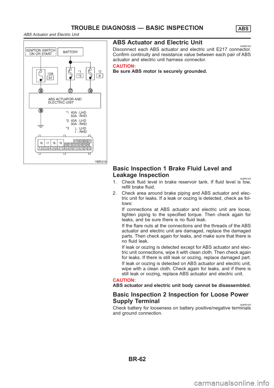
YBR319
ABS Actuator and Electric UnitNJBR0162Disconnect each ABS actuator and electric unit E217 connector.
Confirm continuity and resistance value between each pair of ABS
actuator and electric unit harness connector.
CAUTION:
Be sure ABS motor is securely grounded.
Basic Inspection 1 Brake Fluid Level and
Leakage Inspection
NJBR01631. Check fluid level in brake reservoir tank. If fluid level is low,
refill brake fluid.
2. Check area around brake piping and ABS actuator and elec-
tric unit for leaks. If a leak or oozing is detected, check as fol-
lows:
If connections at ABS actuator and electric unit are loose,
tighten piping to the specified torque. Then check again for
leaks, and be sure there is no fluid leak.
If the flare nuts at the connections and the threads of the ABS
actuator and electric unit are damaged, replace the damaged
parts. Then check again for leaks, and make sure that there is
no fluid leak.
If leak or oozing is detected except for ABS actuator and elec-
tric unit connections, wipe it with clean cloth. Then check again
for leaks. If there is still leak or oozing, replace damaged part.
If leak or oozing is detected on ABS actuator and electric unit,
wipe with a clean cloth. Check again for leaks, and if there is
still leak or oozing, replace ABS actuator and electric unit.
CAUTION:
ABS actuator and electric unit body cannot be disassembled.
Basic Inspection 2 Inspection for Loose Power
Supply Terminal
NJBR0164Check battery for looseness on battery positive/negative terminals
and ground connection.
TROUBLE DIAGNOSIS — BASIC INSPECTIONABS
ABS Actuator and Electric Unit
BR-62