Page 2549 of 3189

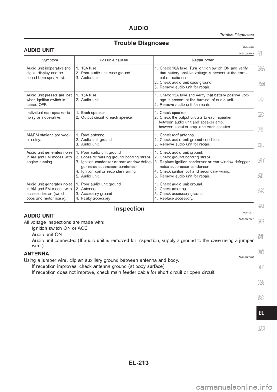
Trouble DiagnosesNJEL0385AUDIO UNITNJEL0385S05
Symptom Possible causes Repair order
Audio unit inoperative (no
digital display and no
sound from speakers).1. 10A fuse
2. Poor audio unit case ground
3. Audio unit1. Check 10A fuse. Turn ignition switch ON and verify
that battery positive voltage is present at the termi-
nal of audio unit.
2. Check audio unit case ground.
3. Remove audio unit for repair.
Audio unit presets are lost
when ignition switch is
turned OFF.1. 15A fuse
2. Audio unit1. Check 15A fuse and verify that battery positive volt-
age is present at the terminal of audio unit.
2. Remove audio unit for repair.
Individual rear speaker is
noisy or inoperative.1. Each speaker
2. Output circuit to each speaker1. Check speaker.
2. Check the output circuits to each speaker
between audio unit and speaker amp.
between speaker amp. and each speaker.
AM/FM stations are weak
or noisy.1. Roof antenna
2. Audio unit ground
3. Audio unit1. Check roof antenna.
2. Check audio unit ground condition.
3. Remove audio unit for repair.
Audio unit generates noise
in AM and FM modes with
engine running.1. Poor audio unit ground
2. Loose or missing ground bonding straps
3. Ignition condenser or rear window defog-
ger noise suppressor condenser
4. Ignition coil or secondary wiring
5. Audio unit1. Check audio unit ground.
2. Check ground bonding straps.
3. Replace ignition condenser or rear window defogger
noise suppressor condenser.
4. Check ignition coil and secondary wiring.
5. Remove audio unit for repair.
Audio unit generates noise
in AM and FM modes with
accessories on (switch
pops and motor noise).1. Poor audio unit ground
2. Antenna
3. Accessory ground
4. Faulty accessory1. Check audio unit ground.
2. Check antenna.
3. Check accessory ground.
4. Replace accessory.
InspectionNJEL0221AUDIO UNITNJEL0221S01All voltage inspections are made with:
Ignition switch ON or ACC
Audio unit ON
Audio unit connected (If audio unit is removed for inspection, supply a ground to the case using a jumper
wire.)
ANTENNANJEL0221S02Using a jumper wire, clip an auxiliary ground between antenna and body.
If reception improves, check antenna ground (at body surface).
If reception does not improve, check main feeder cable for short circuit oropen circuit.
GI
MA
EM
LC
EC
FE
CL
MT
AT
AX
SU
BR
ST
RS
BT
HA
SC
IDX
AUDIO
Trouble Diagnoses
EL-213
Page 2557 of 3189
TERMINALS
SIGNALCONDITION
VOLTAGE (+)
(–)
TERMI-
NALWIRE
COLORIGNITION
SWITCHOPERATION
15 — —Shield
ground—— —
16 L GroundA/C clock
signalON —
SKIA0174E
19 L/B GroundVehicle
speed signal
(2-pulse)ONWhen vehicle speed is approx. 20
km/h (12 MPH)
ELF1080D
21 B Ground — — — —
22 Y/G GroundIgnition sig-
nalON — —
23 Y GroundBattery
powerOFF — Battery voltage
24 P Ground ACC signal ACC — —
Terminals and Reference Value for
Multifunction Switch
NJEL0559
TERMINALS
SIGNALCONDITION
DATA (+)
(–)
TERMINALWIRE
COLORIGNITION
SWITCHOPERATION
1 B Ground Ground ON — Apporox. 0V
6 P Ground ACC ACC — Battery voltage
11 L GroundCommunication
signal (+)ON —
SKIA0175E
GI
MA
EM
LC
EC
FE
CL
MT
AT
AX
SU
BR
ST
RS
BT
HA
SC
IDX
VFD DISPLAY
Terminals and Reference Value for Display Unit (Cont’d)
EL-221
Page 2578 of 3189
![NISSAN ALMERA N16 2003 Electronic Repair Manual Warning indicatorsWarning lamps in
instrument panelWarning detection and cancel conditions Cases of malfunction
DOOR OPEN DoorDetection conditionVehicle is running [approx. 5
km/h (3 MPH) or faster] a NISSAN ALMERA N16 2003 Electronic Repair Manual Warning indicatorsWarning lamps in
instrument panelWarning detection and cancel conditions Cases of malfunction
DOOR OPEN DoorDetection conditionVehicle is running [approx. 5
km/h (3 MPH) or faster] a](/manual-img/5/57350/w960_57350-2577.png)
Warning indicatorsWarning lamps in
instrument panelWarning detection and cancel conditions Cases of malfunction
DOOR OPEN DoorDetection conditionVehicle is running [approx. 5
km/h (3 MPH) or faster] and door
ajar of any of the doors is
detected.Doorisopen
Cancel conditionVehicle is stopped and all the
doors lock.
ABS ABSDetection conditionWarning lamp ON signal is
detected when engine is running.
ABS control system mal-
function
Cancel conditionWarning lamp OFF signal is
detected.
ESP ELECTRONIC
CONTROL SYSTEMESPDetection conditionWarning lamp ON signal is
detected when engine is running.
ESP system malfunction
Cancel conditionWarning lamp OFF signal is
detected.
CVT ELECTRONIC
CONTROL SYSTEMCVTDetection conditionWarning lamp ON signal is
detected after ignition switch is
turned ON.
TCM system malfunction
Cancel conditionWarning lamp OFF signal is
detected.
CRUISE CONTROL
SYSTEMCRUISEDetection conditionWarning lamp ON signal is
detected after ignition switch is
turned ON.
ICC system malfunction
Cancel conditionWarning lamp OFF signal is
detected.
Precautions for Display Unit ReplacementNJEL0572Record the following memorized contents before replacing the control unit.
Preset frequency
Area for indicating station, selection of overlapped stations
Program status
Volume balance memory set values
Equalizer memory set values
Brightness of light when ON/OFF
Dimming switching
Display color switching
Replace the display unit after disconnecting both battery cables.
Component Parts and Harness Connector and
Harness Connector Location
NJEL0573For details, refer to “ELECTRICAL UNIT LOCATION” (EL-543) and “HARNESS LAYOUT” (EL-550).
LCD DISPLAY
System Description (Cont’d)
EL-242
Page 2586 of 3189
Trouble DiagnosesNJEL0225
Symptom Possible cause Repair order
Power sunroof cannot be operated
using any switch.1. 10A fuse, 30A fusible link and
M4 circuit breaker
2. Sunroof motor ground circuit
3. Sunroof switch
4. Sunroof switch circuit
5. Sunroof motor1. Check 10A fuse [No. 10, located in fuse block
(J/B)], 30A fusible link (letterB, located in fuse and
fusible link box) and M4 circuit breaker. Verify bat-
tery positive voltage is present at terminal 5 of sun-
roof motor. And then turn ignition switch “ON” and
verify battery positive voltage is present at terminal
2 of sunroof switch.
2. Check sunroof motor ground circuit.
3. Check sunroof switch.
4. Check harness between sunroof switch and sunroof
motor.
5. Check sunroof motor.
Power sunroof cannot be operated
using one of the sunroof switches.1. Sunroof switch
2. Sunroof switch circuit1. Check sunroof switch.
2. Check the harness between sunroof motor and sun-
roof switch.
POWER SUNROOF
Trouble Diagnoses
EL-250
Page 2596 of 3189

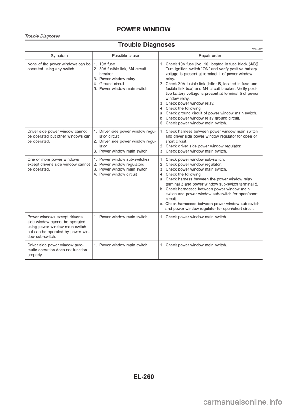
Trouble DiagnosesNJEL0501
Symptom Possible cause Repair order
None of the power windows can be
operated using any switch.1. 10A fuse
2. 30A fusible link, M4 circuit
breaker
3. Power window relay
4. Ground circuit
5. Power window main switch1. Check 10A fuse [No. 10, located in fuse block (J/B)]
Turn ignition switch “ON” and verify positive battery
voltage is present at terminal 1 of power window
relay.
2. Check 30A fusible link (letterB, located in fuse and
fusible link box) and M4 circuit breaker. Verify posi-
tive battery voltage is present at terminal 5 of power
window relay.
3. Check power window relay.
4. Check the following:
a. Check ground circuit of power window main switch.
b. Check power window relay ground circuit.
5. Check power window main switch.
Driver side power window cannot
be operated but other windows can
be operated.1. Driver side power window regu-
lator circuit
2. Driver side power window regu-
lator
3. Power window main switch1. Check harness between power window main switch
and driver side power window regulator for open or
short circuit.
2. Check driver side power window regulator.
3. Check power window main switch.
One or more power windows
except driver’s side window cannot
be operated.1. Power window sub-switches
2. Power window regulators
3. Power window main switch
4. Power window circuit1. Check power window sub-switch.
2. Check power window regulator.
3. Check power window main switch.
4. Check the following.
a. Check harness between the power window relay
terminal 3 and power window sub-switch terminal 5.
b. Check harnesses between power window main
switch and power window sub-switch for open/short
circuit.
c. Check harnesses between power window sub-switch
and power window regulator for open/short circuit.
Power windows except driver’s
side window cannot be operated
using power window main switch
but can be operated by power win-
dow sub-switch.1. Power window main switch 1. Check power window main switch.
Driver side power window auto-
matic operation does not function
properly.1. Power window main switch 1. Check power window main switch.
POWER WINDOW
Trouble Diagnoses
EL-260
Page 2638 of 3189
knob, key or multi-remote controller to “LOCK” locks the door once but thenimmediately unlocks all doors.
(signal from door unlock sensor driver side)
System initialization
System initialization is required when battery cables are reconnected. Conduct the following to release
super lock once;
— insert the key into the ignition key cylinder and turn it to ON.
— LOCK/UNLOCK operation using door key cylinder or multi-remote controller.
POWER DOOR LOCK — SUPER LOCK —
System Description (Cont’d)
EL-302
Page 2685 of 3189
NATS RELEASE SIGNAL CHECK=NJEL0477S09
1 CHECK NATS SIGNAL CIRCUIT
1. Disconnect battery cable (−) terminal.
2. Disconnect time control unit connector and NATS IMMU connector.
SEL478X
OK or NG
OK GO TO 2.
NG Repair harness.
2 CHECK NATS RELEASE SIGNAL
1. Connect time control unit connector and NATS IMMU connector.
2. Connect battery cable (−) terminal.
3. Check voltage between time control unit terminal 26 and ground.
SEL479X
OK or NG
OK Replace super lock control unit.
NG Check NATS system.
GI
MA
EM
LC
EC
FE
CL
MT
AT
AX
SU
BR
ST
RS
BT
HA
SC
IDX
POWER DOOR LOCK — SUPER LOCK —
Trouble Diagnoses/YD Engine Models without Common Rail and K9K Engine Models (Cont’d)
EL-349
Page 2687 of 3189
IGNITION SWITCH “ON” CIRCUIT CHECK=NJEL0477S11
1 CHECK IGNITION ON SIGNAL
Check voltage between time control unit terminal 1 and ground.
SEL429X
OK or NG
OK Ignition switch “ON” circuit is OK.
NGCheck the following.
10A fuse [No. 10, located in fuse block (J/B)]
Harness for open or short between time control unit and fuse
REMOTE CONTROLLER SIGNAL CHECKNJEL0477S12
1 CHECK OUTPUT SIGNAL FOR SUPER LOCK ACTUATOR BY MULTI-REMOTE CONTROLLER
1. Withdraw key from ignition key cylinder.
2. Check voltage between time control unit terminal 40 or 44 and ground.
YEL807C
OK or NG
OK System is OK.
NG Replace time control unit. (Before replacing the unit, make sure the remote controller ID
registration for time control unit and the remote controller battery onceagain.)
GI
MA
EM
LC
EC
FE
CL
MT
AT
AX
SU
BR
ST
RS
BT
HA
SC
IDX
POWER DOOR LOCK — SUPER LOCK —
Trouble Diagnoses/YD Engine Models without Common Rail and K9K Engine Models (Cont’d)
EL-351