Page 2792 of 3189

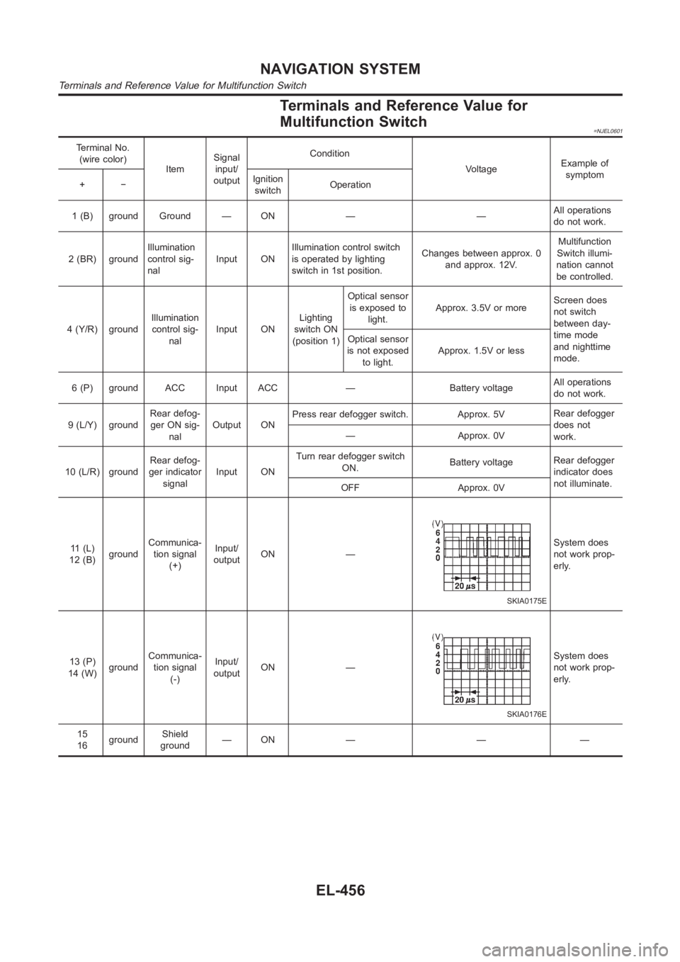
Terminals and Reference Value for
Multifunction Switch
=NJEL0601
Terminal No.
(wire color)
ItemSignal
input/
outputCondition
VoltageExample of
symptom
+−Ignition
switchOperation
1 (B) ground Ground — ON — —All operations
do not work.
2 (BR) groundIllumination
control sig-
nalInput ONIllumination control switch
is operated by lighting
switch in 1st position.Changes between approx. 0
and approx. 12V.Multifunction
Switch illumi-
nation cannot
be controlled.
4 (Y/R) groundIllumination
control sig-
nalInput ONLighting
switch ON
(position 1)Optical sensor
is exposed to
light.Approx. 3.5V or moreScreen does
not switch
between day-
time mode
and nighttime
mode. Optical sensor
is not exposed
to light.Approx. 1.5V or less
6 (P) ground ACC Input ACC — Battery voltageAll operations
do not work.
9 (L/Y) groundRear defog-
ger ON sig-
nalOutput ONPress rear defogger switch. Approx. 5VRear defogger
does not
work. — Approx. 0V
10 (L/R) groundRear defog-
ger indicator
signalInput ONTurn rear defogger switch
ON.Battery voltageRear defogger
indicator does
not illuminate.
OFF Approx. 0V
11 (L)
12 (B)groundCommunica-
tion signal
(+)Input/
outputON —
SKIA0175E
System does
not work prop-
erly.
13 (P)
14 (W)groundCommunica-
tion signal
(-)Input/
outputON —
SKIA0176E
System does
not work prop-
erly.
15
16groundShield
ground—ON — — —
NAVIGATION SYSTEM
Terminals and Reference Value for Multifunction Switch
EL-456
Page 2828 of 3189
Rear Defogger Indicator Lamp Does Not
Illuminate
NJEL0619
1 CHECK POSITION OF IGNITION SWITCH
Is ignition switch ON?
YesorNo
Ye s G O T O 2 .
No Rear defogger does not operate if ignition switch is not ON.
2 CHECK OPERATION OF REAR DEFOGGER
Does rear defogger operate when rear defogger switch is turned ON? (Does fogging disappear?)
YesorNo
Ye s G O T O 3 .
No Check rear defogger system. Refer to EL-183, “Rear Defogger Does Not Operate”.
3 CHECK REAR DEFOGGER INDICATOR LAMP SIGNALS
1. Disconnect multifunction switch connector.
2. Check voltage between multifunction switch terminal 10 (L/R) and ground.
SKIA1433E
Battery voltage should exist.
OK or NG
OK Replace multifunction switch.
NG Check harness for open or short between multifunction switch and rear defogger relay.
NAVIGATION SYSTEM
Rear Defogger Indicator Lamp Does Not Illuminate
EL-492
Page 2831 of 3189

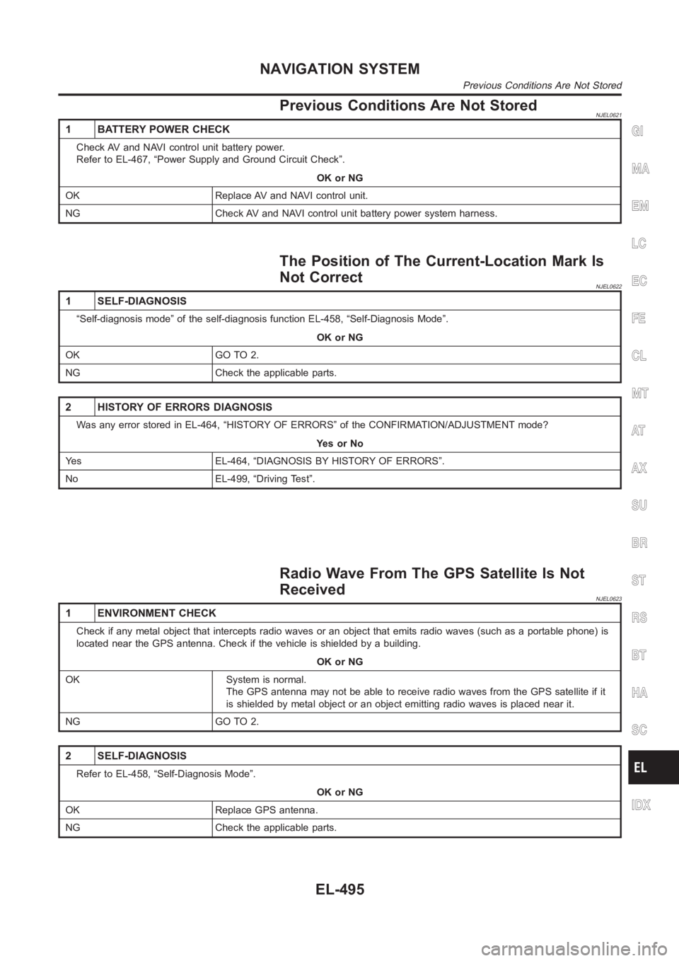
Previous Conditions Are Not StoredNJEL0621
1 BATTERY POWER CHECK
Check AV and NAVI control unit battery power.
Refer to EL-467, “Power Supply and Ground Circuit Check”.
OK or NG
OK Replace AV and NAVI control unit.
NG Check AV and NAVI control unit battery power system harness.
The Position of The Current-Location Mark Is
Not Correct
NJEL0622
1 SELF-DIAGNOSIS
“Self-diagnosis mode” of the self-diagnosis function EL-458, “Self-Diagnosis Mode”.
OK or NG
OK GO TO 2.
NG Check the applicable parts.
2 HISTORY OF ERRORS DIAGNOSIS
Was any error stored in EL-464, “HISTORY OF ERRORS” of the CONFIRMATION/ADJUSTMENT mode?
YesorNo
Yes EL-464, “DIAGNOSIS BY HISTORY OF ERRORS”.
No EL-499, “Driving Test”.
Radio Wave From The GPS Satellite Is Not
Received
NJEL0623
1 ENVIRONMENT CHECK
Check if any metal object that intercepts radio waves or an object that emits radio waves (such as a portable phone) is
located near the GPS antenna. Check if the vehicle is shielded by a building.
OK or NG
OK System is normal.
The GPS antenna may not be able to receive radio waves from the GPS satelliteif it
is shielded by metal object or an object emitting radio waves is placed nearit.
NG GO TO 2.
2 SELF-DIAGNOSIS
Refer to EL-458, “Self-Diagnosis Mode”.
OK or NG
OK Replace GPS antenna.
NG Check the applicable parts.
GI
MA
EM
LC
EC
FE
CL
MT
AT
AX
SU
BR
ST
RS
BT
HA
SC
IDX
NAVIGATION SYSTEM
Previous Conditions Are Not Stored
EL-495
Page 2855 of 3189

CIRCUIT CHECK BETWEEN TCM AND SMART ENTRANCE CONTROL UNITNJEL0540S05
1 CHECK CONNECTOR
1. Turn ignition switch OFF.
2. Disconnect the negative battery cable.
3. Check following terminals and connector for damage, bend and loose connection (connector-side and harness-side).
LHD models
Harness connector F115
Harness connector M202
RHD models
Harness connector F43
Harness connector E225
Harness connector E174
Harness connector M159
OK or NG
OK GO TO 2.
NG Repair terminal or connector.
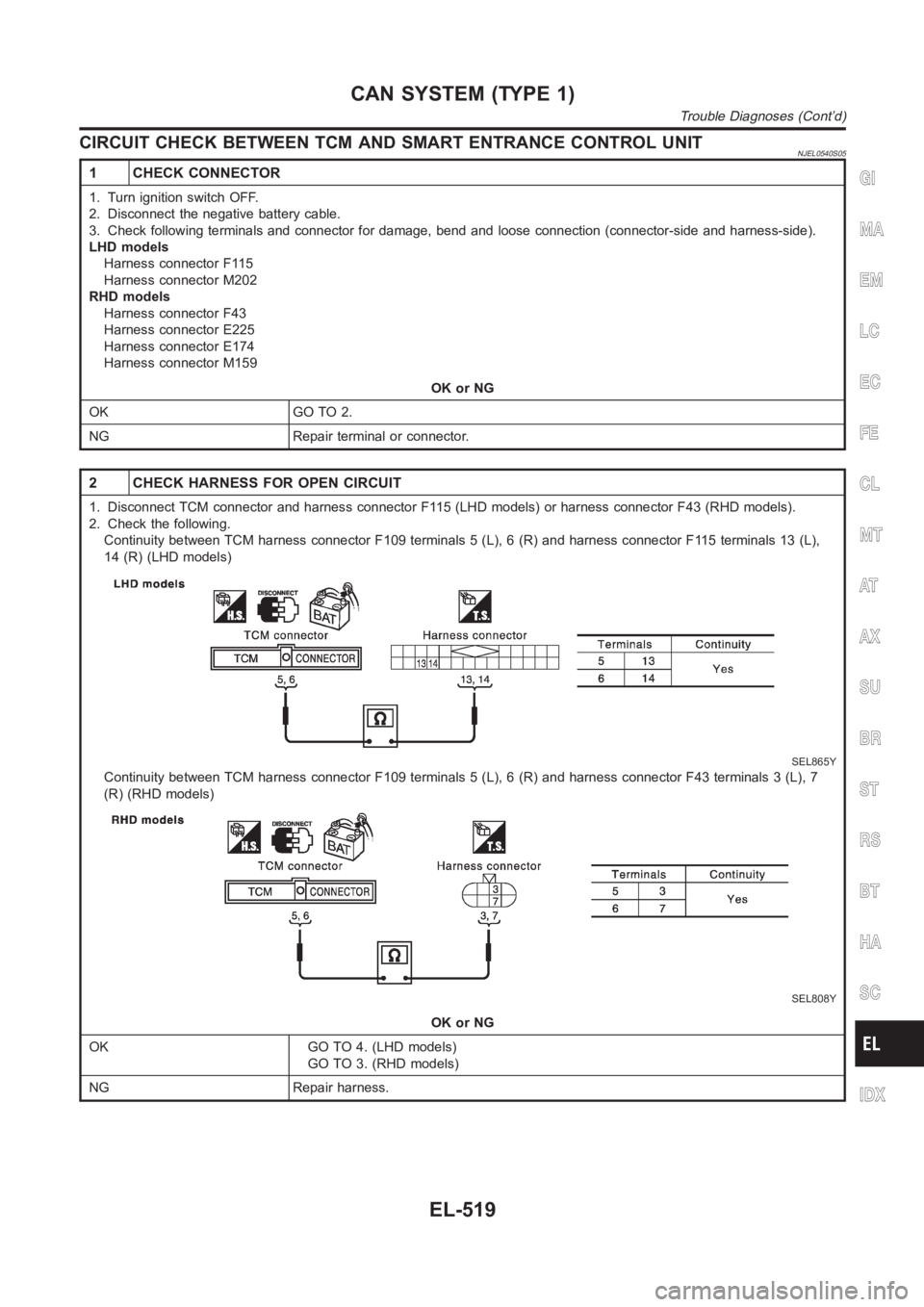
2 CHECK HARNESS FOR OPEN CIRCUIT
1. Disconnect TCM connector and harness connector F115 (LHD models) or harness connector F43 (RHD models).
2. Check the following.
Continuity between TCM harness connector F109 terminals 5 (L), 6 (R) and harness connector F115 terminals 13 (L),
14 (R) (LHD models)
SEL865Y
Continuity between TCM harness connector F109 terminals 5 (L), 6 (R) and harness connector F43 terminals 3 (L), 7
(R) (RHD models)
SEL808Y
OK or NG
OK GO TO 4. (LHD models)
GO TO 3. (RHD models)
NG Repair harness.
GI
MA
EM
LC
EC
FE
CL
MT
AT
AX
SU
BR
ST
RS
BT
HA
SC
IDX
CAN SYSTEM (TYPE 1)
Trouble Diagnoses (Cont’d)
EL-519
Page 2858 of 3189
ECM CIRCUIT CHECK=NJEL0540S06
1 CHECK CONNECTOR
1. Turn ignition switch OFF.
2. Disconnect the negative battery cable.
3. Check the terminals and connector of ECM for damage, bend and loose connection (control module-side and harness-
side).
OK or NG
OK GO TO 2.
NG Repair terminal or connector.
2 CHECK HARNESS FOR OPEN CIRCUIT
1. Disconnect ECM connector.
2. Check resistance between ECM harness connector F114 terminals 94 (L) and86(R).
SEL812Y
OK or NG
OK Replace ECM.
NG Repair harness between ECM and TCM.
CAN SYSTEM (TYPE 1)
Trouble Diagnoses (Cont’d)
EL-522
Page 2859 of 3189
TCM CIRCUIT CHECK=NJEL0540S07
1 CHECK CONNECTOR
1. Turn ignition switch OFF.
2. Disconnect the negative battery cable.
3. Check the terminals and connector of TCM for damage, bend and loose connection (control module-side and harness-
side).
OK or NG
OK GO TO 2.
NG Repair terminal or connector.
2 CHECK HARNESS FOR OPEN CIRCUIT
1. Disconnect TCM connector.
2. Check resistance between TCM harness connector F109 terminals 5 (L) and6(R).
SEL813Y
OK or NG
OK Replace TCM.
NG Repair harness between TCM and harness connector F115 (LHD models).
Repair harness between TCM and harness connector F43 (RHD models).
GI
MA
EM
LC
EC
FE
CL
MT
AT
AX
SU
BR
ST
RS
BT
HA
SC
IDX
CAN SYSTEM (TYPE 1)
Trouble Diagnoses (Cont’d)
EL-523
Page 2860 of 3189
SMART ENTRANCE CONTROL UNIT CIRCUIT CHECK=NJEL0540S08
1 CHECK CONNECTOR
1. Turn ignition switch OFF.
2. Disconnect the negative battery cable.
3. Check the terminals and connector of smart entrance control unit for damage, bend and loose connection (control unit-
side and harness-side).
OK or NG
OK GO TO 2.
NG Repair terminal or connector.
2 CHECK HARNESS FOR OPEN CIRCUIT
1. Disconnect smart entrance control unit connector.
2. Check resistance between smart entrance control unit harness connector M193 terminals 8 (L) and 11 (R).
SEL814Y
OK or NG
OK Replace smart entrance control unit.
NG Repair harness between smart entrance control unit and data link connector.
CAN SYSTEM (TYPE 1)
Trouble Diagnoses (Cont’d)
EL-524
Page 2861 of 3189

COMBINATION METER CIRCUIT CHECK=NJEL0540S09
1 CHECK CONNECTOR
1. Turn ignition switch OFF.
2. Disconnect the negative battery cable.
3. Check following terminals and connector of combination meter for damage, bend and loose connection (meter-side and
harness-side).
OK or NG
OK GO TO 2.
NG Repair terminal or connector.
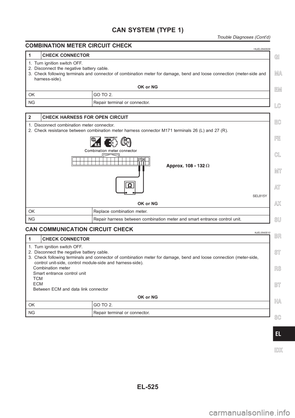
2 CHECK HARNESS FOR OPEN CIRCUIT
1. Disconnect combination meter connector.
2. Check resistance between combination meter harness connector M171 terminals 26 (L) and 27 (R).
SEL815Y
OK or NG
OK Replace combination meter.
NG Repair harness between combination meter and smart entrance control unit.
CAN COMMUNICATION CIRCUIT CHECKNJEL0540S10
1 CHECK CONNECTOR
1. Turn ignition switch OFF.
2. Disconnect the negative battery cable.
3. Check following terminals and connector of combination meter for damage, bend and loose connection (meter-side,
control unit-side, control module-side and harness-side).
Combination meter
Smart entrance control unit
TCM
ECM
Between ECM and data link connector
OK or NG
OK GO TO 2.
NG Repair terminal or connector.
GI
MA
EM
LC
EC
FE
CL
MT
AT
AX
SU
BR
ST
RS
BT
HA
SC
IDX
CAN SYSTEM (TYPE 1)
Trouble Diagnoses (Cont’d)
EL-525