2003 NISSAN ALMERA N16 battery
[x] Cancel search: batteryPage 2872 of 3189
ECM CIRCUIT CHECKNJEL0545S05
1 CHECK CONNECTOR
1. Turn ignition switch OFF.
2. Disconnect the negative battery cable.
3. Check following terminals and connector for damage, bend and loose connection (control module-side and harness-
side).
LHD models
ECM
Harness connector F115
Harness connector M202
RHD models
ECM
Harness connector F43
Harness connector E225
Harness connector E174
Harness connector M159
OK or NG
OK GO TO 2.
NG Repair terminal or connector.
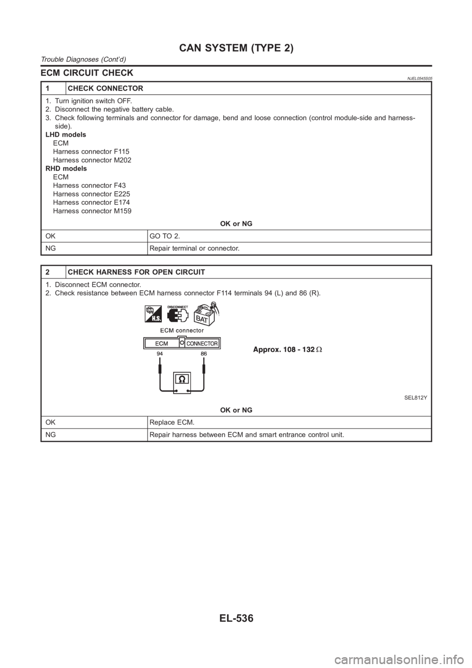
2 CHECK HARNESS FOR OPEN CIRCUIT
1. Disconnect ECM connector.
2. Check resistance between ECM harness connector F114 terminals 94 (L) and86(R).
SEL812Y
OK or NG
OK Replace ECM.
NG Repair harness between ECM and smart entrance control unit.
CAN SYSTEM (TYPE 2)
Trouble Diagnoses (Cont’d)
EL-536
Page 2873 of 3189
SMART ENTRANCE CONTROL UNIT CIRCUIT CHECK=NJEL0545S06
1 CHECK CONNECTOR
1. Turn ignition switch OFF.
2. Disconnect the negative battery cable.
3. Check terminals and connector of smart entrance control unit for damage, bend and loose connection (control unit-side
and harness-side).
OK or NG
OK GO TO 2.
NG Repair terminal or connector.
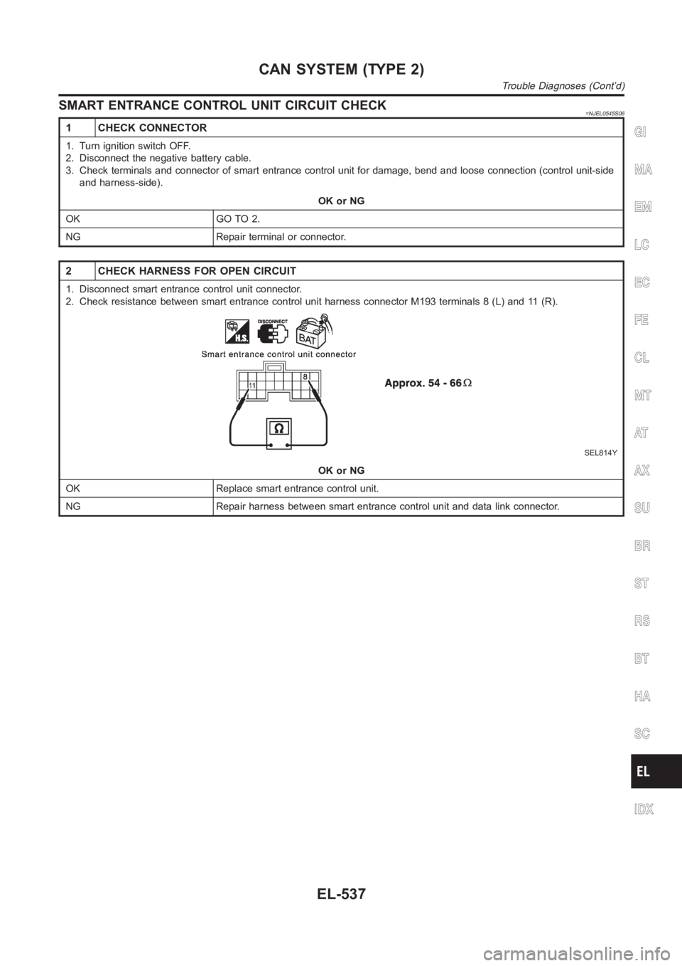
2 CHECK HARNESS FOR OPEN CIRCUIT
1. Disconnect smart entrance control unit connector.
2. Check resistance between smart entrance control unit harness connector M193 terminals 8 (L) and 11 (R).
SEL814Y
OK or NG
OK Replace smart entrance control unit.
NG Repair harness between smart entrance control unit and data link connector.
GI
MA
EM
LC
EC
FE
CL
MT
AT
AX
SU
BR
ST
RS
BT
HA
SC
IDX
CAN SYSTEM (TYPE 2)
Trouble Diagnoses (Cont’d)
EL-537
Page 2874 of 3189
COMBINATION METER CIRCUIT CHECK=NJEL0545S07
1 CHECK CONNECTOR
1. Turn ignition switch OFF.
2. Disconnect the negative battery cable.
3. Check terminals and connector of combination meter for damage, bend andloose connection (meter-side and harness-
side).
OK or NG
OK GO TO 2.
NG Repair terminal or connector.
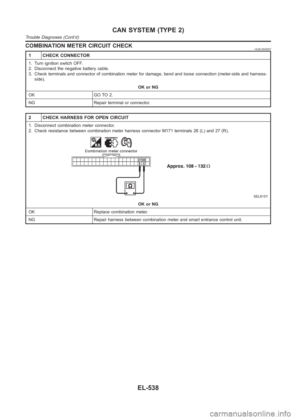
2 CHECK HARNESS FOR OPEN CIRCUIT
1. Disconnect combination meter connector.
2. Check resistance between combination meter harness connector M171 terminals 26 (L) and 27 (R).
SEL815Y
OK or NG
OK Replace combination meter.
NG Repair harness between combination meter and smart entrance control unit.
CAN SYSTEM (TYPE 2)
Trouble Diagnoses (Cont’d)
EL-538
Page 2875 of 3189
CAN COMMUNICATION CIRCUIT CHECK=NJEL0545S08
1 CHECK CONNECTOR
1. Turn ignition switch OFF.
2. Disconnect the negative battery cable.
3. Check following terminals and connector for damage, bend and loose connection (meter-side, control unit-side, control
module-side and harness-side).
Combination meter
Smart entrance control unit
ECM
Between ECM and smart entrance control unit
OK or NG
OK GO TO 2.
NG Repair terminal or connector.
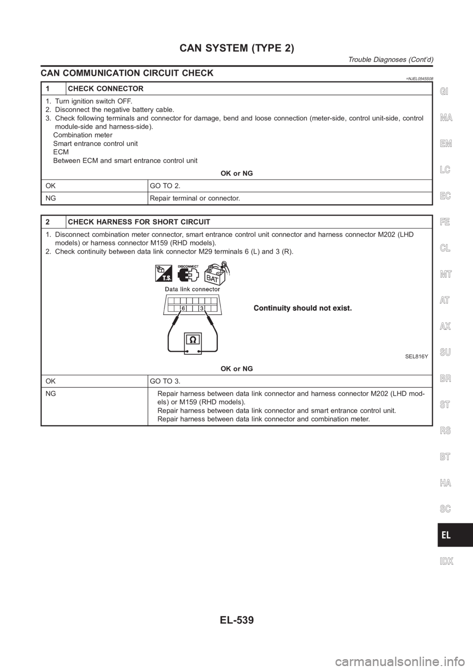
2 CHECK HARNESS FOR SHORT CIRCUIT
1. Disconnect combination meter connector, smart entrance control unit connector and harness connector M202 (LHD
models) or harness connector M159 (RHD models).
2. Check continuity between data link connector M29 terminals 6 (L) and 3 (R).
SEL816Y
OK or NG
OK GO TO 3.
NG Repair harness between data link connector and harness connector M202 (LHD mod-
els) or M159 (RHD models).
Repair harness between data link connector and smart entrance control unit.
Repair harness between data link connector and combination meter.
GI
MA
EM
LC
EC
FE
CL
MT
AT
AX
SU
BR
ST
RS
BT
HA
SC
IDX
CAN SYSTEM (TYPE 2)
Trouble Diagnoses (Cont’d)
EL-539
Page 2989 of 3189
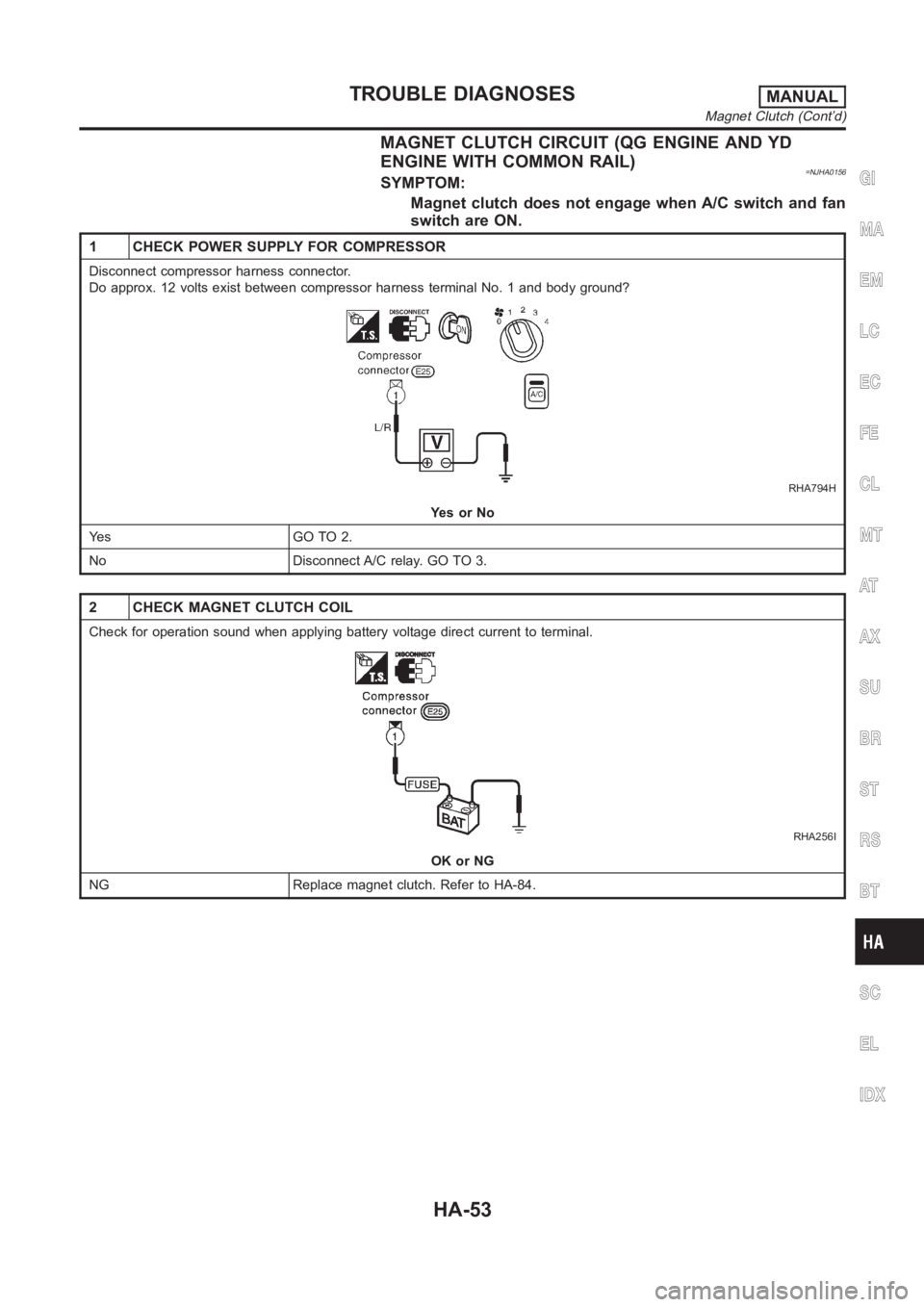
MAGNET CLUTCH CIRCUIT (QG ENGINE AND YD
ENGINE WITH COMMON RAIL)
=NJHA0156SYMPTOM:
Magnet clutch does not engage when A/C switch and fan
switch are ON.
1 CHECK POWER SUPPLY FOR COMPRESSOR
Disconnect compressor harness connector.
Do approx. 12 volts exist between compressor harness terminal No. 1 and body ground?
RHA794H
YesorNo
Ye s G O T O 2 .
No Disconnect A/C relay. GO TO 3.
2 CHECK MAGNET CLUTCH COIL
Check for operation sound when applying battery voltage direct current toterminal.
RHA256I
OK or NG
NG Replace magnet clutch. Refer to HA-84.
GI
MA
EM
LC
EC
FE
CL
MT
AT
AX
SU
BR
ST
RS
BT
SC
EL
IDX
TROUBLE DIAGNOSESMANUAL
Magnet Clutch (Cont’d)
HA-53
Page 2996 of 3189
20 CHECK CAN COMMUNICATION
Check CAN communication. Refer to EL-509.
Combination meter - Smart entrance control unit
Combination meter - ECM
ECM - Smart entrance control unit
OK or NG
OK INSPECTION END
NG Repair or replace malfunctioning part(s).
MAGNET CLUTCH CIRCUIT (YD ENGINE WITHOUT
COMMON RAIL)
NJHA0203SYMPTOM:
Magnet clutch does not engage when A/C switch and fan
switch are ON.
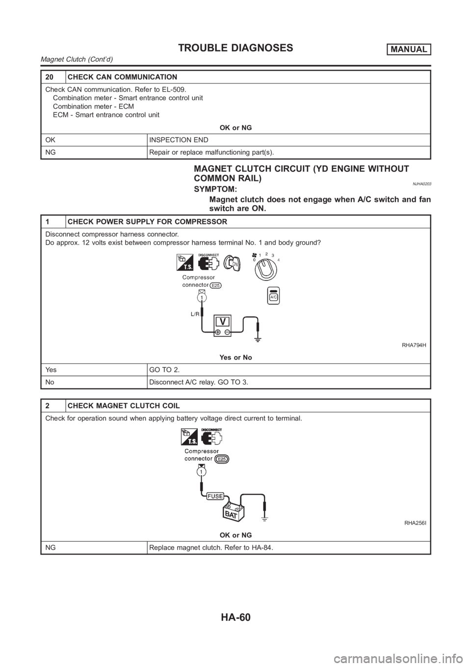
1 CHECK POWER SUPPLY FOR COMPRESSOR
Disconnect compressor harness connector.
Do approx. 12 volts exist between compressor harness terminal No. 1 and body ground?
RHA794H
YesorNo
Ye s G O T O 2 .
No Disconnect A/C relay. GO TO 3.
2 CHECK MAGNET CLUTCH COIL
Check for operation sound when applying battery voltage direct current toterminal.
RHA256I
OK or NG
NG Replace magnet clutch. Refer to HA-84.
TROUBLE DIAGNOSESMANUAL
Magnet Clutch (Cont’d)
HA-60
Page 3035 of 3189
Precautions
SUPPLEMENTAL RESTRAINT SYSTEM (SRS) “AIR BAG” AND “SEAT BELT
PRE-TENSIONER”
NJRS0001The Supplemental Restraint System such as “AIR BAG” and “SEAT BELT PRE-TENSIONER” used along with
a seat belt, helps to reduce the risk or severity of injury to the driver and front passenger for certain types of
collision. The SRS composition which is available to NISSAN MODEL N16 is asfollows (The composition
varies according to the destination and optional equipment.):
For a frontal collision
The Supplemental Restraint System consists of driver’s air bag module (located in the center of the steer-
ing wheel), front passenger air bag module (located on the instrument panel on passenger side), front seat
belt pre-tensioners, a diagnosis sensor unit, warning lamp, wiring harness and spiral cable.
For a side collision
The Supplemental Restraint System consists of front side air bag module (located in the outer side of front
seat), side air bag (satellite) sensor, diagnosis sensor unit (one of components of air bags for a frontal
collision), wiring harness, warning lamp (one of components of air bags for a frontal collision).
WARNING:
To avoid rendering the SRS inoperative, which could increase the risk of personal injury or death
in the event of a collision which would result in air bag inflation, all maintenance should be per-
formed by an authorized NISSAN dealer.
Improper maintenance, including incorrect removal and installation of the SRS, can lead to per-
sonal injury caused by unintentional activation of the system.
Do not use electrical test equipment on any circuit related to the SRS unless instructed to in this
Service Manual. SRS wiring harnesses can be identified by yellow and/or orange harness connec-
tor.
PRECAUTION FOR SEAT BELT SERVICENJRS0002CAUTION:
Before removing the seat belt pre-tensioner assembly, turn the ignition switch off, disconnect both
battery cables and wait at least 3 minutes.
Do not use electrical test equipment for seat belt pre-tensioner connector.
After replacing or reinstalling seat belt pre-tensioner assembly, or reconnecting seat belt pre-ten-
sioner connector, check the system function. Refer to “SRS Operation Check” for details. (RS-49)
Do not disassemble buckle or seat belt assembly.
Replace anchor bolts if they are deformed or worn out.
Never oil tongue and buckle.
If any component of seat belt assembly is questionable, do not repair. Replace the whole seat belt
assembly.
If webbing is cut, frayed, or damaged, replace seat belt assembly.
When replacing seat belt assembly, use a genuine seat belt assembly.
After A CollisionNJRS0002S01WARNING:
Inspect all seat belt assemblies including retractors and attaching hardware after any collision.
NISSAN recommends that all seat belt assemblies in use during a collision be replaced unless the
collision was minor and the belts show no damage and continue to operate properly. Failure to do so
could result in serious personal injury in an accident. Seat belt assemblies not in use during a colli-
sion should also be replaced if either damage or improper operation is noted. Seat belt pre-tensioner
should be replaced even if the seat belts are not in use during a frontal collision in which the air bags
are deployed.
Replace any seat belt assembly (including anchor bolts) if:
The seat belt was in use at the time of a collision (except for minor collisions and the belts, retractors and
buckles show no damage and continue to operate properly).
The seat belt was damaged in an accident. (i.e. torn webbing, bent retractor or guide, etc.)
The seat belt attaching point was damaged in an accident. Inspect the seat belt attaching area for dam-
age or distortion and repair as necessary before installing a new seat beltassembly.
Anchor bolts are deformed or worn out.
GI
MA
EM
LC
EC
FE
CL
MT
AT
AX
SU
BR
ST
BT
HA
SC
EL
IDX
SEAT BELTS
Precautions
RS-3
Page 3052 of 3189
Precautions
SUPPLEMENTAL RESTRAINT SYSTEM (SRS) “AIR BAG” AND “SEAT BELT
PRE-TENSIONER”
NJRS0006The Supplemental Restraint System such as “AIR BAG” and “SEAT BELT PRE-TENSIONER” used along with
a seat belt, helps to reduce the risk or severity of injury to the driver and front passenger for certain types of
collision. The SRS composition which is available to NISSAN MODEL N16 is asfollows (The composition
varies according to the destination and optional equipment.):
For a frontal collision
The Supplemental Restraint System consists of driver’s air bag module (located in the center of the steer-
ing wheel), front passenger air bag module (located on the instrument panel on passenger side), front seat
belt pre-tensioners, a diagnosis sensor unit, warning lamp, wiring harness and spiral cable.
For a side collision
The Supplemental Restraint System consists of front side air bag module (located in the outer side of front
seat), side air bag (satellite) sensor, diagnosis sensor unit (one of components of air bags for a frontal
collision), wiring harness, warning lamp (one of components of air bags for a frontal collision).
WARNING:
To avoid rendering the SRS inoperative, which could increase the risk of personal injury or death
in the event of a collision which would result in air bag inflation, all maintenance should be per-
formed by an authorized NISSAN dealer.
Improper maintenance, including incorrect removal and installation of the SRS, can lead to per-
sonal injury caused by unintentional activation of the system.
Do not use electrical test equipment on any circuit related to the SRS unless instructed to in this
Service Manual. SRS wiring harnesses can be identified by yellow and/or orange harness connec-
tor.
PRECAUTIONS FOR SRS “AIR BAG” AND “SEAT BELT PRE-TENSIONER” SERVICENJRS0007Do not use electrical test equipment to check SRS circuits unless instructed to in this Service Manual.
Before servicing the SRS, turn ignition switch “OFF”, disconnect both battery cables and wait at least 3
minutes.
For approximately 3 minutes after the cables are removed, it is still possible for the air bag and seat belt
pre-tensioner to deploy. Therefore, do not work on any SRS connectors or wires until at least 3 minutes
have passed.
Diagnosis sensor unit must always be installed with their arrow marks “g” pointing towards the front of
the vehicle for proper operation. Also check diagnosis sensor unit for cracks, deformities or rust before
installation and replace as required.
The spiral cable must be aligned with the neutral position since its rotations are limited. Do not attempt to
turn steering wheel or column after removal of steering gear.
Handle air bag module carefully. Always place driver and front passenger air bag modules with the pad
side facing upward and place front side air bag module standing with stud bolt side setting bottom.
Conduct self-diagnosis to check entire SRS for proper function after replacing any components.
After air bag inflates, the front instrument panel assembly should be replaced if damaged.
WIRING DIAGRAMS AND TROUBLE DIAGNOSISNJRS0008When you read wiring diagrams, refer to the following:
GI-12, “HOW TO READ WIRING DIAGRAMS”
EL-12, “POWER SUPPLY ROUTING” for power distribution circuit
When you perform trouble diagnosis, refer to the following:
GI-33, “HOW TO FOLLOW TEST GROUPS IN TROUBLE DIAGNOSES”
GI-22, “HOW TO PERFORM EFFICIENT DIAGNOSES FOR AN ELECTRICAL INCIDENT”
SUPPLEMENTAL RESTRAINT SYSTEM (SRS)
Precautions
RS-20