2003 NISSAN ALMERA N16 transmission
[x] Cancel search: transmissionPage 1981 of 3189
ATC-1
AUTOMATIC AIR CONDITIONER
J AIR CONDITIONER
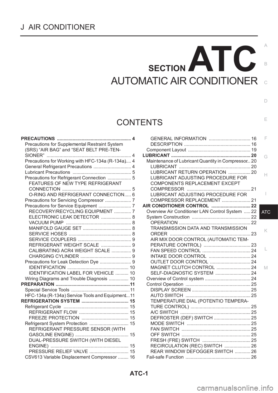
CONTENTS
C
D
E
F
G
H
I
K
L
M
SECTION
A
B
AT C
AUTOMATIC AIR CONDITIONER
PRECAUTIONS .......................................................... 4
Precautions for Supplemental Restraint System
(SRS) “AIR BAG” and “SEAT BELT PRE-TEN-
SIONER” .................................................................. 4
Precautions for Working with HFC-134a (R-134a) ..... 4
General Refrigerant Precautions .............................. 4
Lubricant Precautions .............................................. 5
Precautions for Refrigerant Connection ................... 5
FEATURES OF NEW TYPE REFRIGERANT
CONNECTION ...................................................... 5
O-RING AND REFRIGERANT CONNECTION ..... 6
Precautions for Servicing Compressor ..................... 7
Precautions for Service Equipment .......................... 7
RECOVERY/RECYCLING EQUIPMENT .............. 7
ELECTRONIC LEAK DETECTOR ........................ 8
VACUUM PUMP ................................................... 8
MANIFOLD GAUGE SET ...................................... 8
SERVICE HOSES ................................................. 8
SERVICE COUPLERS .......................................... 9
REFRIGERANT WEIGHT SCALE ........................ 9
CALIBRATING ACR4 WEIGHT SCALE ................ 9
CHARGING CYLINDER ........................................ 9
Precautions for Leak Detection Dye ......................... 9
IDENTIFICATION ................................................ 10
IDENTIFICATION LABEL FOR VEHICLE ........... 10
Wiring Diagrams and Trouble Diagnosis ................ 10
PREPARATION ..........................................................11
Special Service Tools .............................................. 11
HFC-134a (R-134a) Service Tools and Equipment .... 11
REFRIGERATION SYSTEM ..................................... 15
Refrigerant Cycle ................................................... 15
REFRIGERANT FLOW ....................................... 15
FREEZE PROTECTION ..................................... 15
Refrigerant System Protection ............................... 15
REFRIGERANT PRESSURE SENSOR (WITH
GASOLINE ENGINE) .......................................... 15
DUAL-PRESSURE SWITCH (WITH DIESEL
ENGINE) ............................................................. 15
PRESSURE RELIEF VALVE ............................... 15
CSV613 Variable Displacement Compressor ......... 16GENERAL INFORMATION ................................. 16
DESCRIPTION .................................................... 16
Component Layout ................................................. 19
LUBRICANT .............................................................. 20
Maintenance of Lubricant Quantity in Compressor ... 20
LUBRICANT ........................................................ 20
LUBRICANT RETURN OPERATION .................. 20
LUBRICANT ADJUSTING PROCEDURE FOR
COMPONENTS REPLACEMENT EXCEPT
COMPRESSOR .................................................. 21
LUBRICANT ADJUSTING PROCEDURE FOR
COMPRESSOR REPLACEMENT ....................... 21
AIR CONDITIONER CONTROL ............................... 22
Overview Air Conditioner LAN Control System ...... 22
System Construction .............................................. 22
OPERATION ........................................................ 22
TRANSMISSION DATA AND TRANSMISSION
ORDER ............................................................... 23
AIR MIX DOOR CONTROL (AUTOMATIC TEM-
PERATURE CONTROL) ..................................... 23
FAN SPEED CONTROL ...................................... 24
INTAKE DOOR CONTROL ................................. 24
OUTLET DOOR CONTROL ................................ 24
MAGNET CLUTCH CONTROL ........................... 24
SELF-DIAGNOSTIC SYSTEM ............................ 24
Overview of Control system .................................... 24
Control Operation ................................................... 25
DISPLAY SCREEN .............................................. 25
AUTO SWITCH ................................................... 25
TEMPERATURE DIAL (POTENTIO TEMPERA-
TURE CONTROL) ............................................... 25
A/C SWITCH ....................................................... 25
DEFROSTER (DEF) SWITCH ............................. 25
MODE SWITCH .................................................. 25
FAN SWITCH ...................................................... 25
OFF SWITCH ...................................................... 25
FRESH (FRE) SWITCH ...................................... 25
RECIRCULATION (REC) SWITCH ..................... 26
REAR WINDOW DEFOGGER SWITCH ............. 26
Fail-safe Function ................................................... 26
Page 2002 of 3189
ATC-22
AIR CONDITIONER CONTROL
AIR CONDITIONER CONTROL
PFP:27500
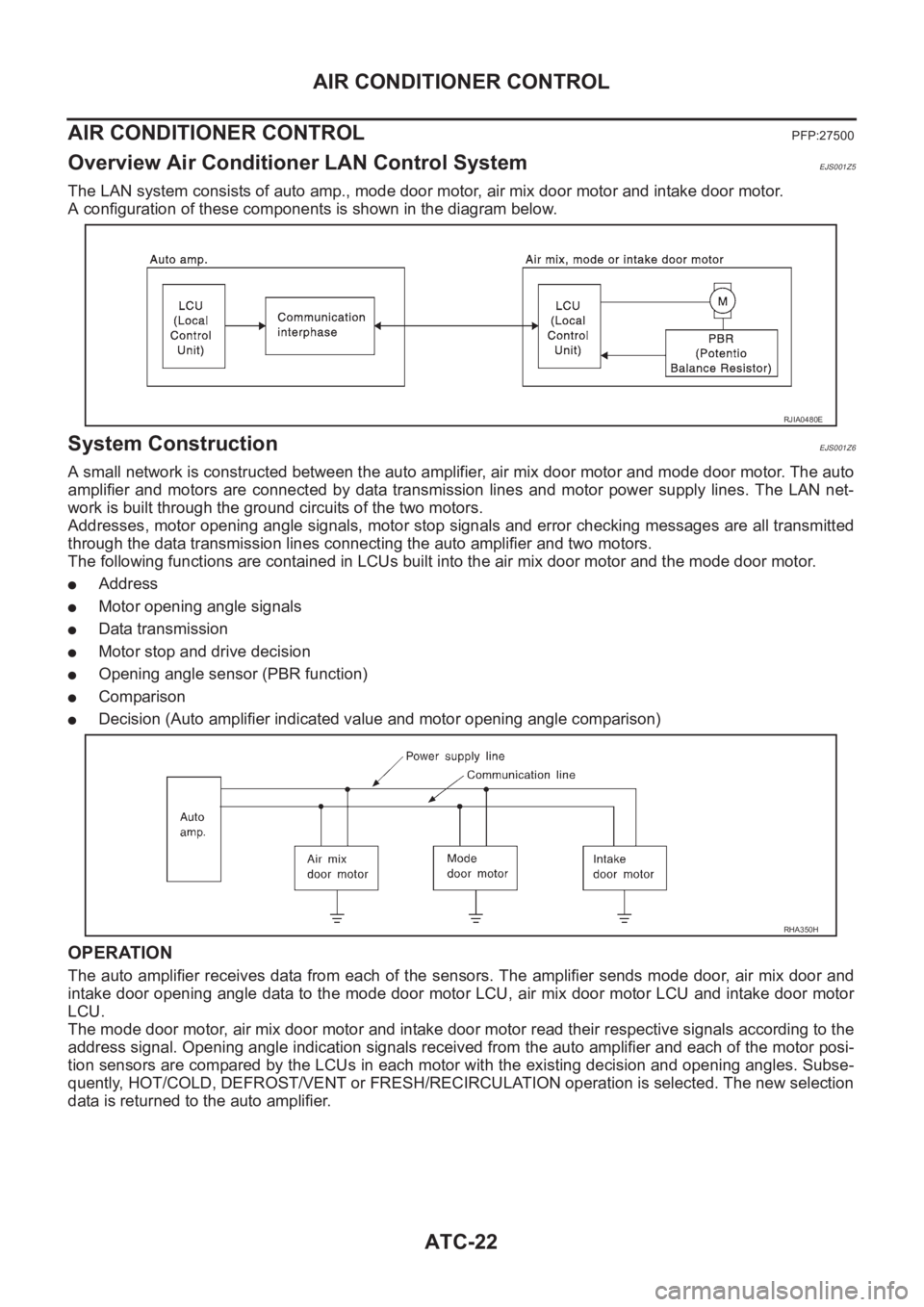
Overview Air Conditioner LAN Control SystemEJS001Z5
The LAN system consists of auto amp., mode door motor, air mix door motor and intake door motor.
A configuration of these components is shown in the diagram below.
System ConstructionEJS001Z6
A small network is constructed between the auto amplifier, air mix door motor and mode door motor. The auto
amplifier and motors are connected by data transmission lines and motor power supply lines. The LAN net-
work is built through the ground circuits of the two motors.
Addresses, motor opening angle signals, motor stop signals and error checking messages are all transmitted
through the data transmission lines connecting the auto amplifier and two motors.
The following functions are contained in LCUs built into the air mix door motor and the mode door motor.
●Address
●Motor opening angle signals
●Data transmission
●Motor stop and drive decision
●Opening angle sensor (PBR function)
●Comparison
●Decision (Auto amplifier indicated value and motor opening angle comparison)
OPERATION
The auto amplifier receives data from each of the sensors. The amplifier sends mode door, air mix door and
intake door opening angle data to the mode door motor LCU, air mix door motor LCU and intake door motor
LCU.
The mode door motor, air mix door motor and intake door motor read their respective signals according to the
address signal. Opening angle indication signals received from the auto amplifier and each of the motor posi-
tion sensors are compared by the LCUs in each motor with the existing decision and opening angles. Subse-
quently, HOT/COLD, DEFROST/VENT or FRESH/RECIRCULATION operation is selected. The new selection
data is returned to the auto amplifier.
RJIA0480E
RHA350H
Page 2003 of 3189
AIR CONDITIONER CONTROL
ATC-23
C
D
E
F
G
H
I
K
L
MA
B
AT C
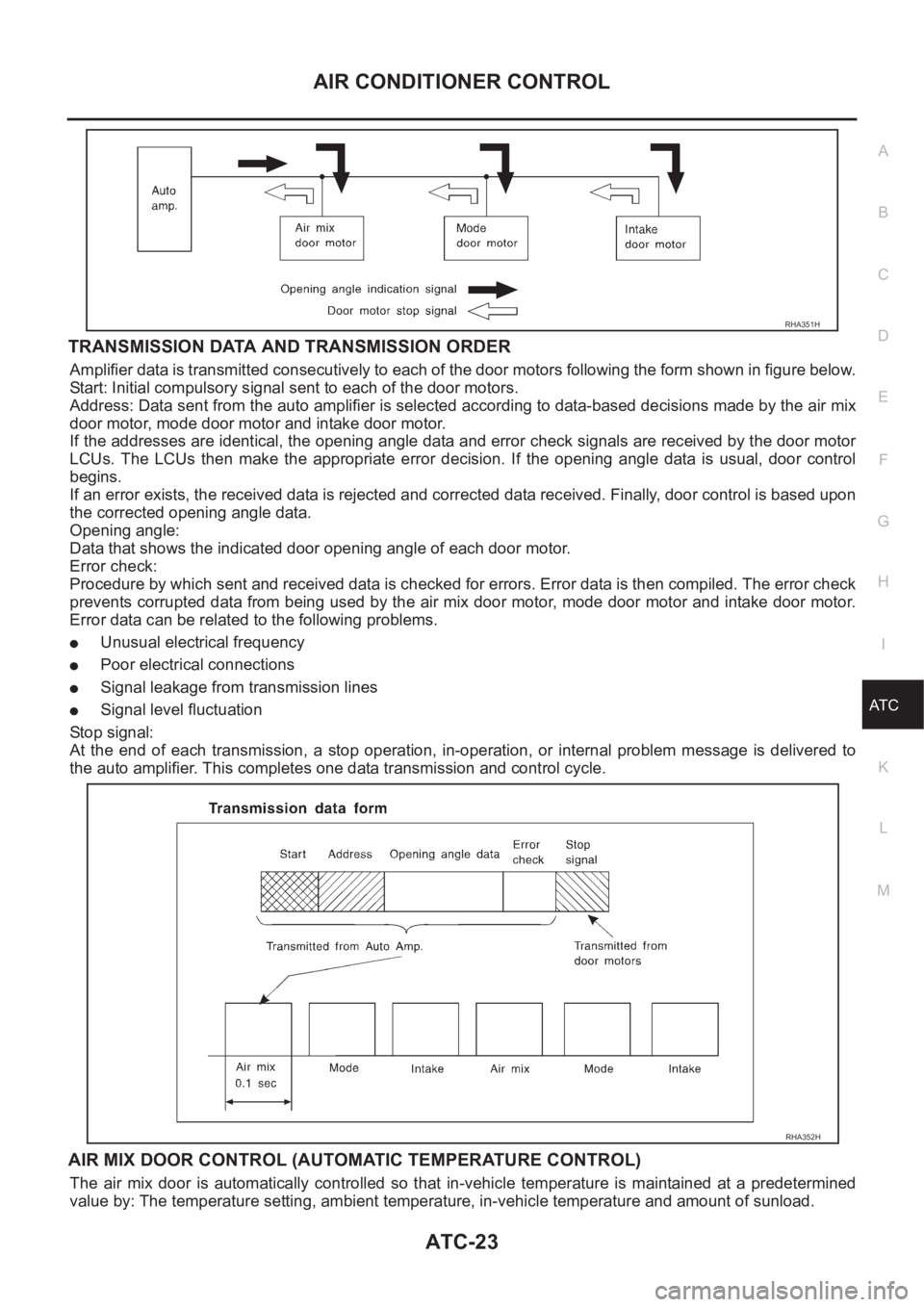
TRANSMISSION DATA AND TRANSMISSION ORDER
Amplifier data is transmitted consecutively to each of the door motors following the form shown in figure below.
Start: Initial compulsory signal sent to each of the door motors.
Address: Data sent from the auto amplifier is selected according to data-based decisions made by the air mix
door motor, mode door motor and intake door motor.
If the addresses are identical, the opening angle data and error check signals are received by the door motor
LCUs. The LCUs then make the appropriate error decision. If the opening angle data is usual, door control
begins.
If an error exists, the received data is rejected and corrected data received. Finally, door control is based upon
the corrected opening angle data.
Opening angle:
Data that shows the indicated door opening angle of each door motor.
Error check:
Procedure by which sent and received data is checked for errors. Error data is then compiled. The error check
prevents corrupted data from being used by the air mix door motor, mode door motor and intake door motor.
Error data can be related to the following problems.
●Unusual electrical frequency
●Poor electrical connections
●Signal leakage from transmission lines
●Signal level fluctuation
Stop signal:
At the end of each transmission, a stop operation, in-operation, or internal problem message is delivered to
the auto amplifier. This completes one data transmission and control cycle.
AIR MIX DOOR CONTROL (AUTOMATIC TEMPERATURE CONTROL)
The air mix door is automatically controlled so that in-vehicle temperature is maintained at a predetermined
value by: The temperature setting, ambient temperature, in-vehicle temperature and amount of sunload.
RHA351H
RHA352H
Page 2179 of 3189
SRA695A
SSU038
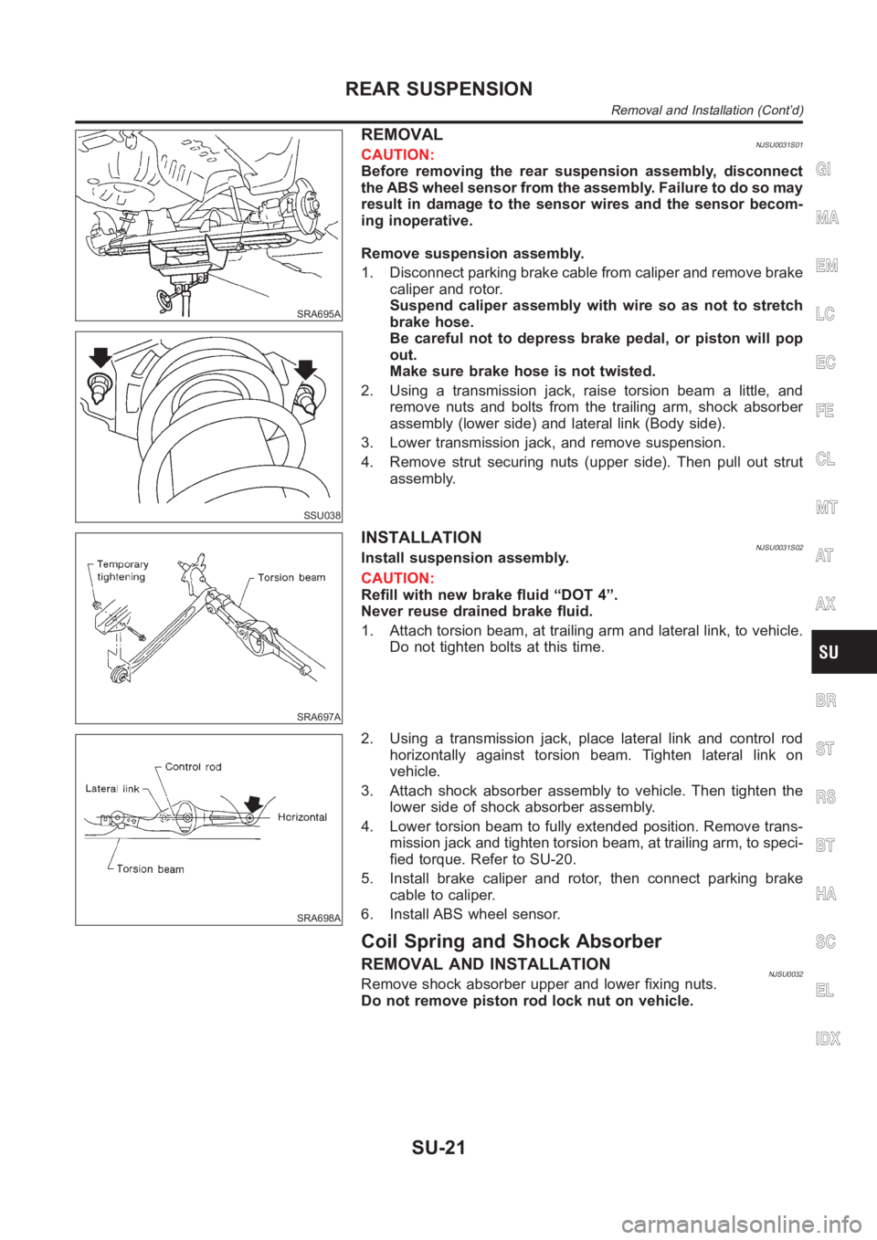
REMOVALNJSU0031S01CAUTION:
Before removing the rear suspension assembly, disconnect
the ABS wheel sensor from the assembly. Failure to do so may
result in damage to the sensor wires and the sensor becom-
ing inoperative.
Remove suspension assembly.
1. Disconnect parking brake cable from caliper and remove brake
caliper and rotor.
Suspend caliper assembly with wire so as not to stretch
brake hose.
Be careful not to depress brake pedal, or piston will pop
out.
Make sure brake hose is not twisted.
2. Using a transmission jack, raise torsion beam a little, and
remove nuts and bolts from the trailing arm, shock absorber
assembly (lower side) and lateral link (Body side).
3. Lower transmission jack, and remove suspension.
4. Remove strut securing nuts (upper side). Then pull out strut
assembly.
SRA697A
INSTALLATIONNJSU0031S02Install suspension assembly.
CAUTION:
Refill with new brake fluid “DOT 4”.
Never reuse drained brake fluid.
1. Attach torsion beam, at trailing arm and lateral link, to vehicle.
Do not tighten bolts at this time.
SRA698A
2. Using a transmission jack, place lateral link and control rod
horizontally against torsion beam. Tighten lateral link on
vehicle.
3. Attach shock absorber assembly to vehicle. Then tighten the
lower side of shock absorber assembly.
4. Lower torsion beam to fully extended position. Remove trans-
mission jack and tighten torsion beam, at trailing arm, to speci-
fied torque. Refer to SU-20.
5. Install brake caliper and rotor, then connect parking brake
cable to caliper.
6. Install ABS wheel sensor.
Coil Spring and Shock Absorber
REMOVAL AND INSTALLATIONNJSU0032Remove shock absorber upper and lower fixing nuts.
Do not remove piston rod lock nut on vehicle.
GI
MA
EM
LC
EC
FE
CL
MT
AT
AX
BR
ST
RS
BT
HA
SC
EL
IDX
REAR SUSPENSION
Removal and Installation (Cont’d)
SU-21
Page 2459 of 3189
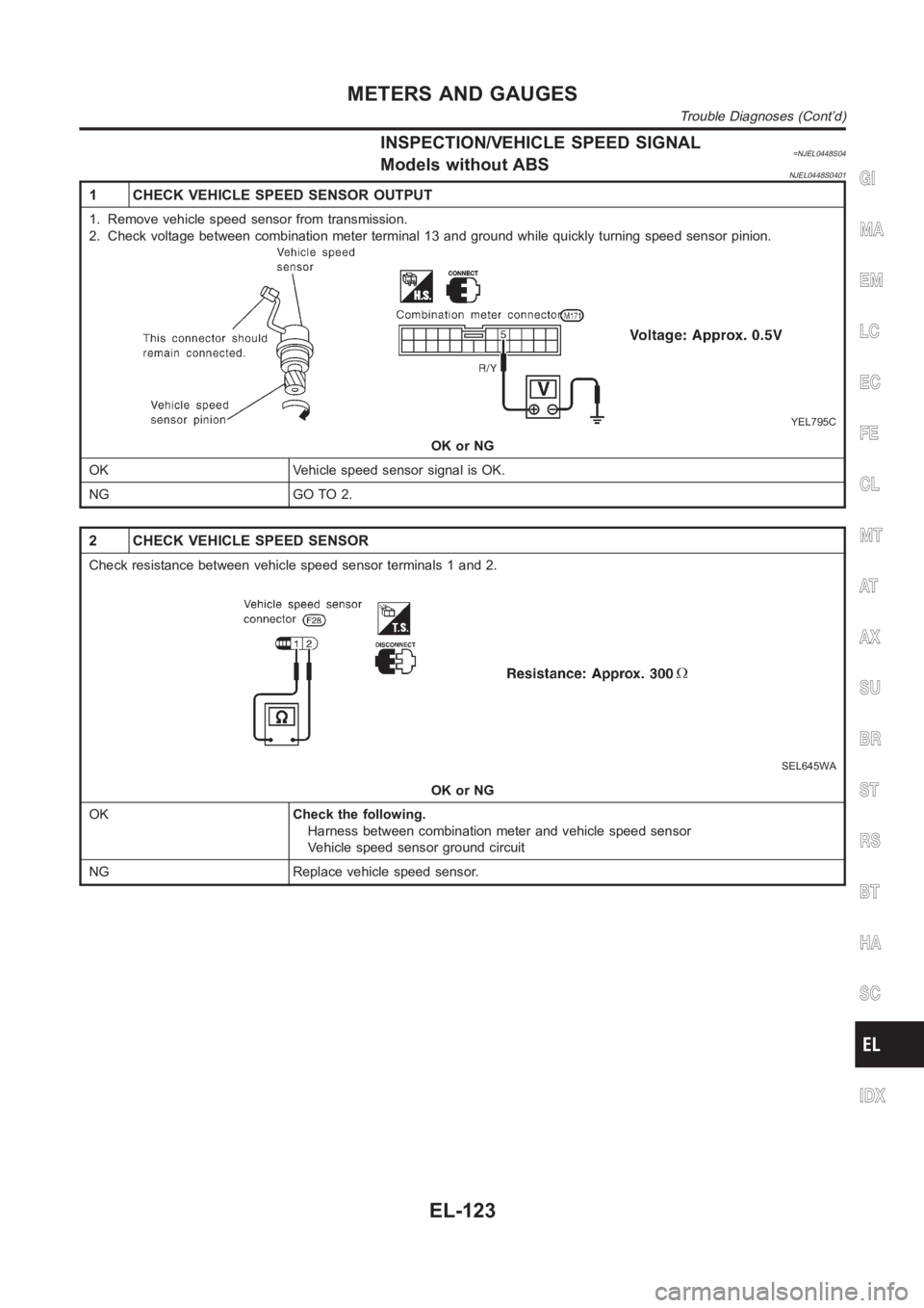
INSPECTION/VEHICLE SPEED SIGNAL=NJEL0448S04Models without ABSNJEL0448S0401
1 CHECK VEHICLE SPEED SENSOR OUTPUT
1. Remove vehicle speed sensor from transmission.
2. Check voltage between combination meter terminal 13 and ground while quickly turning speed sensor pinion.
YEL795C
OK or NG
OK Vehicle speed sensor signal is OK.
NG GO TO 2.
2 CHECK VEHICLE SPEED SENSOR
Check resistance between vehicle speed sensor terminals 1 and 2.
SEL645WA
OK or NG
OKCheck the following.
Harness between combination meter and vehicle speed sensor
Vehicle speed sensor ground circuit
NG Replace vehicle speed sensor.
GI
MA
EM
LC
EC
FE
CL
MT
AT
AX
SU
BR
ST
RS
BT
HA
SC
IDX
METERS AND GAUGES
Trouble Diagnoses (Cont’d)
EL-123
Page 2464 of 3189
SEL498X
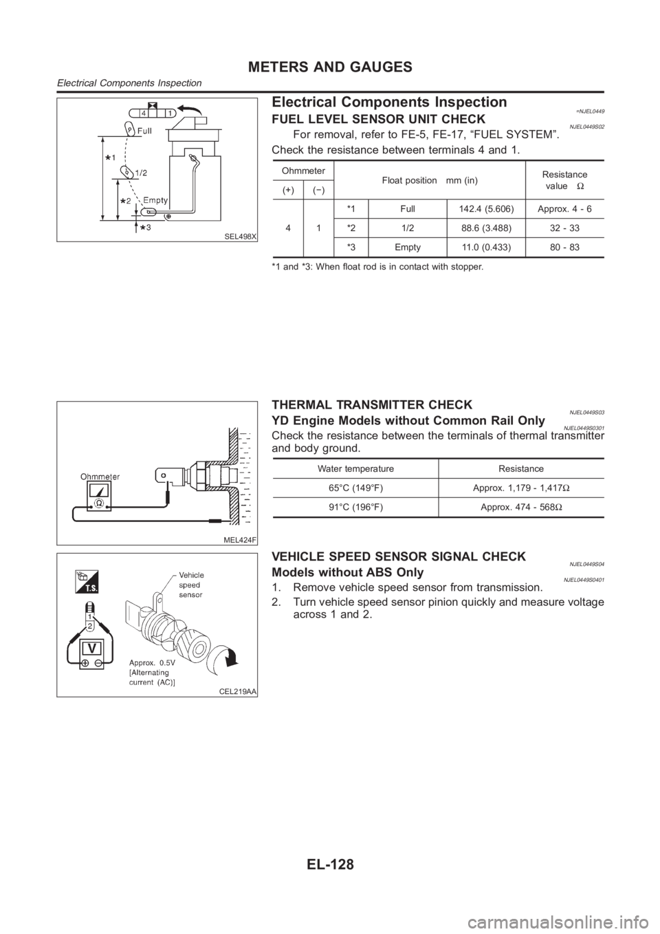
Electrical Components Inspection=NJEL0449FUEL LEVEL SENSOR UNIT CHECKNJEL0449S02For removal, refer to FE-5, FE-17, “FUEL SYSTEM”.
Check the resistance between terminals 4 and 1.
Ohmmeter
Float position mm (in)Resistance
valueΩ
(+) (−)
41*1 Full 142.4 (5.606) Approx. 4 - 6
*2 1/2 88.6 (3.488) 32 - 33
*3 Empty 11.0 (0.433) 80 - 83
*1 and *3: When float rod is in contact with stopper.
MEL424F
THERMAL TRANSMITTER CHECKNJEL0449S03YD Engine Models without Common Rail OnlyNJEL0449S0301Check the resistance between the terminals of thermal transmitter
and body ground.
Water temperature Resistance
65°C (149°F) Approx. 1,179 - 1,417Ω
91°C (196°F) Approx. 474 - 568Ω
CEL219AA
VEHICLE SPEED SENSOR SIGNAL CHECKNJEL0449S04Models without ABS OnlyNJEL0449S04011. Remove vehicle speed sensor from transmission.
2. Turn vehicle speed sensor pinion quickly and measure voltage
across 1 and 2.
METERS AND GAUGES
Electrical Components Inspection
EL-128
Page 2477 of 3189
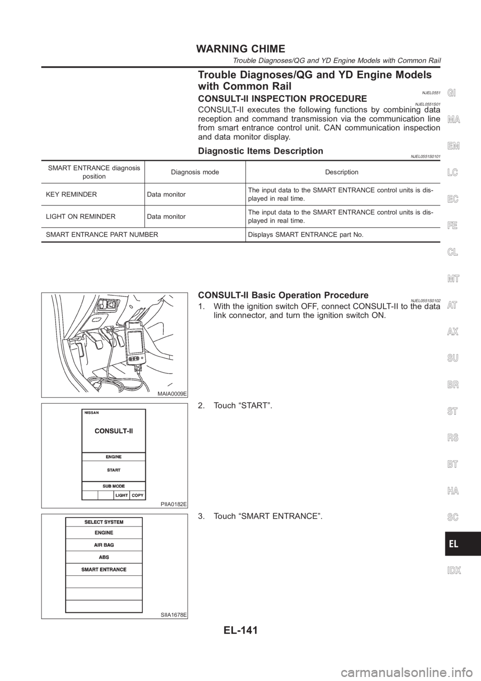
Trouble Diagnoses/QG and YD Engine Models
with Common Rail
NJEL0551CONSULT-II INSPECTION PROCEDURENJEL0551S01CONSULT-II executes the following functions by combining data
reception and command transmission via the communication line
from smart entrance control unit. CAN communication inspection
and data monitor display.
Diagnostic Items DescriptionNJEL0551S0101
SMART ENTRANCE diagnosis
positionDiagnosis mode Description
KEY REMINDER Data monitorThe input data to the SMART ENTRANCE control units is dis-
played in real time.
LIGHT ON REMINDER Data monitorThe input data to the SMART ENTRANCE control units is dis-
played in real time.
SMART ENTRANCE PART NUMBER Displays SMART ENTRANCE part No.
MAIA0009E
CONSULT-II Basic Operation ProcedureNJEL0551S01021. With the ignition switch OFF, connect CONSULT-II to the data
link connector, and turn the ignition switch ON.
PIIA0182E
2. Touch “START”.
SIIA1678E
3. Touch “SMART ENTRANCE”.
GI
MA
EM
LC
EC
FE
CL
MT
AT
AX
SU
BR
ST
RS
BT
HA
SC
IDX
WARNING CHIME
Trouble Diagnoses/QG and YD Engine Models with Common Rail
EL-141
Page 2801 of 3189
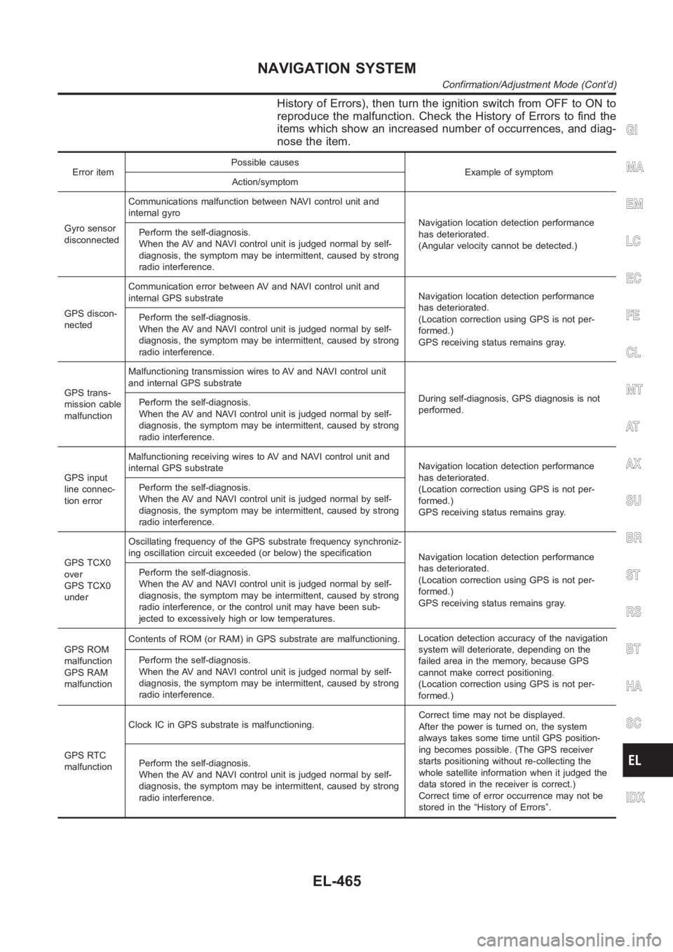
History of Errors), then turn the ignition switch from OFF to ON to
reproduce the malfunction. Check the History of Errors to find the
items which show an increased number of occurrences, and diag-
nose the item.
Error itemPossible causes
Example of symptom
Action/symptom
Gyro sensor
disconnectedCommunications malfunction between NAVI control unit and
internal gyro
Navigation location detection performance
has deteriorated.
(Angular velocity cannot be detected.) Perform the self-diagnosis.
When the AV and NAVI control unit is judged normal by self-
diagnosis, the symptom may be intermittent, caused by strong
radio interference.
GPS discon-
nectedCommunication error between AV and NAVI control unit and
internal GPS substrateNavigation location detection performance
has deteriorated.
(Location correction using GPS is not per-
formed.)
GPS receiving status remains gray. Perform the self-diagnosis.
When the AV and NAVI control unit is judged normal by self-
diagnosis, the symptom may be intermittent, caused by strong
radio interference.
GPS trans-
mission cable
malfunctionMalfunctioning transmission wires to AV and NAVI control unit
and internal GPS substrate
During self-diagnosis, GPS diagnosis is not
performed. Perform the self-diagnosis.
When the AV and NAVI control unit is judged normal by self-
diagnosis, the symptom may be intermittent, caused by strong
radio interference.
GPS input
line connec-
tion errorMalfunctioning receiving wires to AV and NAVI control unit and
internal GPS substrateNavigation location detection performance
has deteriorated.
(Location correction using GPS is not per-
formed.)
GPS receiving status remains gray. Perform the self-diagnosis.
When the AV and NAVI control unit is judged normal by self-
diagnosis, the symptom may be intermittent, caused by strong
radio interference.
GPS TCX0
over
GPS TCX0
underOscillating frequency of the GPS substrate frequency synchroniz-
ing oscillation circuit exceeded (or below) the specification
Navigation location detection performance
has deteriorated.
(Location correction using GPS is not per-
formed.)
GPS receiving status remains gray. Perform the self-diagnosis.
When the AV and NAVI control unit is judged normal by self-
diagnosis, the symptom may be intermittent, caused by strong
radio interference, or the control unit may have been sub-
jected to excessively high or low temperatures.
GPS ROM
malfunction
GPS RAM
malfunctionContents of ROM (or RAM) in GPS substrate are malfunctioning.Location detection accuracy of the navigation
system will deteriorate, depending on the
failed area in the memory, because GPS
cannot make correct positioning.
(Location correction using GPS is not per-
formed.) Perform the self-diagnosis.
When the AV and NAVI control unit is judged normal by self-
diagnosis, the symptom may be intermittent, caused by strong
radio interference.
GPS RTC
malfunctionClock IC in GPS substrate is malfunctioning.Correct time may not be displayed.
After the power is turned on, the system
always takes some time until GPS position-
ing becomes possible. (The GPS receiver
starts positioning without re-collecting the
whole satellite information when it judged the
data stored in the receiver is correct.)
Correct time of error occurrence may not be
stored in the “History of Errors”. Perform the self-diagnosis.
When the AV and NAVI control unit is judged normal by self-
diagnosis, the symptom may be intermittent, caused by strong
radio interference.
GI
MA
EM
LC
EC
FE
CL
MT
AT
AX
SU
BR
ST
RS
BT
HA
SC
IDX
NAVIGATION SYSTEM
Confirmation/Adjustment Mode (Cont’d)
EL-465