2003 NISSAN ALMERA N16 transmission
[x] Cancel search: transmissionPage 2845 of 3189

System DescriptionNJEL0535CAN (Controller Area Network) is a serial communication line for real timeapplication. It is an on-vehicle mul-
tiplex communication line with high data communication speed and excellent error detection ability. Many
electronic control units are equipped onto a vehicle, and each control unit shares information and links with
other control units during operation (not independent). In CAN communication, control units are connected with
2 communication lines (CAN H line, CAN L line) allowing a high rate of information transmission with less wir-
ing. Each control unit transmits/receives data but selectively reads requireddataonly.
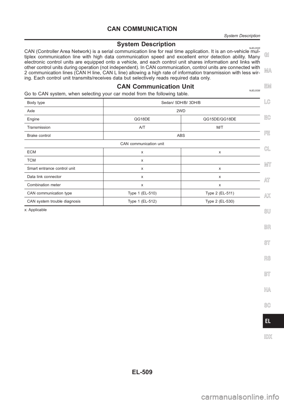
CAN Communication UnitNJEL0536Go to CAN system, when selecting your car model from the following table.
Body type Sedan/ 5DH/B/ 3DH/B
Axle2WD
Engine QG18DE QG15DE/QG18DE
Transmission A/T M/T
Brake controlABS
CAN communication unit
ECM x x
TCM x
Smart entrance control unit x x
Data link connector x x
Combination meter x x
CAN communication type Type 1 (EL-510) Type 2 (EL-511)
CAN system trouble diagnosis Type 1 (EL-512) Type 2 (EL-530)
x: Applicable
GI
MA
EM
LC
EC
FE
CL
MT
AT
AX
SU
BR
ST
RS
BT
HA
SC
IDX
CAN COMMUNICATION
System Description
EL-509
Page 2848 of 3189

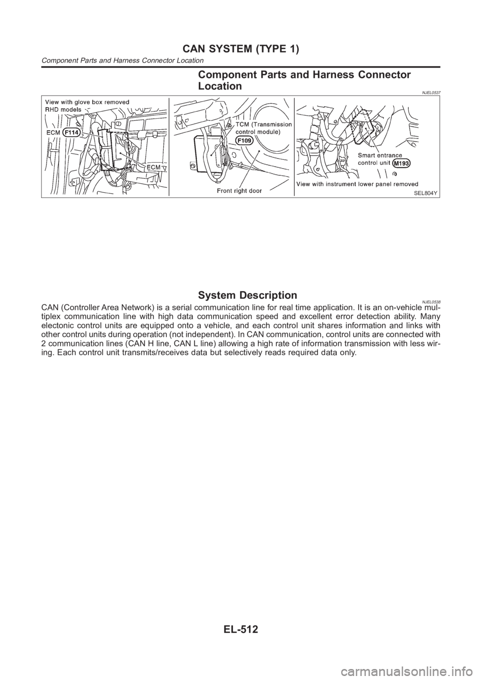
Component Parts and Harness Connector
Location
NJEL0537
SEL804Y
System DescriptionNJEL0538CAN (Controller Area Network) is a serial communication line for real timeapplication. It is an on-vehicle mul-
tiplex communication line with high data communication speed and excellent error detection ability. Many
electonic control units are equipped onto a vehicle, and each control unitshares information and links with
other control units during operation (not independent). In CAN communication, control units are connected with
2 communication lines (CAN H line, CAN L line) allowing a high rate of information transmission with less wir-
ing. Each control unit transmits/receives data but selectively reads requireddataonly.
CAN SYSTEM (TYPE 1)
Component Parts and Harness Connector Location
EL-512
Page 2866 of 3189

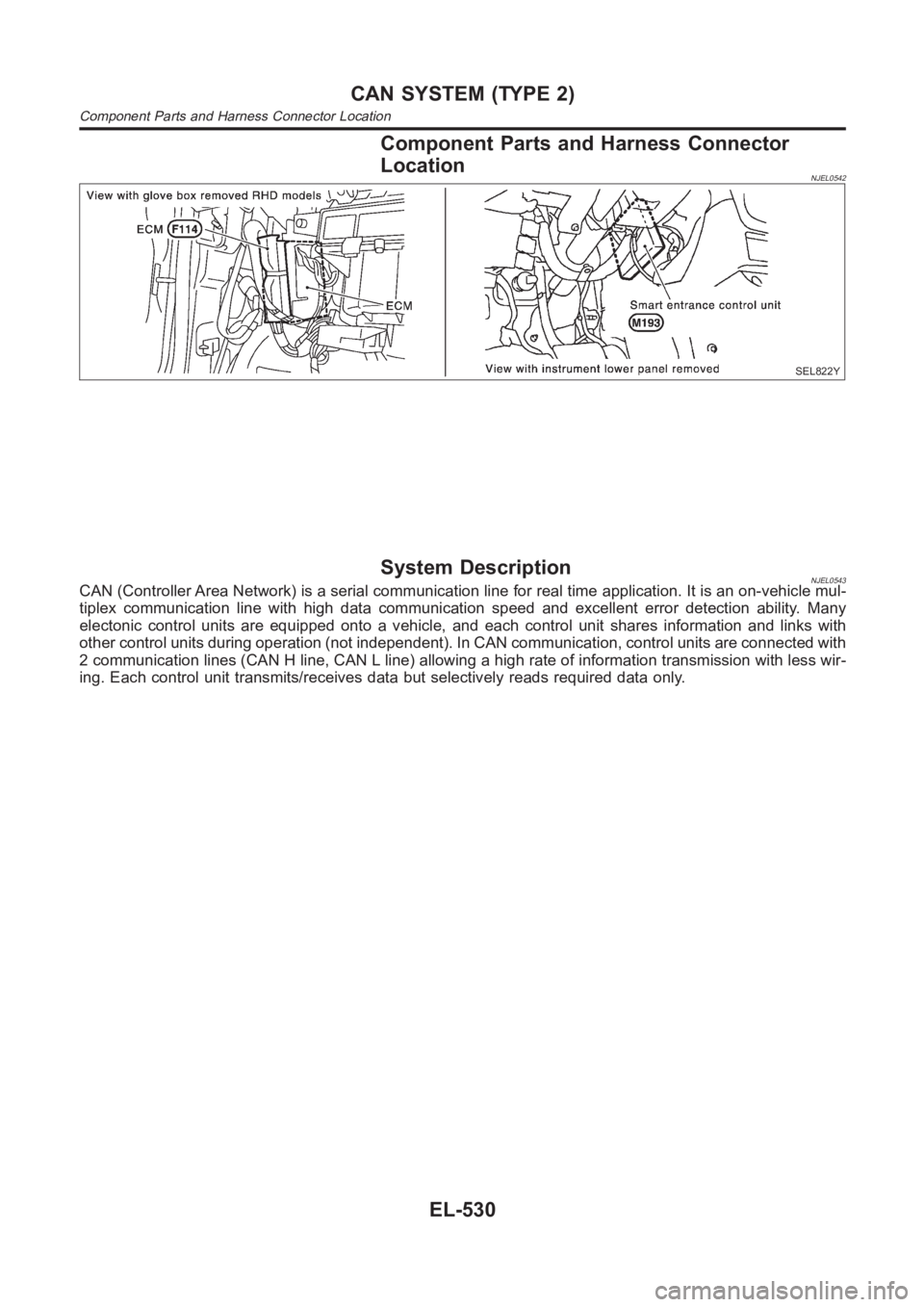
Component Parts and Harness Connector
Location
NJEL0542
SEL822Y
System DescriptionNJEL0543CAN (Controller Area Network) is a serial communication line for real timeapplication. It is an on-vehicle mul-
tiplex communication line with high data communication speed and excellent error detection ability. Many
electonic control units are equipped onto a vehicle, and each control unitshares information and links with
other control units during operation (not independent). In CAN communication, control units are connected with
2 communication lines (CAN H line, CAN L line) allowing a high rate of information transmission with less wir-
ing. Each control unit transmits/receives data but selectively reads requireddataonly.
CAN SYSTEM (TYPE 2)
Component Parts and Harness Connector Location
EL-530
Page 3183 of 3189

Starting system...............................................SC-13
Steering linkage ..............................................ST-15
Steering switch................................................EL-41
Steering wheel and column ............................ST-10
Steering wheel play ..........................................ST-6
Steering wheel turning force .............................ST-8
Stop lamp switch (QG engine) ......EC-361, EC-630
Stop lamp <0011001100110011001100110011001100110011001100110011001100110011001100110011001100110011001100110011001100110011001100110011001100110011001100110011001100110011001100110011001100110011001100110011001100
110011001100110011[.EL-58
STOP/L - Wiring diagram................................EL-58
Striking rod (M/T) ...............................MT-32, 56, 94
Strut (front) <0011001100110011001100110011001100110011001100110011001100110011001100110011001100110011001100110011001100110011001100110011001100110011001100110011001100110011001100110011001100110011001100110011001100
11[....SU-9
Strut (rear) <0011001100110011001100110011001100110011001100110011001100110011001100110011001100110011001100110011001100110011001100110011001100110011001100110011001100110011001100110011001100110011001100110011001100
110011[..SU-20
Sub-gear (M/T) .........................................MT-31, 55
Sun roof, electric ...........................................EL-249
Sunload sensor...........ATC-106, ATC-108, ATC-118
Sunroof<0011001100110011001100110011001100110011001100110011001100110011001100110011001100110011001100110011001100110011001100110011001100110011001100110011001100110011001100110011001100110011001100110011001100
1100110011001100110011[....BT-60
Super lock <0011001100110011001100110011001100110011001100110011001100110011001100110011001100110011001100110011001100110011001100110011001100110011001100110011001100110011001100110011001100110011001100110011001100
11001100110028[L-301
Supplemental restraint system - Wiring
diagram <0011001100110011001100110011001100110011001100110011001100110011001100110011001100110011001100110011001100110011001100110011001100110011001100110011001100110011001100110011001100110011001100110011001100
1100110011001100110035[S-46
Supplemental Restraint System .....................RS-20
Symbols and abbreviations..............................GI-11
Symptom matrix chart
(QG engine)..................................EC-70, EC-449
Symptom matrix chart (YD engine)................EC-53
Synchronizer (M/T) ............................MT-31, 55, 93
System readiness test (SRT) code
(QG engine) ................................................EC-40
T
Tachometer <0011001100110011001100110011001100110011001100110011001100110011001100110011001100110011001100110011001100110011001100110011001100110011001100110011001100110011001100110011001100110011001100110011001100
1100110028[L-110
Tail lamp <0011001100110011001100110011001100110011001100110011001100110011001100110011001100110011001100110011001100110011001100110011001100110011001100110011001100110011001100110011001100110011001100110011001100
110011001100110011[...EL-55
TCM circuit diagram ........................................AT-15
TCM inspection table .......................AT-107, AT-303
Thermostat................................................LC-15,40
Three way catalyst function
(QG engine) ..............................................EC-247
Three way catalyst precautions.........................GI-6
Throttle body (QG engine) .............................EM-18
Throttle control motor relay
(QG engine)................................EC-286, EC-587
Throttle position sensor (TPS)
(QG engine) ..EC-200, EC-206, EC-336, EC-342,
EC-344, EC-526, EC-532, EC-609,
EC-615, EC-617
Throttle position switch ....................AT-244, AT-340
Throttle valve closed position learning
(QG engine)..................................EC-31, EC-426
Throwout bearing - See Clutch release
bearing ..................................................CL-17,20
Tie-rod ball joints.............................................ST- 1 9
Tie-rod <0011001100110011001100110011001100110011001100110011001100110011001100110011001100110011001100110011001100110011001100110011001100110011001100110011001100110011001100110011001100110011001100110011001100
1100110011001100110011[.....ST-15
Tightening torque of standard bolts.................GI-50
Timing chain (QG engine)..............................EM-47
Timing chain (YD engine) ..............................EM-20
Tire size <0011001100110011001100110011001100110011001100110011001100110011001100110011001100110011001100110011001100110011001100110011001100110011001100110011001100110011001100110011001100110011001100110011001100
110011001100110011[....GI-44
Torque converter installation ............AT-412, AT-509
Tow truck towing ..............................................GI-48
TPS1 - Wiring diagram
(QG engine)................................EC-208, EC-534TPS2 - Wiring diagram
(QG engine) ................................EC-338, EC-611
TPS3 - Wiring diagram
(QG engine)................................EC-202, EC-528
Transmission case (M/T) ...................MT-30, 54, 92
Tread-FR&RR (Dimensions)............................GI-44
Trim <0011001100110011001100110011001100110011001100110011001100110011001100110011001100110011001100110011001100110011001100110011001100110011001100110011001100110011001100110011001100110011001100110011001100
1100110011001100110011001100110011[......BT-31
Trouble diagnoses ...........................................GI-32
Trunk lid finisher..............................................BT- 4 5
Trunk lid opener - See Trunk lid .....................BT-10
Trunk lid trim <0011001100110011001100110011001100110011001100110011001100110011001100110011001100110011001100110011001100110011001100110011001100110011001100110011001100110011001100110011001100110011001100110011001100
11[BT-45
Trunk lid <0011001100110011001100110011001100110011001100110011001100110011001100110011001100110011001100110011001100110011001100110011001100110011001100110011001100110011001100110011001100110011001100110011001100
110011001100110011[...BT-10
Trunk room lamp ...........................................EL-108
Trunk room trim...............................................BT-45
TURN - Wiring diagram ..................................EL-71
Turn signal lamp .............................................EL-67
Two trip detection logic
(QG engine)..................................EC-36, EC-430
Two-pole lift <0011001100110011001100110011001100110011001100110011001100110011001100110011001100110011001100110011001100110011001100110011001100110011001100110011001100110011001100110011001100110011001100110011001100
11[..GI-47
U
Under body <0011001100110011001100110011001100110011001100110011001100110011001100110011001100110011001100110011001100110011001100110011001100110011001100110011001100110011001100110011001100110011001100110011001100
11001100110025[T- 7 7
V
Vacuum hose (brake system).........................BR-22
Vacuum hose drawing (Engine control)
(QG engine)..................................EC-22, EC-417
Vacuum pump.................................................BR-23
Valve clearance (YD engine) .........................EM-59
Valve guide (QG engine) ...............................EM-63
Valve guide (YD engine) ................................EM-50
Valve lifter<0011001100110011001100110011001100110011001100110011001100110011001100110011001100110011001100110011001100110011001100110011001100110011001100110011001100110011001100110011001100110011001100110011001100
110011[...EM-41
Valve seat (QG engine) .................................EM-64
Valve seat (YD engine) ..................................EM-52
Valve spring (QG engine) ..............................EM-66
Valve spring (YD engine) ...............................EM-54
Vehicle speed sensor (VSS)
(QG engine)................................EC-258, EC-679
Vehicle speed sensor (VSS)
(YD engine)...............................................EC-105
Ventilation air filter (manual A/C) ...................HA-95
Ventilation air filter ......................................ATC-129
Viscosity number (SAE) .................................MA-20
Viscous coupling (FF M/T) .............................MT-93
VSS - Wiring diagram (YD engine) ..............EC-105
W
WARN - Wiring diagram ...............................EL-130
Warning chime ..............................................EL-136
Warning lamps ..............................................EL-129
Washer, front .................................................EL-158
Water pump ..............................................LC-14, 38
Water temperature gauge .............................EL-110
Weatherstrip - See Exterior ............................BT-47
GI
MA
EM
LC
EC
FE
CL
MT
AT
AX
SU
BR
ST
RS
BT
HA
SC
EL
ALPHABETICAL INDEX
IDX-9