Page 1 of 4500
LS430 SPECIFICATIONS INDEX
SystemSpecification/Procedure
Air Conditioning
ServiceSERVICE DATA
TorqueTORQUE SPECIFICATION
Axle Nut/Hub Nut
Front69 N.m (700 kgf.cm, 51 ft.lbf)
Rear290 N.m (2,960 kgf.cm, 214 ft.lbf)
BatteryNA
Brakes
Bleeding
SequenceBLEEDING
Disc BrakesSERVICE DATA
TorqueTORQUE SPECIFICATION
Charging
GeneratorSERVICE DATA
TorqueTORQUE SPECIFICATION
Drive Belts
AdjustmentREPLACEMENT
Belt RoutingDRIVE BELT
Engine Cooling
General Service
SpecificationsSERVICE DATA
Radiator Cap
PressureStandard Value
93 to 123 kPa (0.95 to 1.25 kgf/cm
2 , 13.5 to 17.8 psi)
Minimum Standard Value
78 kPa (0.8 kgf/cm
2 , 11.4 psi)
Thermostat R & ITHERMOSTAT
Water Pump R &
IWATER PUMP
Engine Mechanical
CompressionSERVICE DATA
Oil Pressureat idle, 29 kPa (0.3 kgf.cm2 , 43 psi) or more
at 3,000 rpm, 294 to 588 kPa (3.0 to 6.0 kgf.cm
2 , 43 to 85 psi)
OverhaulSERVICE DATA
TorqueTORQUE SPECIFICATION
Page 2635 of 4500
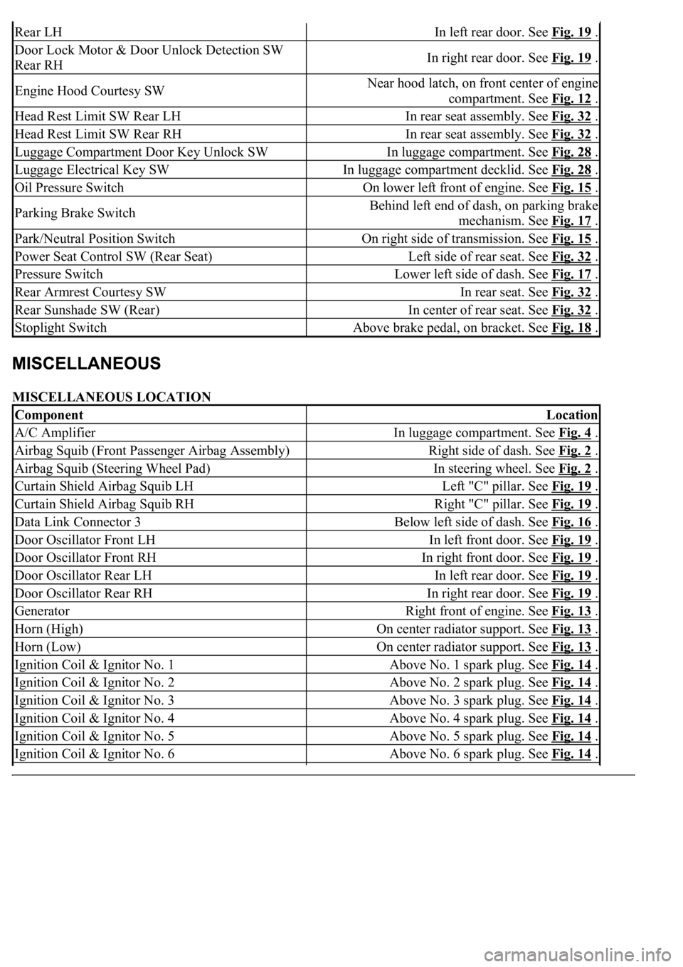
MISCELLANEOUS LOCATION
Rear LHIn left rear door. See Fig. 19 .
Door Lock Motor & Door Unlock Detection SW
Rear RHIn right rear door. See Fig. 19 .
Engine Hood Courtesy SWNear hood latch, on front center of engine
compartment. See Fig. 12
.
Head Rest Limit SW Rear LHIn rear seat assembly. See Fig. 32 .
Head Rest Limit SW Rear RHIn rear seat assembly. See Fig. 32 .
Luggage Compartment Door Key Unlock SWIn luggage compartment. See Fig. 28 .
Luggage Electrical Key SWIn luggage compartment decklid. See Fig. 28 .
Oil Pressure SwitchOn lower left front of engine. See Fig. 15 .
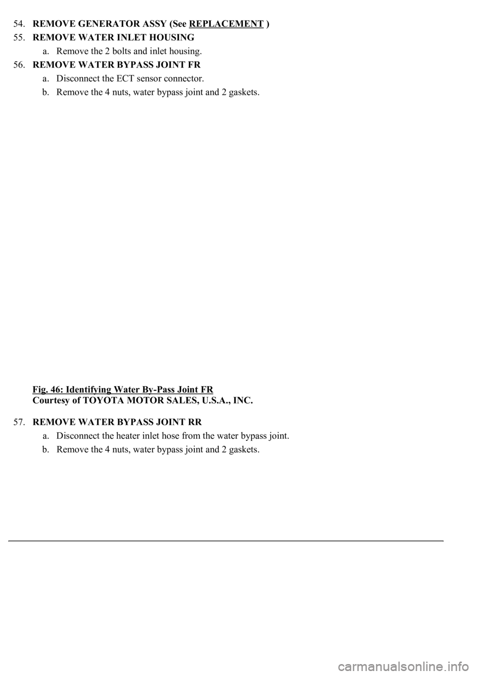
Parking Brake SwitchBehind left end of dash, on parking brake
mechanism. See Fig. 17
.
Park/Neutral Position SwitchOn right side of transmission. See Fig. 15 .
Power Seat Control SW (Rear Seat)Left side of rear seat. See Fig. 32 .
Pressure SwitchLower left side of dash. See Fig. 17 .
Rear Armrest Courtesy SWIn rear seat. See Fig. 32 .
Rear Sunshade SW (Rear)In center of rear seat. See Fig. 32 .
Stoplight SwitchAbove brake pedal, on bracket. See Fig. 18 .
ComponentLocation
A/C AmplifierIn luggage compartment. See Fig. 4 .
Airbag Squib (Front Passenger Airbag Assembly)Right side of dash. See Fig. 2 .
Airbag Squib (Steering Wheel Pad)In steering wheel. See Fig. 2 .
Curtain Shield Airbag Squib LHLeft "C" pillar. See Fig. 19 .
Curtain Shield Airbag Squib RHRight "C" pillar. See Fig. 19 .
Data Link Connector 3Below left side of dash. See Fig. 16 .
Door Oscillator Front LHIn left front door. See Fig. 19 .
Door Oscillator Front RHIn right front door. See Fig. 19 .
Door Oscillator Rear LHIn left rear door. See Fig. 19 .
Door Oscillator Rear RHIn right rear door. See Fig. 19 .
GeneratorRight front of engine. See Fig. 13 .
Horn (High)On center radiator support. See Fig. 13 .
Horn (Low)On center radiator support. See Fig. 13 .
Ignition Coil & Ignitor No. 1Above No. 1 spark plug. See Fig. 14 .
Ignition Coil & Ignitor No. 2Above No. 2 spark plug. See Fig. 14 .
Ignition Coil & Ignitor No. 3Above No. 3 spark plug. See Fig. 14 .
Ignition Coil & Ignitor No. 4Above No. 4 spark plug. See Fig. 14 .
Ignition Coil & Ignitor No. 5Above No. 5 spark plug. See Fig. 14 .
Ignition Coil & Ignitor No. 6Above No. 6 spark plug. See Fig. 14 .
Page 3279 of 4500
INSPECTION
1.INSPECT ENGINE COOLANT (See REPLACEMENT
)
2.INSPECT ENGINE OIL (See ON
-VEHICLE INSPECTION )
3.INSPECT BATTERY (See REPLACEMENT
)
4.INSPECT AIR CLEANER FILTER ELEMENT SUB-ASSY
5.INSPECT SPARK PLUG (See REPLACEMENT
)
6.INSPECT FAN AND GENERATOR V BELT
HINT:
Use of the automatic tensioner has made tension and flexibility measurements unnecessary.
a. Check that the indicator mark on the automatic tensioner is within range A as shown in the
illustration.
b. When the mark is out of the standard range, replace the V belt with a new one.
Page 3287 of 4500
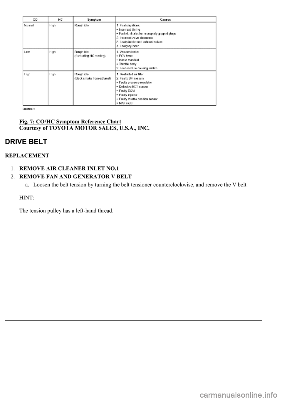
Fig. 7: CO/HC Symptom Reference Chart
Courtesy of TOYOTA MOTOR SALES, U.S.A., INC.
REPLACEMENT
1.REMOVE AIR CLEANER INLET NO.1
2.REMOVE FAN AND GENERATOR V BELT
a. Loosen the belt tension by turning the belt tensioner counterclockwise, and remove the V belt.
HINT:
The tension pulle
y has a left-hand thread.
Page 3288 of 4500
Fig. 8: Removing Fan And Generator V Belt
Courtesy of TOYOTA MOTOR SALES, U.S.A., INC.
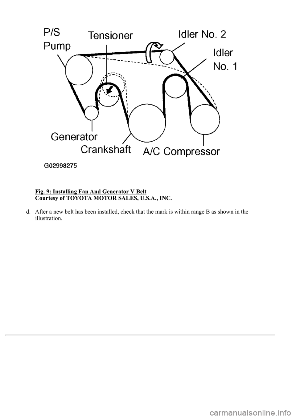
3.INSTALL FAN AND GENERATOR V BELT
a. Set the V belt to everything except the idler pulley No. 2, as shown in the illustration.
b. Loosen the V belt by turning the belt tensioner counterclockwise.
c. Then set the V belt to the idler pulle
y.
Page 3289 of 4500
Fig. 9: Installing Fan And Generator V Belt
Courtesy of TOYOTA MOTOR SALES, U.S.A., INC.
d. After a new belt has been installed, check that the mark is within range B as shown in the
illustration.
Page 3313 of 4500
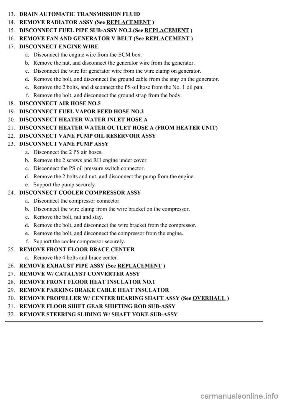
13.DRAIN AUTOMATIC TRANSMISSION FLUID
14.REMOVE RADIATOR ASSY (See REPLACEMENT
)
15.DISCONNECT FUEL PIPE SUB-ASSY NO.2 (See REPLACEMENT
)
16.REMOVE FAN AND GENERATOR V BELT (See REPLACEMENT
)
17.DISCONNECT ENGINE WIRE
a. Disconnect the engine wire from the ECM box.
b. Remove the nut, and disconnect the generator wire from the generator.
c. Disconnect the wire for generator wire from the wire clamp on generator.
d. Remove the bolt, and disconnect the ground cable from the stay on the generator.
e. Remove the 2 bolts, and disconnect the PS oil hose from the No. 1 oil pan.
f. Remove the bolt, and disconnect the ground strap from the body.
18.DISCONNECT AIR HOSE NO.5
19.DISCONNECT FUEL VAPOR FEED HOSE NO.2
20.DISCONNECT HEATER WATER INLET HOSE A
21.DISCONNECT HEATER WATER OUTLET HOSE A (FROM HEATER UNIT)
22.DISCONNECT VANE PUMP OIL RESERVOIR ASSY
23.DISCONNECT VANE PUMP ASSY
a. Disconnect the 2 PS air hoses.
b. Remove the 2 screws and RH engine under cover.
c. Disconnect the PS oil pressure switch connector.
d. Remove the 2 bolts and nut, and disconnect the pump from the engine.
e. Support the pump securely.
24.DISCONNECT COOLER COMPRESSOR ASSY
a. Disconnect the compressor connector.
b. Disconnect the wire clamp from the wire bracket on the compressor.
c. Remove the bolt, nut and stay.
d. Remove the bolt, and disconnect the wire bracket from the compressor.
e. Remove the bolt, and disconnect the compressor from the engine.
f. Support the cooler compressor securely.
25.REMOVE FRONT FLOOR BRACE CENTER
a. Remove the 4 bolts and brace center.
26.REMOVE EXHAUST PIPE ASSY (See REPLACEMENT
)
27.REMOVE W/ CATALYST CONVERTER ASSY
28.REMOVE FRONT FLOOR HEAT INSULATOR NO.1
29.REMOVE PARKING BRAKE CABLE HEAT INSULATOR
30.REMOVE PROPELLER W/ CENTER BEARING SHAFT ASSY (See OVERHAUL
)
31.REMOVE FLOOR SHIFT GEAR SHIFTING ROD SUB-ASSY
32.REMOVE STEERING SLIDING W/ SHAFT YOKE SUB-ASSY
Page 3326 of 4500
54.REMOVE GENERATOR ASSY (See REPLACEMENT )
55.REMOVE WATER INLET HOUSING
a. Remove the 2 bolts and inlet housing.
56.REMOVE WATER BYPASS JOINT FR
a. Disconnect the ECT sensor connector.
b. Remove the 4 nuts, water bypass joint and 2 gaskets.
Fig. 46: Identifying Water By
-Pass Joint FR
Courtesy of TOYOTA MOTOR SALES, U.S.A., INC.
57.REMOVE WATER BYPASS JOINT RR
a. Disconnect the heater inlet hose from the water bypass joint.
b. Remove the 4 nuts, water bypass joint and 2 gaskets.