2003 LEXUS LS430 Temperature sensor
[x] Cancel search: Temperature sensorPage 2407 of 4500
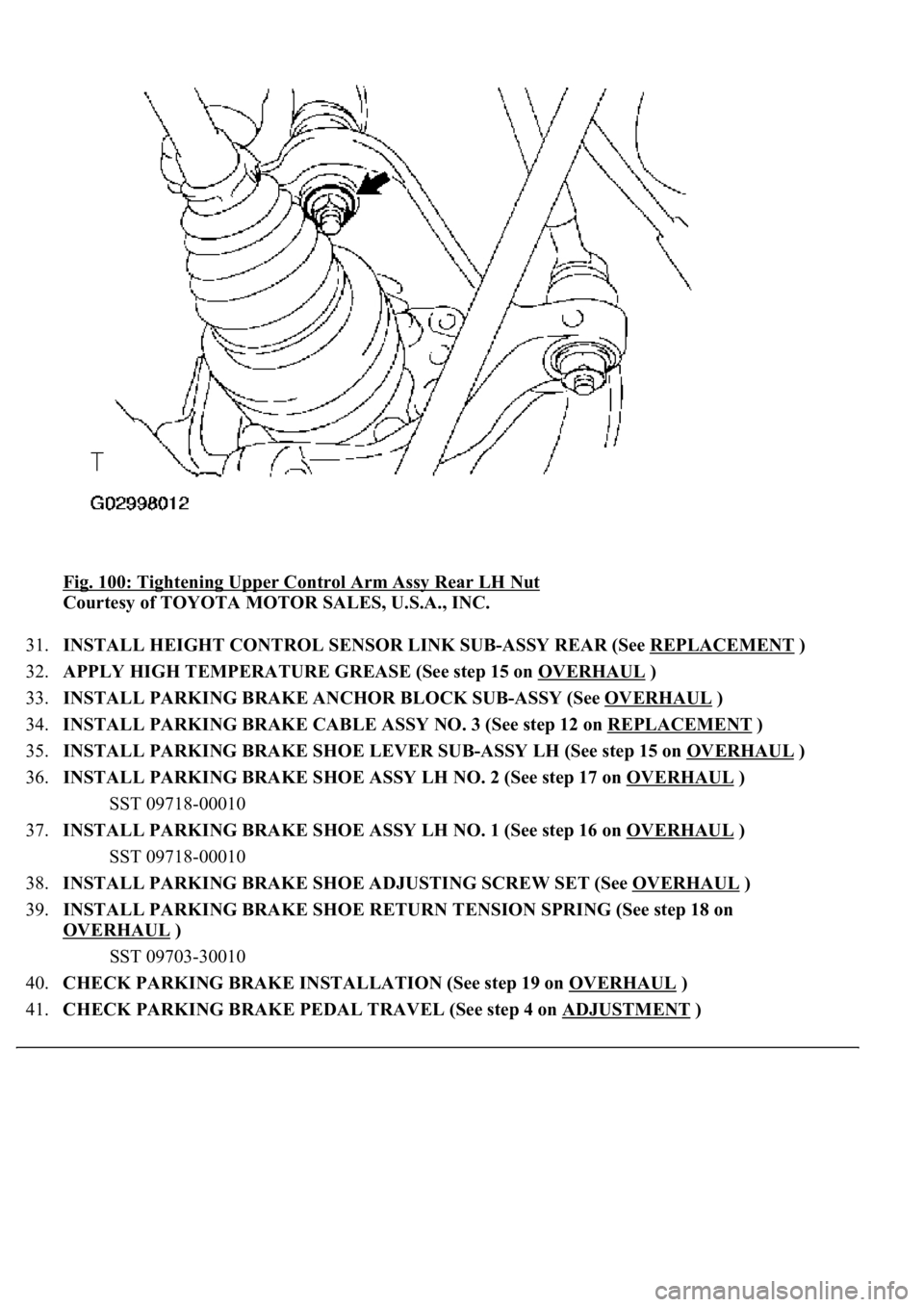
Fig. 100: Tightening Upper Control Arm Assy Rear LH Nut
Courtesy of TOYOTA MOTOR SALES, U.S.A., INC.
31.INSTALL HEIGHT CONTROL SENSOR LINK SUB-ASSY REAR (See REPLACEMENT
)
32.APPLY HIGH TEMPERATURE GREASE (See step 15 on OVERHAUL
)
33.INSTALL PARKING BRAKE ANCHOR BLOCK SUB-ASSY (See OVERHAUL
)
34.INSTALL PARKING BRAKE CABLE ASSY NO. 3 (See step 12 on REPLACEMENT
)
35.INSTALL PARKING BRAKE SHOE LEVER SUB-ASSY LH (See step 15 on OVERHAUL
)
36.INSTALL PARKING BRAKE SHOE ASSY LH NO. 2 (See step 17 on OVERHAUL
)
SST 09718-00010
37.INSTALL PARKING BRAKE SHOE ASSY LH NO. 1 (See step 16 on OVERHAUL
)
SST 09718-00010
38.INSTALL PARKING BRAKE SHOE ADJUSTING SCREW SET (See OVERHAUL
)
39.INSTALL PARKING BRAKE SHOE RETURN TENSION SPRING (See step 18 on
OVERHAUL
)
SST 09703-30010
40.CHECK PARKING BRAKE INSTALLATION (See step 19 on OVERHAUL
)
41.CHECK PARKING BRAKE PEDAL TRAVEL (See step 4 on ADJUSTMENT
)
Page 2414 of 4500
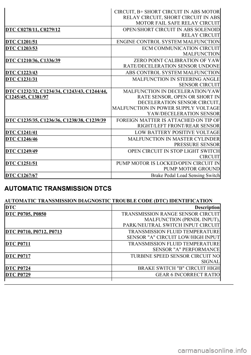
AUTOMATIC TRANSMISSION DIAGNOSTIC TROUBLE CODE (DTC) IDENTIFICATION
CIRCUIT, B+ SHORT CIRCUIT IN ABS MOTOR
RELAY CIRCUIT, SHORT CIRCUIT IN ABS
MOTOR FAIL SAFE RELAY CIRCUIT
DTC C0278/11, C0279/12 OPEN/SHORT CIRCUIT IN ABS SOLENOID
RELAY CIRCUIT
DTC C1201/51 ENGINE CONTROL SYSTEM MALFUNCTION
DTC C1203/53 ECM COMMUNICATION CIRCUIT
MALFUNCTION
DTC C1210/36, C1336/39 ZERO POINT CALIBRATION OF YAW
RATE/DECELERATION SENSOR UNDONE
DTC C1223/43 ABS CONTROL SYSTEM MALFUNCTION
DTC C1231/31 MALFUNCTION IN STEERING ANGLE
SENSOR CIRCUIT
DTC C1232/32, C1234/34, C1243/43, C1244/44,
C1245/45, C1381/97
MALFUNCTION IN DECELERATION/YAW
RATE SENSOR, OPEN OR SHORT IN
DECELERATION SENSOR CIRCUIT,
MALFUNCTION IN POWER SUPPLY VOLTAGE
YAW/DECELERATION SENSOR
DTC C1235/35, C1236/36, C1238/38, C1239/39 FOREIGN MATTER IS ATTACHED ON TIP OF
RIGHT/LEFT FRONT/REAR SENSOR
DTC C1241/41 LOW BATTERY POSITIVE VOLTAGE
DTC C1246/46 MALFUNCTION IN MASTER CYLINDER
PRESSURE SENSOR
DTC C1249/49 OPEN CIRCUIT IN STOP LIGHT SWITCH
CIRCUIT
DTC C1251/51 PUMP MOTOR IS LOCKED/OPEN CIRCUIT IN
PUMP MOTOR GROUND
DTC C1267/67 Brake Pedal Load Sensing Switch
DTCDescription
DTC P0705, P0850 TRANSMISSION RANGE SENSOR CIRCUIT
MALFUNCTION (PRNDL INPUT),
PARK/NEUTRAL SWITCH INPUT CIRCUIT
DTC P0710, P0712, P0713 TRANSMISSION FLUID TEMPERATURE
SENSOR "A" CIRCUIT LOW/HIGH INPUT
DTC P0711 TRANSMISSION FLUID TEMPERATURE
SENSOR "A" PERFORMANCE
DTC P0717 TURBINE SPEED SENSOR CIRCUIT NO
SIGNAL
DTC P0724 BRAKE SWITCH "B" CIRCUIT HIGH
DTC P0729 GEAR 6 INCORRECT RATIO
Page 2421 of 4500
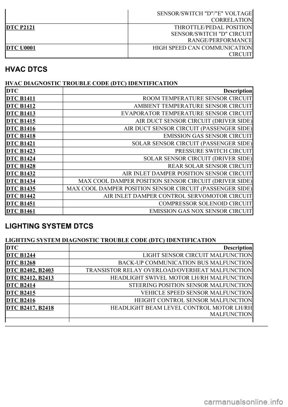
HVAC DIAGNOSTIC TROUBLE CODE (DTC) IDENTIFICATION
LIGHTING SYSTEM DIAGNOSTIC TROUBLE CODE (DTC) IDENTIFICATION
SENSOR/SWITCH "D"/"E" VOLTAGE
CORRELATION
DTC P2121 THROTTLE/PEDAL POSITION
SENSOR/SWITCH "D" CIRCUIT
RANGE/PERFORMANCE
DTC U0001 HIGH SPEED CAN COMMUNICATION
CIRCUIT
DTCDescription
DTC B1411 ROOM TEMPERATURE SENSOR CIRCUIT
DTC B1412 AMBIENT TEMPERATURE SENSOR CIRCUIT
DTC B1413 EVAPORATOR TEMPERATURE SENSOR CIRCUIT
DTC B1415 AIR DUCT SENSOR CIRCUIT (DRIVER SIDE)
DTC B1416 AIR DUCT SENSOR CIRCUIT (PASSENGER SIDE)
DTC B1418 EMISSION GAS SENSOR CIRCUIT
DTC B1421 SOLAR SENSOR CIRCUIT (PASSENGER SIDE)
DTC B1423 PRESSURE SWITCH CIRCUIT
DTC B1424 SOLAR SENSOR CIRCUIT (DRIVER SIDE)
DTC B1428 REAR SOLAR SENSOR CIRCUIT
DTC B1432 AIR INLET DAMPER POSITION SENSOR CIRCUIT
DTC B1434 MAX COOL DAMPER POSITION SENSOR CIRCUIT (DRIVER SIDE)
DTC B1435 MAX COOL DAMPER POSITION SENSOR CIRCUIT (PASSENGER SIDE)
DTC B1442 AIR INLET DAMPER CONTROL SERVOMOTOR CIRCUIT
DTC B1451 COMPRESSOR SOLENOID CIRCUIT
DTC B1461 EMISSION GAS NOX SENSOR CIRCUIT
DTCDescription
DTC B1244 LIGHT SENSOR CIRCUIT MALFUNCTION
DTC B1268 BACK-UP COMMUNICATION BUS MALFUNCTION
DTC B2402, B2403 TRANSISTOR RELAY OVERLOAD/OVERHEAT MALFUNCTION
DTC B2412, B2413 HEADLIGHT SWIVEL MOTOR LH/RH MALFUNCTION
DTC B2414 STEERING POSITION SENSOR MALFUNCTION
DTC B2415 VEHICLE SPEED SENSOR MALFUNCTION
DTC B2416 HEIGHT CONTROL SENSOR MALFUNCTION
DTC B2417, B2418 HEADLIGHT BEAM LEVEL CONTROL MOTOR LH/RH
MALFUNCTION
Page 2631 of 4500
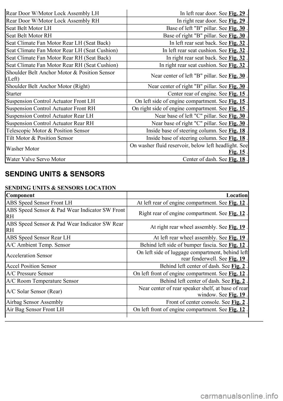
SENDING UNITS & SENSORS LOCATION
Rear Door W/Motor Lock Assembly LHIn left rear door. See Fig. 29 .
Rear Door W/Motor Lock Assembly RHIn right rear door. See Fig. 29 .
Seat Belt Motor LHBase of left "B" pillar. See Fig. 30 .
Seat Belt Motor RHBase of right "B" pillar. See Fig. 30 .
Seat Climate Fan Motor Rear LH (Seat Back)In left rear seat back. See Fig. 32 .
Seat Climate Fan Motor Rear LH (Seat Cushion)In left rear seat cushion. See Fig. 32 .
Seat Climate Fan Motor Rear RH (Seat Back)In right rear seat back. See Fig. 32 .
Seat Climate Fan Motor Rear RH (Seat Cushion)In right rear seat cushion. See Fig. 32 .
Shoulder Belt Anchor Motor & Position Sensor
(Left)Near center of left "B" pillar. See Fig. 30 .
Shoulder Belt Anchor Motor (Right)Near center of right "B" pillar. See Fig. 30 .
StarterCenter rear of engine. See Fig. 15 .
Suspension Control Actuator Front LHOn left side of engine compartment. See Fig. 15 .
Suspension Control Actuator Front RHOn right side of engine compartment. See Fig. 15 .
Suspension Control Actuator Rear LHNear base of left "C" pillar. See Fig. 30 .
Suspension Control Actuator Rear RHNear base of right "C" pillar. See Fig. 30 .
Telescopic Motor & Position SensorInside base of steering column. See Fig. 18 .
Tilt Motor & Position SensorInside base of steering column. See Fig. 18 .
Washer MotorOn washer fluid reservoir, below left headlight. See
Fig. 15
.
Water Valve Servo MotorCenter of dash. See Fig. 18 .
ComponentLocation
ABS Speed Sensor Front LHAt left rear of engine compartment. See Fig. 12 .
ABS Speed Sensor & Pad Wear Indicator SW Front
RHRight rear of engine compartment. See Fig. 12 .
ABS Speed Sensor & Pad Wear Indicator SW Rear
RHAt right rear wheel assembly. See Fig. 19 .
ABS Speed Sensor Rear LHAt left rear wheel assembly. See Fig. 19 .
A/C Ambient Temp. SensorBehind left side of bumper fascia. See Fig. 12 .
Acceleration SensorOn left side of luggage compartment, behind left
rear fenderwell. See Fig. 19
.
Accel Position SensorBehind left center of dash. See Fig. 2 .
A/C Pressure SensorOn left front of engine compartment. See Fig. 12 .
A/C Room Temperature SensorBehind left center of dash. See Fig. 2 .
A/C Solar Sensor (Rear)Near center of rear speaker shelf, at base of rear
window. See Fig. 19
.
Airbag Sensor AssemblyFront of center console. See Fig. 2 .
Air Bag Sensor Front LHOn left front of engine compartment. See Fig. 12 .
Page 2669 of 4500
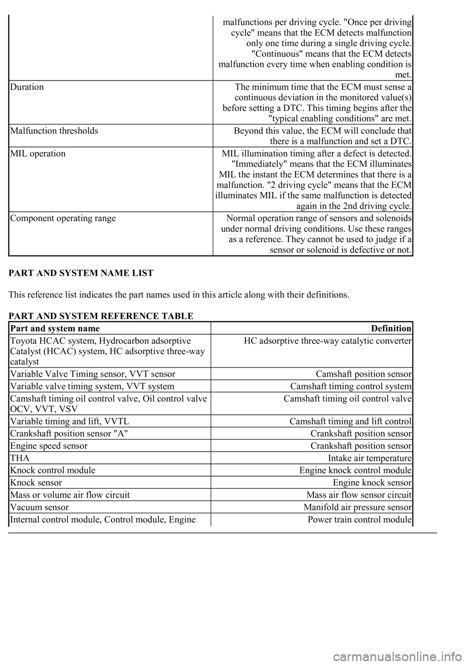
PART AND SYSTEM NAME LIST
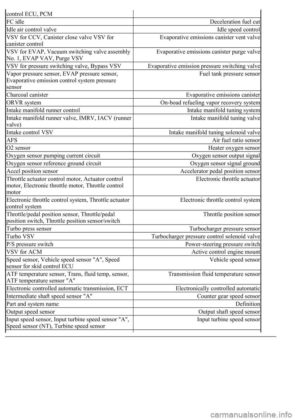
This reference list indicates the part names used in this article along with their definitions.
PART AND SYSTEM REFERENCE TABLE
malfunctions per driving cycle. "Once per driving
cycle" means that the ECM detects malfunction
only one time during a single driving cycle.
"Continuous" means that the ECM detects
malfunction every time when enabling condition is
met.
DurationThe minimum time that the ECM must sense a
continuous deviation in the monitored value(s)
before setting a DTC. This timing begins after the
"typical enabling conditions" are met.
Malfunction thresholdsBeyond this value, the ECM will conclude that
there is a malfunction and set a DTC.
MIL operationMIL illumination timing after a defect is detected.
"Immediately" means that the ECM illuminates
MIL the instant the ECM determines that there is a
malfunction. "2 driving cycle" means that the ECM
illuminates MIL if the same malfunction is detected
again in the 2nd driving cycle.
Component operating rangeNormal operation range of sensors and solenoids
under normal driving conditions. Use these ranges
as a reference. They cannot be used to judge if a
sensor or solenoid is defective or not.
Part and system nameDefinition
Toyota HCAC system, Hydrocarbon adsorptive
Catalyst (HCAC) system, HC adsorptive three-way
catalystHC adsorptive three-way catalytic converter
Variable Valve Timing sensor, VVT sensorCamshaft position sensor
Variable valve timing system, VVT systemCamshaft timing control system
Camshaft timing oil control valve, Oil control valve
OCV, VVT, VSVCamshaft timing oil control valve
Variable timing and lift, VVTLCamshaft timing and lift control
Crankshaft position sensor "A"Crankshaft position sensor
Engine speed sensorCrankshaft position sensor
THAIntake air temperature
Knock control moduleEngine knock control module
Knock sensorEngine knock sensor
Mass or volume air flow circuitMass air flow sensor circuit
Vacuum sensorManifold air pressure sensor
Internal control module, Control module, Engine Power train control module
Page 2670 of 4500
control ECU, PCM
FC idleDeceleration fuel cut
Idle air control valveIdle speed control
VSV for CCV, Canister close valve VSV for
canister controlEvaporative emissions canister vent valve
VSV for EVAP, Vacuum switching valve assembly
No. 1, EVAP VAV, Purge VSVEvaporative emissions canister purge valve
VSV for pressure switching valve, Bypass VSVEvaporative emission pressure switching valve
Vapor pressure sensor, EVAP pressure sensor,
Evaporative emission control system pressure
sensorFuel tank pressure sensor
Charcoal canisterEvaporative emissions canister
ORVR systemOn-boad refueling vapor recovery system
Intake manifold runner controlIntake manifold tuning system
Intake manifold runner valve, IMRV, IACV (runner
valve)Intake manifold tuning valve
Intake control VSVIntake manifold tuning solenoid valve
AFSAir fuel ratio sensor
O2 sensorHeater oxygen sensor
Oxygen sensor pumping current circuitOxygen sensor output signal
Oxygen sensor reference ground circuitOxygen sensor signal ground
Accel position sensorAccelerator pedal position sensor
Throttle actuator control motor, Actuator control
motor, Electronic throttle motor, Throttle control
motorElectronic throttle actuator
Electronic throttle control system, Throttle actuator
control systemElectronic throttle control system
Throttle/pedal position sensor, Throttle/pedal
position switch, Throttle position sensor/switchThrottle position sensor
Turbo press sensorTurbocharger pressure sensor
Turbo VSVTurbocharger pressure control solenoid valve
P/S pressure switchPower-steering pressure switch
VSV for ACMActive control engine mount
Speed sensor, Vehicle speed sensor "A", Speed
sensor for skid control ECUVehicle speed sensor
ATF temperature sensor, Trans, fluid temp, sensor,
ATF temperature sensor "A"Transmission fluid temperature sensor
Electronic controlled automatic transmission, ECTElectronically controlled automatic
Intermediate shaft speed sensor "A"Counter gear speed sensor
Part and system nameDefinition
Output speed sensorOutput shaft speed sensor
<002c00510053005800570003005600530048004800470003005600480051005600520055000f0003002c005100530058005700030057005800550045004c005100480003005600530048004800470003005600480051005600520055000300050024000500
0f0003[
Speed sensor (NT), Turbine speed sensorInput turbine speed sensor
Page 2725 of 4500
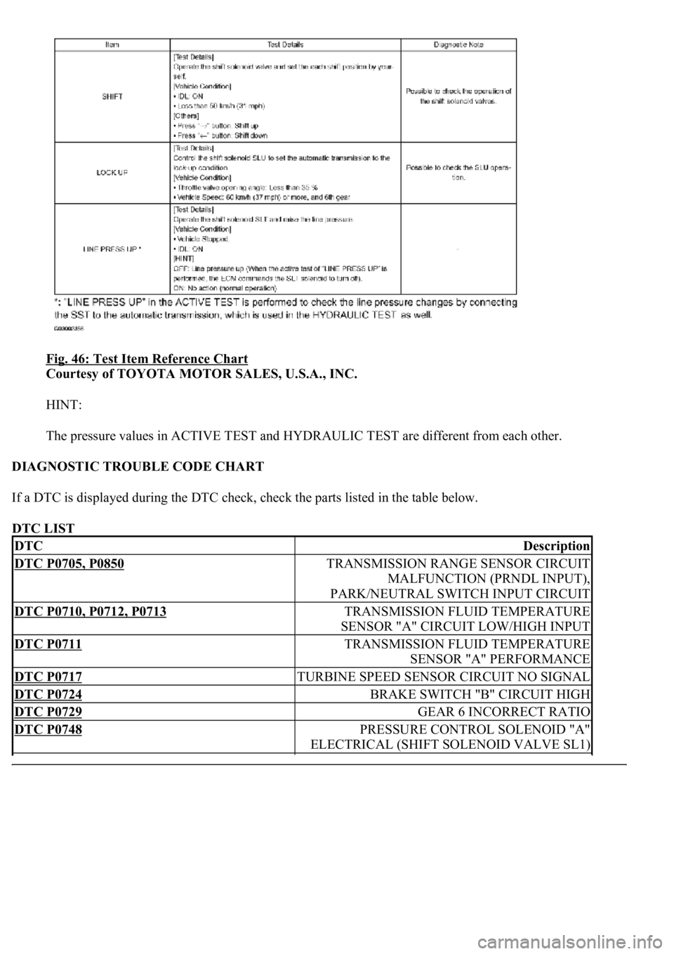
Fig. 46: Test Item Reference Chart
Courtesy of TOYOTA MOTOR SALES, U.S.A., INC.
HINT:
The pressure values in ACTIVE TEST and HYDRAULIC TEST are different from each other.
DIAGNOSTIC TROUBLE CODE CHART
If a DTC is displayed during the DTC check, check the parts listed in the table below.
DTC LIST
DTCDescription
DTC P0705, P0850TRANSMISSION RANGE SENSOR CIRCUIT
MALFUNCTION (PRNDL INPUT),
PARK/NEUTRAL SWITCH INPUT CIRCUIT
DTC P0710, P0712, P0713TRANSMISSION FLUID TEMPERATURE
SENSOR "A" CIRCUIT LOW/HIGH INPUT
DTC P0711TRANSMISSION FLUID TEMPERATURE
SENSOR "A" PERFORMANCE
DTC P0717TURBINE SPEED SENSOR CIRCUIT NO SIGNAL
DTC P0724BRAKE SWITCH "B" CIRCUIT HIGH
DTC P0729GEAR 6 INCORRECT RATIO
DTC P0748PRESSURE CONTROL SOLENOID "A"
ELECTRICAL (SHIFT SOLENOID VALVE SL1)
Page 2740 of 4500
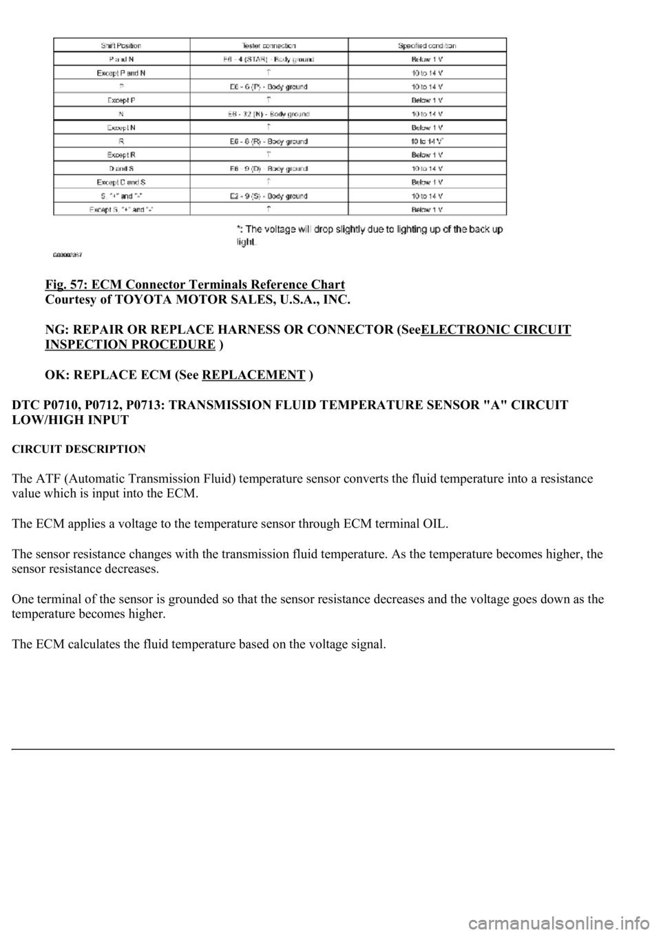
Fig. 57: ECM Connector Terminals Reference Chart
Courtesy of TOYOTA MOTOR SALES, U.S.A., INC.
NG: REPAIR OR REPLACE HARNESS OR CONNECTOR (SeeELECTRONIC CIRCUIT
INSPECTION PROCEDURE )
OK: REPLACE ECM (See REPLACEMENT
)
DTC P0710, P0712, P0713: TRANSMISSION FLUID TEMPERATURE SENSOR "A" CIRCUIT
LOW/HIGH INPUT
CIRCUIT DESCRIPTION
The ATF (Automatic Transmission Fluid) temperature sensor converts the fluid temperature into a resistance
value which is input into the ECM.
The ECM applies a voltage to the temperature sensor through ECM terminal OIL.
The sensor resistance changes with the transmission fluid temperature. As the temperature becomes higher, the
sensor resistance decreases.
One terminal of the sensor is grounded so that the sensor resistance decreases and the voltage goes down as the
temperature becomes higher.
The ECM calculates the fluid temperature based on the volta
ge signal.