Page 1598 of 4500

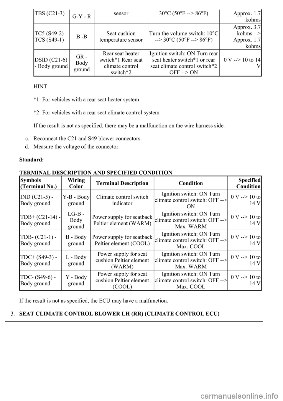
HINT:
*1: For vehicles with a rear seat heater system
*2: For vehicles with a rear seat climate control system
If the result is not as specified, there may be a malfunction on the wire harness side.
c. Reconnect the C21 and S49 blower connectors.
d. Measure the voltage of the connector.
Standard:
TERMINAL DESCRIPTION AND SPECIFIED CONDITION
If the result is not as specified, the ECU may have a malfunction.
3.SEAT CLIMATE CONTROL BLOWER LH (RR) (CLIMATE CONTROL ECU)
TBS (C21-3)G-Y - Rsensor30°C (50°F --> 86°F)Approx. 1.7
kohms
TC5 (S49-2) -
TCS (S49-1)B -BSeat cushion
temperature sensorTurn the volume switch: 10°C
--> 30°C (50°F --> 86°F)
Approx. 3.7
kohms -->
Approx. 1.7
kohms
DSID (C21-6)
- Body groundGR -
Body
groundRear seat heater
switch*1 Rear seat
climate control
switch*2Ignition switch: ON Turn rear
seat heater switch*1 or rear
seat climate control switch*2
OFF --> ON
0 V --> 10 to 14
V
Symbols
(Terminal No.)Wiring
ColorTerminal DescriptionConditionSpecified
Condition
IND (C21-5) -
Body groundY-B - Body
groundClimate control switch
indicatorIgnition switch: ON Turn
climate control switch: OFF -->
ON0 V --> 10 to
14 V
TDB+ (C21-14) -
Body groundLG-B -
Body
groundPower supply for seatback
Peltier element (WARM)Ignition switch: ON Turn
climate control switch: OFF -->
Max. WARM0 V --> 10 to
14 V
TDB- (C21-1) -
Body groundB - Body
groundPower supply for seatback
Peltier element (COOL)Ignition switch: ON Turn
climate control switch: OFF -->
Max. COOL0 V --> 10 to
14 V
TDC+ (S49-3) -
Body groundL - Body
groundPower supply for seat
cushion Peltier element
(WARM)Ignition switch: ON Turn
climate control switch: OFF -->
Max. WARM0 V --> 10 to
14 V
TDC- (S49-6) -
Body groundY - Body
groundPower supply for seat
cushion Peltier element
(COOL)Ignition switch: ON Turn
climate control switch: OFF -->
Max. COOL0 V --> 10 to
14 V
Page 1599 of 4500

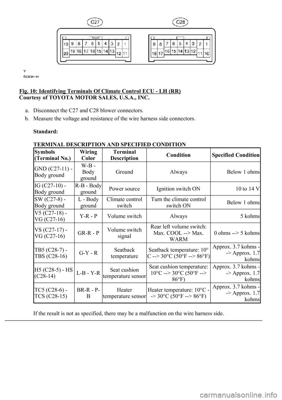
Fig. 10: Identifying Terminals Of Climate Control ECU - LH (RR)
Courtesy of TOYOTA MOTOR SALES, U.S.A., INC.
a. Disconnect the C27 and C28 blower connectors.
b. Measure the voltage and resistance of the wire harness side connectors.
Standard:
TERMINAL DESCRIPTION AND SPECIFIED CONDITION
If the result is not as specified, there ma
y be a malfunction on the wire harness side.
Symbols
(Terminal No.)Wiring
ColorTerminal
DescriptionConditionSpecified Condition
GND (C27-11) -
Body groundW-B -
Body
ground
GroundAlwaysBelow 1 ohms
IG (C27-10) -
Body groundR-B - Body
groundPower sourceIgnition switch ON10 to 14 V
SW (C27-8) -
Body groundL - Body
groundClimate control
switchTurn the climate control
switch ONBelow 1 ohms
V5 (C27-18) -
VG (C27-16)Y-R - PVolume switchAlways5 kohms
VS (C27-17) -
VG (C27-16)GR-R - PVolume switch
signalRear left volume switch:
Max. COOL --> Max.
WARM
0 ohms --> 5 kohms
TB5 (C28-7) -
TBS (C28-16)G-Y - RSeatback
temperatureSeatback temperature: 10°
C --> 30°C (50°F --> 86°F)Approx. 3.7 kohms -
-> Approx. 1.7
kohms
H5 (C28-5) - HS
(C28-14)L-B - Y-RSeat cushion
temperature sensorSeat cushion temperature:
10°C --> 30°C (50°F -->
86°F)Approx. 3.7 kohms -
-> Approx. 1.7
kohms
TC5 (C28-6) -
TCS (C28-15)BR-R - P-
BHeater
temperature sensorHeater temperature: 10°C -
-> 30°C (50°F --> 86°F)Approx. 3.7 kohms -
-> Approx. 1.7
kohms
Page 1602 of 4500

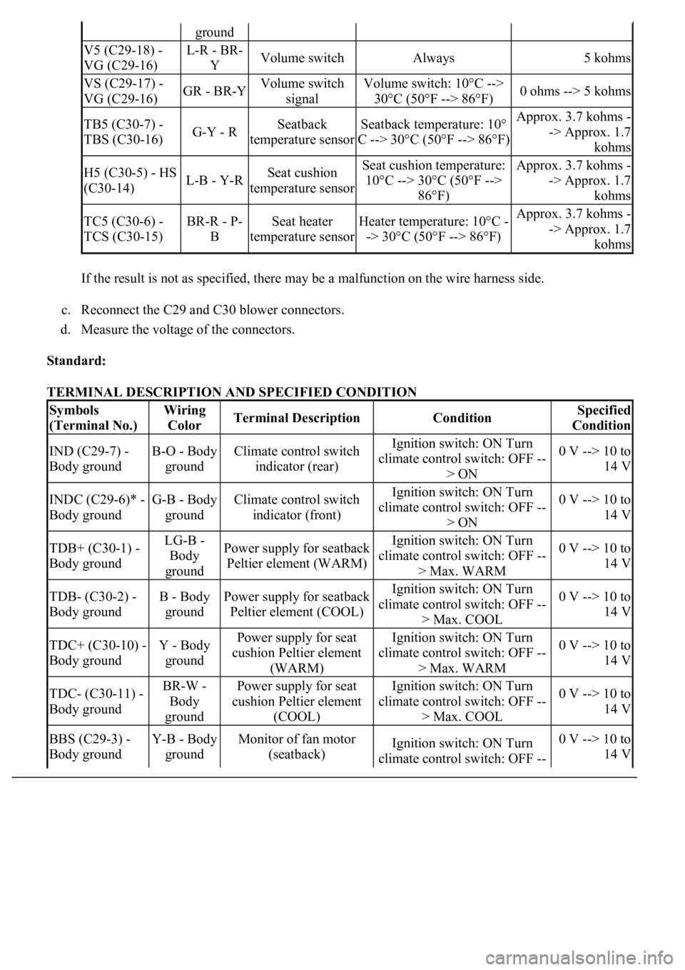
If the result is not as specified, there may be a malfunction on the wire harness side.
c. Reconnect the C29 and C30 blower connectors.
d. Measure the voltage of the connectors.
Standard:
TERMINAL DESCRIPTION AND SPECIFIED CONDITION
ground
V5 (C29-18) -
VG (C29-16)L-R - BR-
YVolume switchAlways5 kohms
VS (C29-17) -
VG (C29-16)GR - BR-YVolume switch
signalVolume switch: 10°C -->
30°C (50°F --> 86°F)0 ohms --> 5 kohms
TB5 (C30-7) -
TBS (C30-16)G-Y - RSeatback
temperature sensorSeatback temperature: 10°
C --> 30°C (50°F --> 86°F)Approx. 3.7 kohms -
-> Approx. 1.7
kohms
H5 (C30-5) - HS
(C30-14)L-B - Y-RSeat cushion
temperature sensorSeat cushion temperature:
10°C --> 30°C (50°F -->
86°F)Approx. 3.7 kohms -
-> Approx. 1.7
kohms
TC5 (C30-6) -
TCS (C30-15)BR-R - P-
BSeat heater
temperature sensorHeater temperature: 10°C -
-> 30°C (50°F --> 86°F)Approx. 3.7 kohms -
-> Approx. 1.7
kohms
Symbols
(Terminal No.)Wiring
ColorTerminal DescriptionConditionSpecified
Condition
IND (C29-7) -
Body groundB-O - Body
groundClimate control switch
indicator (rear)Ignition switch: ON Turn
climate control switch: OFF --
> ON0 V --> 10 to
14 V
INDC (C29-6)* -
Body groundG-B - Body
groundClimate control switch
indicator (front)Ignition switch: ON Turn
climate control switch: OFF --
> ON0 V --> 10 to
14 V
TDB+ (C30-1) -
Body groundLG-B -
Body
groundPower supply for seatback
Peltier element (WARM)Ignition switch: ON Turn
climate control switch: OFF --
> Max. WARM0 V --> 10 to
14 V
TDB- (C30-2) -
Body groundB - Body
groundPower supply for seatback
Peltier element (COOL)Ignition switch: ON Turn
climate control switch: OFF --
> Max. COOL0 V --> 10 to
14 V
TDC+ (C30-10) -
Body groundY - Body
groundPower supply for seat
cushion Peltier element
(WARM)Ignition switch: ON Turn
climate control switch: OFF --
> Max. WARM0 V --> 10 to
14 V
TDC- (C30-11) -
Body groundBR-W -
Body
groundPower supply for seat
cushion Peltier element
(COOL)Ignition switch: ON Turn
climate control switch: OFF --
> Max. COOL0 V --> 10 to
14 V
BBS (C29-3) -
Body groundY-B - Body
groundMonitor of fan motor
(seatback)Ignition switch: ON Turn
climate control switch: OFF --0 V --> 10 to
14 V
Page 1743 of 4500
Fig. 10: Communication Signal Reference Chart BEAN (Column)
Courtesy of TOYOTA MOTOR SALES, U.S.A., INC.
AVC-LAN:
Fig. 11: Communication Signal Reference Chart (AVC
-LAN)
Courtesy of TOYOTA MOTOR SALES, U.S.A., INC.
1.METER GAUGE AND WARNING/INDICATOR
GAUGE:
GAUGE DETAIL
WARNING/INDICATOR:
ItemDetail
SpeedometerBased on a signal received from the wheel speed sensor, the skid control ECU
calculates vehicle speed and transmits the data to the meter (Direct line).
TachometerECM transmits engine speed to the meter display (Direct line).
Water Temperature
GaugeDisplays water temperature receiving a signal from the ECM (BEAN).
Fuel GaugeReceives the fuel sender gauge signal from the luggage room J/B ECU (BEAN).
Page 1779 of 4500

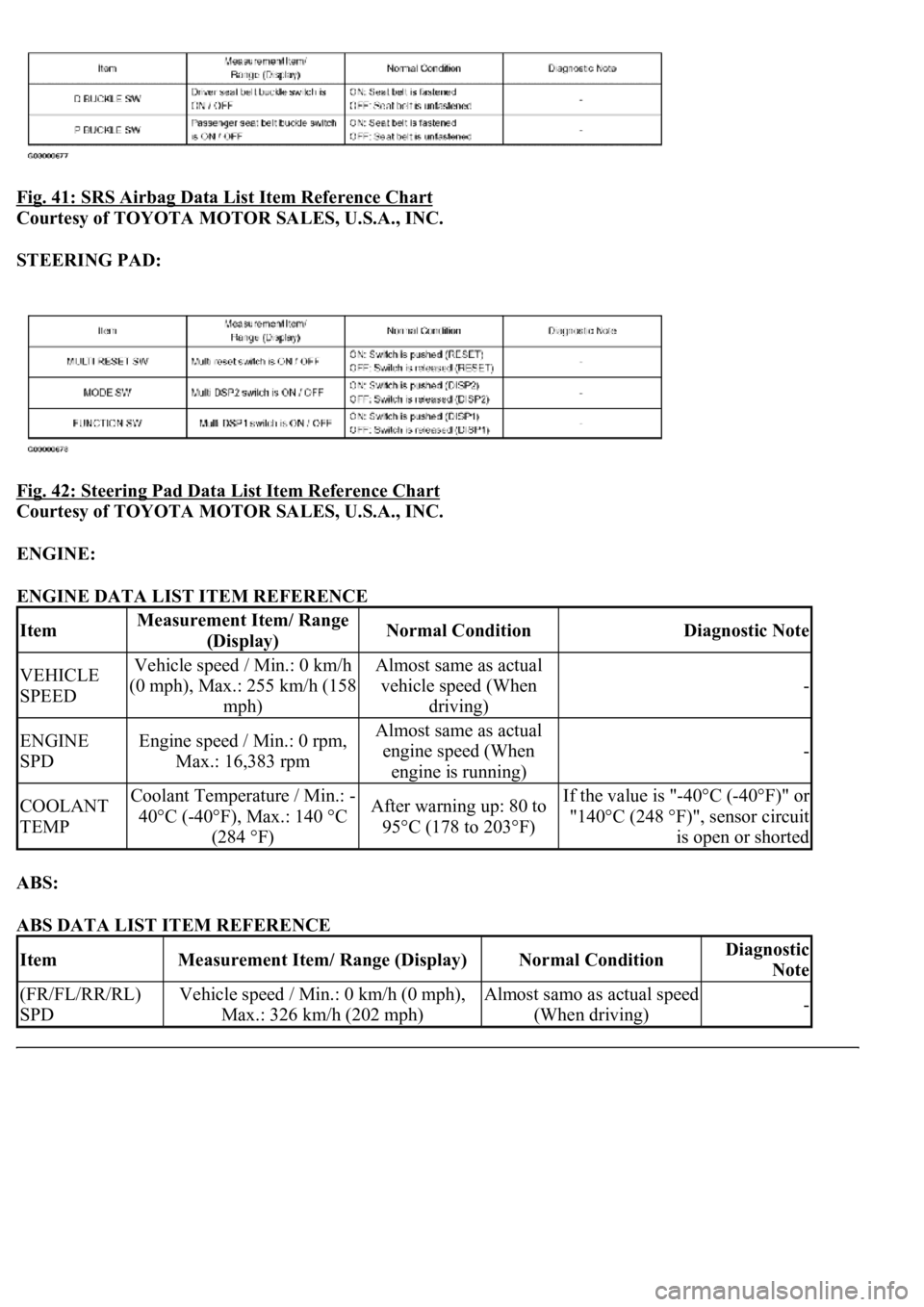
Fig. 41: SRS Airbag Data List Item Reference Chart
Courtesy of TOYOTA MOTOR SALES, U.S.A., INC.
STEERING PAD:
Fig. 42: Steering Pad Data List Item Reference Chart
Courtesy of TOYOTA MOTOR SALES, U.S.A., INC.
ENGINE:
ENGINE DATA LIST ITEM REFERENCE
ABS:
ABS DATA LIST ITEM REFERENCE
ItemMeasurement Item/ Range
(Display)Normal ConditionDiagnostic Note
VEHICLE
SPEEDVehicle speed / Min.: 0 km/h
(0 mph), Max.: 255 km/h (158
mph)Almost same as actual
vehicle speed (When
driving)
-
ENGINE
SPDEngine speed / Min.: 0 rpm,
Max.: 16,383 rpmAlmost same as actual
engine speed (When
engine is running)
-
COOLANT
TEMPCoolant Temperature / Min.: -
40°C (-40°F), Max.: 140 °C
(284 °F)After warning up: 80 to
95°C (178 to 203°F)If the value is "-40°C (-40°F)" or
"140°C (248 °F)", sensor circuit
is open or shorted
ItemMeasurement Item/ Range (Display)Normal ConditionDiagnostic
Note
(FR/FL/RR/RL)
SPDVehicle speed / Min.: 0 km/h (0 mph),
Max.: 326 km/h (202 mph)Almost samo as actual speed
(When driving)-
Page 1810 of 4500
Fig. 63: Identifying Fuel Sender Gauge Assy And Luggage Room Junction Block Assy Connector
Terminals
Courtesy of TOYOTA MOTOR SALES, U.S.A., INC.
NG: REPAIR OR REPLACE HARNESS OR CONNECTOR
OK: REPLACE LUGGAGE ROOM JUNCTION BLOCK ASSY
WIRING DIAGRAM
Fig. 64: Water Temperature Receiver Gauge Wiring Diagram
Courtesy of TOYOTA MOTOR SALES, U.S.A., INC.
INSPECTION PROCEDURE
HINT:
If there is an open or short in the engine coolant temperature sensor circuit, the ECM outputs DTCs. Perform
troubleshooting with the "SFI System 10-2".
1.PERFORM ACTIVE TEST BY HAND-HELD TESTER
a. Operate the hand-held tester according to the steps on the display and select the "ACTIVE TEST".
METER:
ACTIVE TEST REFERENCE
Page 1811 of 4500
OK:
Needle indication is normal.
NG: REPLACE COMBINATION METER ASSY (SEE OVERHAUL
)
OK: GO TO NEXT STEP
2.READ VALUE OF HAND-HELD TESTER (ENGINE COOLANT)
a. Operate the hand-held tester according to the steps on the display and select the "DATA LIST".
ENGINE:
DATA LIST REFERENCE
OK:
Coolant temperature displayed on the tester is between 80°C (176°F) and 95°C (203°F) after
warning up.
NG: GO TO ENGINE CONTROL SYSTEM (SEE REPLACEMENT
)
OK: GO TO NEXT STEP
3.REPLACE COMBINATION METER ASSY
OK:
Normal operation
NG: GO TO ENGINE CONTROL SYSTEM (SEE REPLACEMENT
)
OK: END
WIRING DIAGRAM
ItemTest DetailsDiagnostic Note
COOLANT TEMPLOW /NORMAL /HI-
ItemMeasurement Item/ Range
(Display)Normal ConditionDiagnostic Note
COOLANT
TEMPCoolant Temperature / Min.: -
40°C (-40°F), Max.: 140°C
(284 °F)After warming up: 80
to 95°C (176 to 203°
F)If the value is "-40°C (-40°F)" or
"140°C (284°F)", sensor circuit is
open or shorted.
Page 1858 of 4500
ON-VEHICLE INSPECTION
1.CHECK COOLING FAN SYSTEM
a. Look at the chart below. Check that when the cooling fan is in the condition on the left, its
operation is what is written on the right.
Standard when engine coolant temperature is below 82°C (180°F):
CONDITION AND OPERATION SPECIFICATION
If the fan does not operate as specified, proceed to next step.
2.INSPECT COOLING FAN MOTOR
a. Remove the air cleaner inlet No. 1.
b. Disconnect the 2 connectors.
c. Connect the battery and ammeter.
d. Check that the fan rotates smoothly, and then check the amperage on the ammeter.
Standard: 9.2 to 11.0 A at 20° C (68° F)
If the result is not as specified, replace the fan motor.
If the fan operates, proceed to the next step.
ConditionOperation (Fan Speed)
Ignition ON at engine stoppingNot rotating
A/C switch OFF at idle speedNot rotating
A/C switch ON at idle speedRotating (Low speed)
Disconnect ECT sensor connector at idle speedRotating (High speed)