Page 4160 of 4500
59.INSPECT FUEL PUMP OPERATION AND CHECK FOR FUEL LEAKS (See ON-VEHICLE
INSPECTION )
60.CHECK FOR EXHAUST GAS LEAKS (See REPLACEMENT
)
Page 4196 of 4500
overheating etc.
9.DO NOT OPERATE ENGINE AND COMPRESSOR WITH NO REFRIGERANT
10.SUPPLEMENTAL RESTRAINT SYSTEM (SRS)
The LEXUS LS430 is equipped with an SRS (Supplemental Restraint system) such as the driver, front
passenger, side, curtain shield air bags etc.. Failure to carry out service operation in the correct sequence
could cause the SRS to unexpectedly deploy during servicing, possibly leading to a serious accident.
Before servicing (including removal or installation of parts, inspection or replacement), be sure to read
the precautionary notices in PRECAUTION
.
11.PRECAUTION FOR DISCONNECTING THE BATTERY CABLE
DISCONNECTING BATTERY CABLE
LOCATION
System NameProceed To
Front Power Seat Control SystemINITIALIZATION
Page 4197 of 4500
Fig. 4: Identifying Air Conditioning System Components And Replacements Location (1 Of 2)
Courtesy of TOYOTA MOTOR SALES, U.S.A., INC.
Page 4198 of 4500
Fig. 5: Identifying Air Conditioning System Components And Replacements Location (2 Of 2)
Courtesy of TOYOTA MOTOR SALES, U.S.A., INC.
Page 4209 of 4500

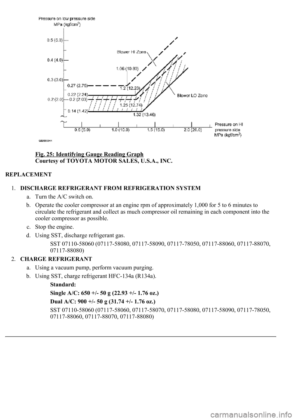
Fig. 25: Identifying Gauge Reading Graph
Courtesy of TOYOTA MOTOR SALES, U.S.A., INC.
REPLACEMENT
1.DISCHARGE REFRIGERANT FROM REFRIGERATION SYSTEM
a. Turn the A/C switch on.
b. Operate the cooler compressor at an engine rpm of approximately 1,000 for 5 to 6 minutes to
circulate the refrigerant and collect as much compressor oil remaining in each component into the
cooler compressor as possible.
c. Stop the engine.
d. Using SST, discharge refrigerant gas.
<00360036003700030013001a00140014001300100018001b0013001900130003000b0013001a00140014001a00100018001b0013001b0013000f00030013001a00140014001a00100018001b0013001c0013000f00030013001a00140014001a0010001a00
1b001300180013000f00030013001a00140014001a0010001b[8060, 07117-88070,
07117-88080)
2.CHARGE REFRIGERANT
a. Using a vacuum pump, perform vacuum purging.
b. Using SST, charge refrigerant HFC-134a (R134a).
Standard:
Single A/C: 650 +/- 50 g (22.93 +/- 1.76 oz.)
Dual A/C: 900 +/- 50 g (31.74 +/- 1.76 oz.)
<00360036003700030013001a00140014001300100018001b0013001900130003000b0013001a00140014001a00100018001b001300190013000f00030013001a00140014001a00100018001b0013001a0013000f00030013001a00140014001a0010001800
1b0013001b0013000f00030013001a00140014001a00100018[8090, 07117-78050,
07117-88060, 07117-88070, 07117-88080)
Page 4213 of 4500
Fig. 29: Identifying Refrigerant Line Components And Replacements (Single A/C)
Courtesy of TOYOTA MOTOR SALES, U.S.A., INC.
Page 4215 of 4500
Fig. 30: Identifying Refrigerant Line Components And Replacements (Dual A/C)
Courtesy of TOYOTA MOTOR SALES, U.S.A., INC.
COMPONENTS
Page 4216 of 4500
Fig. 31: Identifying Air Conditioning Panel Sub-Assy Components And Replacements
Courtesy of TOYOTA MOTOR SALES, U.S.A., INC.
REPLACEMENT
HINT:
Installation is in the reverse order of removal.
See COMPONENTS .
1.RESTORE SHIP MODE SETTING (W/ CD CHANGER) (See PRECAUTION
)
2.REMOVE INSTRUMENT PANEL FINISH PANEL LOWER CENTER (See step 26 in
REPLACEMENT
)
3.REMOVE PANEL INSTRUMENT CLUSTER FINISH LOWER (See step 27 in
REPLACEMENT
)
4.REMOVE RADIO RECEIVER ASSEMBLY W/BRACKET (See step 4 in REPLACEMENT
)
5.CONFIRM SHIP MODE (W/ CD CHANGER) (See PRECAUTION
)
6.REMOVE TEMPERATURE CONTROL SWITCH ASSY
a. Using a screwdriver, release the 2 claws and remove the temperature control switch.
HINT:
Tape the screwdriver tip before use.
b. Employ the same manner described above to the other side.
c. Disconnect the connectors.