Page 1512 of 4500
Fig. 7: Identifying Back Sonar Display
Courtesy of TOYOTA MOTOR SALES, U.S.A., INC.
h. Check the multi-information display, the multi-display and the buzzer sounding condition when the
clearance sonar sensor detects an obstacle.
Operation condition:
Front clearance sonar:
CLEARANCE SONAR MAIN SWITCH
Page 1515 of 4500
c. After turning the ignition switch to the ON position, wait for 2 seconds or more, then turn the
clearance sonar main switch on. Check the multi-information display and the buzzer sounding
condition.
Standard:
After the main switch is turned on, the multi-information display shows the Fig. 9
below
for approximatel
y 2 seconds and the buzzer sounds for approximately 1 second then the
detection mode begins.
Fig. 9: Identifying Multi
-Information Display
Courtesy of TOYOTA MOTOR SALES, U.S.A., INC.
HINT:
Multi-information display:
The malfunctioning sensor blinks on the display when the wire harness or the connector is
faulty and requires repair or replacement, or when trouble is detected in the ultrasonic sensor
circuits. After the sensor operation returns to normal, the detection mode will finish
normall
y.
Page 1516 of 4500
Fig. 10: Identifying Trouble Detection Display
Courtesy of TOYOTA MOTOR SALES, U.S.A., INC.
Multi-display:
The malfunctioning sensor is displayed when the wire harness or the connector is faulty and
requires repair or replacement, or when trouble is detected in the ultrasonic sensor circuits.
After the sensor operation returns to normal, the detection mode will finish normally.
Fig. 11: Identifying Trouble Detection Display (Multi
-Display)
Page 1517 of 4500

Courtesy of TOYOTA MOTOR SALES, U.S.A., INC.
HINT:
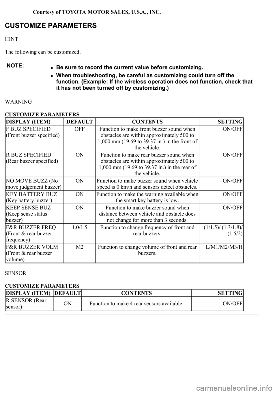
The following can be customized.
WARNING
CUSTOMIZE PARAMETERS
SENSOR
CUSTOMIZE PARAMETERS
DISPLAY (ITEM)DEFAULTCONTENTSSETTING
F BUZ SPECIFIED
(Front buzzer specified)OFFFunction to make front buzzer sound when
obstacles are within approximately 500 to
1,000 mm (19.69 to 39.37 in.) in the front of
the vehicle.ON/OFF
R BUZ SPECIFIED
(Rear buzzer specified)ONFunction to make rear buzzer sound when
obstacles are within approximately 500 to
1,000 mm (19.69 to 39.37 in.) in the rear of
the vehicle.ON/OFF
NO MOVE BUZZ (No
move judgement buzzer)ONFunction to make buzzer sound when vehicle
speed is 0 km/h and sensors detect obstacles.ON/OFF
KEY BATTERY BUZ
(Key battery buzzer)ONFunction to make the warning available when
the smart key battery is low.ON/OFF
KEEP SENSE BUZ
(Keep sense status
buzzer)ONFunction to make buzzer sound when
distance between vehicle and obstacle does
not change for more than 3 seconds.ON/OFF
F&R BUZZER FREQ
(Front & rear buzzer
frequency)1.0/1.5Function to change frequency of front and
rear buzzers.(1/1.5)/ (1.3/1.8)/
(1.5/2)
F&R BUZZER VOLM
(Front & rear buzzer
volume)M2Function to change volume of front and rear
buzzers.L/M1/M2/M3/H
DISPLAY (ITEM)DEFAULTCONTENTSSETTING
R SENSOR (Rear
sensor)ONFunction to make 4 rear sensors available.ON/OFF
Page 1518 of 4500

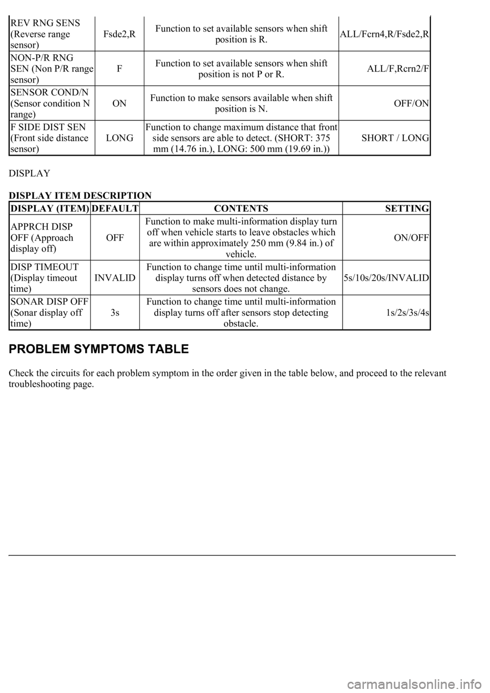
DISPLAY
DISPLAY ITEM DESCRIPTION
Check the circuits for each problem symptom in the order given in the table below, and proceed to the relevant
troubleshooting page.
REV RNG SENS
(Reverse range
sensor)
Fsde2,RFunction to set available sensors when shift
position is R.ALL/Fcrn4,R/Fsde2,R
NON-P/R RNG
SEN (Non P/R range
sensor)
FFunction to set available sensors when shift
position is not P or R.ALL/F,Rcrn2/F
SENSOR COND/N
(Sensor condition N
range)
ONFunction to make sensors available when shift
position is N.OFF/ON
F SIDE DIST SEN
(Front side distance
sensor)
LONG
Function to change maximum distance that front
side sensors are able to detect. (SHORT: 375
mm (14.76 in.), LONG: 500 mm (19.69 in.))
SHORT / LONG
DISPLAY (ITEM)DEFAULTCONTENTSSETTING
APPRCH DISP
OFF (Approach
display off)
OFF
Function to make multi-information display turn
off when vehicle starts to leave obstacles which
are within approximately 250 mm (9.84 in.) of
vehicle.
ON/OFF
DISP TIMEOUT
(Display timeout
time)
INVALID
Function to change time until multi-information
display turns off when detected distance by
sensors does not change.
5s/10s/20s/INVALID
SONAR DISP OFF
(Sonar display off
time)
3s
Function to change time until multi-information
display turns off after sensors stop detecting
obstacle.
1s/2s/3s/4s
Page 1521 of 4500

1.DESCRIPTION
a. DIAGNOSTIC SYSTEM
When troubleshooting a vehicle with the diagnosis system, the only difference from the usual
troubleshootin
g procedure is connecting the hand-held tester to the vehicle and reading
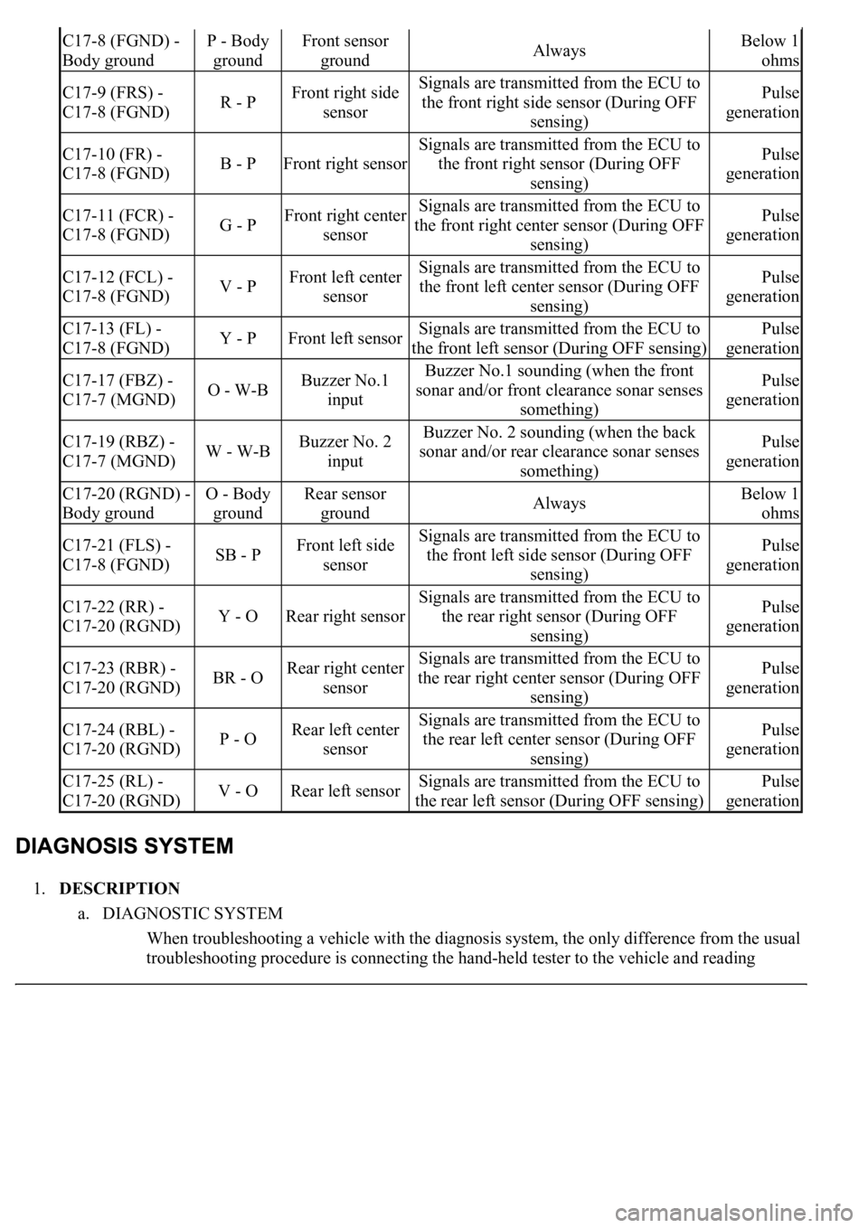
C17-8 (FGND) -
Body groundP - Body
groundFront sensor
groundAlwaysBelow 1
ohms
C17-9 (FRS) -
C17-8 (FGND)R - PFront right side
sensorSignals are transmitted from the ECU to
the front right side sensor (During OFF
sensing)Pulse
generation
C17-10 (FR) -
C17-8 (FGND)B - PFront right sensor
Signals are transmitted from the ECU to
the front right sensor (During OFF
sensing)Pulse
generation
C17-11 (FCR) -
C17-8 (FGND)G - PFront right center
sensorSignals are transmitted from the ECU to
the front right center sensor (During OFF
sensing)Pulse
generation
C17-12 (FCL) -
C17-8 (FGND)V - PFront left center
sensorSignals are transmitted from the ECU to
the front left center sensor (During OFF
sensing)Pulse
generation
C17-13 (FL) -
C17-8 (FGND)Y - PFront left sensorSignals are transmitted from the ECU to
the front left sensor (During OFF sensing)Pulse
generation
C17-17 (FBZ) -
C17-7 (MGND)O - W-BBuzzer No.1
inputBuzzer No.1 sounding (when the front
sonar and/or front clearance sonar senses
something)Pulse
generation
C17-19 (RBZ) -
C17-7 (MGND)W - W-BBuzzer No. 2
inputBuzzer No. 2 sounding (when the back
sonar and/or rear clearance sonar senses
something)Pulse
generation
C17-20 (RGND) -
Body groundO - Body
groundRear sensor
groundAlwaysBelow 1
ohms
C17-21 (FLS) -
C17-8 (FGND)SB - PFront left side
sensorSignals are transmitted from the ECU to
the front left side sensor (During OFF
sensing)Pulse
generation
C17-22 (RR) -
C17-20 (RGND)Y - ORear right sensor
Signals are transmitted from the ECU to
the rear right sensor (During OFF
sensing)Pulse
generation
C17-23 (RBR) -
C17-20 (RGND)BR - ORear right center
sensorSignals are transmitted from the ECU to
the rear right center sensor (During OFF
sensing)Pulse
generation
C17-24 (RBL) -
C17-20 (RGND)P - ORear left center
sensorSignals are transmitted from the ECU to
the rear left center sensor (During OFF
sensing)Pulse
generation
C17-25 (RL) -
C17-20 (RGND)V - ORear left sensorSignals are transmitted from the ECU to
the rear left sensor (During OFF sensing)Pulse
generation
Page 1527 of 4500

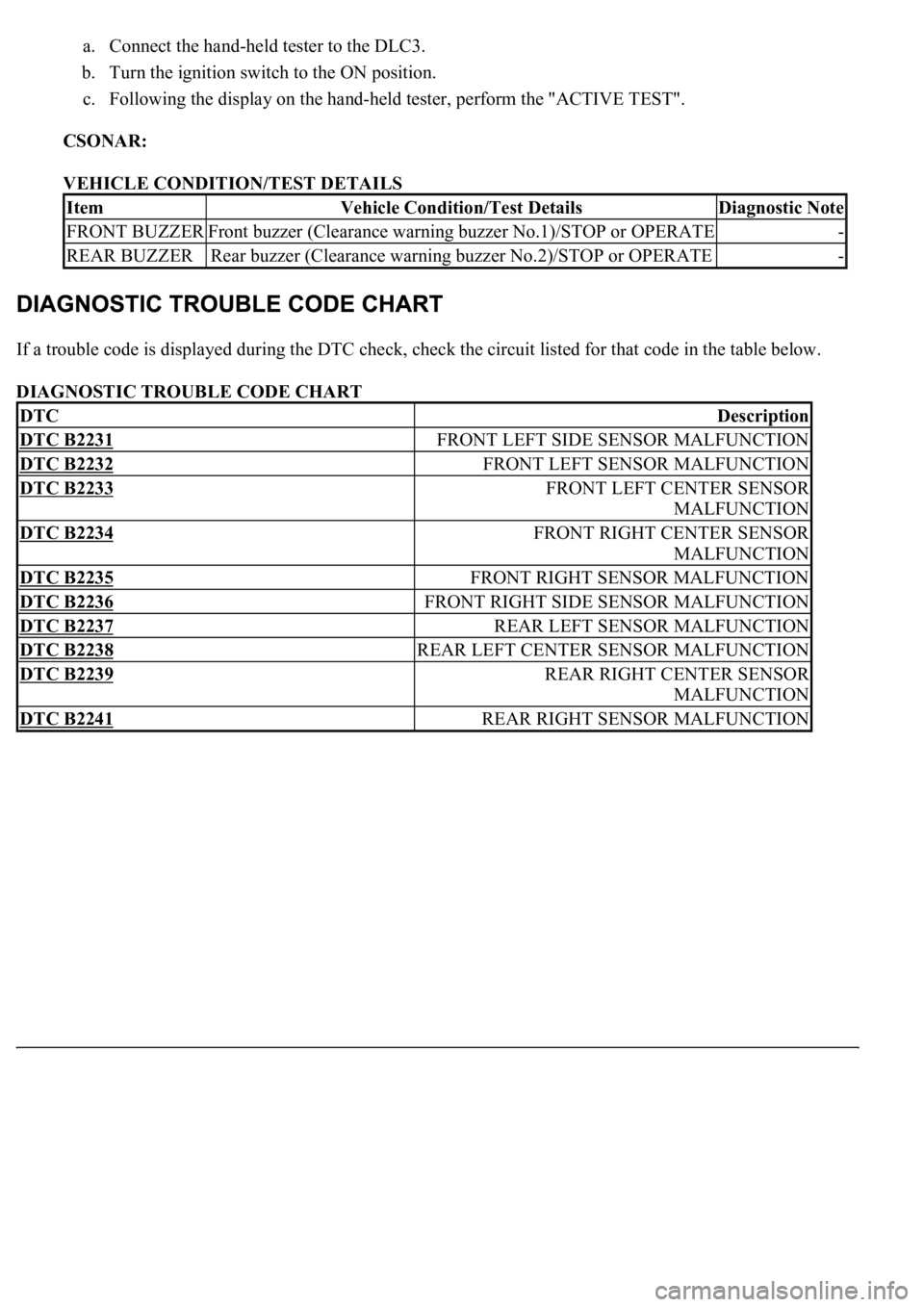
a. Connect the hand-held tester to the DLC3.
b. Turn the ignition switch to the ON position.
c. Following the display on the hand-held tester, perform the "ACTIVE TEST".
CSONAR:
VEHICLE CONDITION/TEST DETAILS
If a trouble code is displayed during the DTC check, check the circuit listed for that code in the table below.
DIAGNOSTIC TROUBLE CODE CHART
ItemVehicle Condition/Test DetailsDiagnostic Note
FRONT BUZZERFront buzzer (Clearance warning buzzer No.1)/STOP or OPERATE-
REAR BUZZERRear buzzer (Clearance warning buzzer No.2)/STOP or OPERATE-
DTCDescription
DTC B2231FRONT LEFT SIDE SENSOR MALFUNCTION
DTC B2232FRONT LEFT SENSOR MALFUNCTION
DTC B2233FRONT LEFT CENTER SENSOR
MALFUNCTION
DTC B2234FRONT RIGHT CENTER SENSOR
MALFUNCTION
DTC B2235FRONT RIGHT SENSOR MALFUNCTION
DTC B2236FRONT RIGHT SIDE SENSOR MALFUNCTION
DTC B2237REAR LEFT SENSOR MALFUNCTION
DTC B2238REAR LEFT CENTER SENSOR MALFUNCTION
DTC B2239REAR RIGHT CENTER SENSOR
MALFUNCTION
DTC B2241REAR RIGHT SENSOR MALFUNCTION
Page 1528 of 4500
Fig. 18: Diagnostic Trouble Code Chart
Courtesy of TOYOTA MOTOR SALES, U.S.A., INC.
CIRCUIT DESCRIPTION
Ultrasonic sensor consists of a sensor portion that transmits and receives ultrasonic waves and a pre-amplifier
that amplifies them. The ultrasonic sensor outputs the ultrasonic transmission and reception signals to the
clearance warning ECU assy.
Fig. 19: DTC B2231 Detection Condition And Trouble Area Description Chart
Courtesy of TOYOTA MOTOR SALES, U.S.A., INC.