Page 3208 of 4500
CIRCUIT DESCRIPTION
This DTC is output when a key with a key code that has not been registered in the ECU is inserted into the
ignition key cylinder.
UNMATCHED KEY CODE DTC REFERENCE TABLE
INSPECTION PROCEDURE
1.DELETE DTC AND INSERT ALL PRESENTLY AVAILABLE KEYS TO CHECK WHETHER
ENGINE STARTS OR NOT
OK: Engine starts.
NG: REPLACE KEY THAT CANNOT START ENGINE
OK: NO PROBLEM (BECAUSE OF KEY RE-REGISTRATION)
CIRCUIT DESCRIPTION
This DTC is output when a key that does not have a transponder chip is inserted into the ignition key cylinder or
if communication between the key and steering lock ECU is not possible.
Fig. 34: Communication Malfunction Circuit Description
Courtesy of TOYOTA MOTOR SALES, U.S.A., INC.
WIRING DIAGRAM
DTC No.DTC Detection ConditionTrouble Area
B2795Key with unregistered key code is
insertedSmart key
Page 3209 of 4500
Fig. 35: No Communication In Immobilizer System, DTC B2798: Communication Malfunction No. 2
DTC - Wiring Diagram
Courtesy of TOYOTA MOTOR SALES, U.S.A., INC.
INSPECTION PROCEDURE
1.READ DATA LIST USING HAND-HELD TESTER
a. Connect the hand-held tester to the CAN VIM. Then connect the CAN VIM to the DLC3.
b. Turn the ignition switch ON with the key that cannot start the engine.
c. Read the DATA LIST.
Steering lock ECU:
DATA LIST - STEERING LOCK ECU
OK: "UNSET" (Ignition switch ON) appears on the screen.
NG: Go to step 2
OK: REPLACE STEERING LOCK ECU
2.CHECK WHETHER ENGINE STARTS WITH OTHER KEYS
a. Check if the en
gine starts with the vehicle's other keys.
Item
Measurement Item/
Display (Range)
Normal ConditionDiagnostic Note
IMMOBILIZERImmobilizer system
status/ SET or UNSETUNSET: Ignition switch
ON SET: Without key-
Page 3210 of 4500
OK: Engine starts.
NG: Go to step 3
OK: RE-REGISTER OR REPLACE KEY THAT CANNOT START ENGINE
3.CHECK WIRE HARNESS (STEERING LOCK ECU - TRANSPONDER KEY AMPLIFIER)
a. Disconnect the S46 ECU connector.
b. Disconnect the T8 amplifier connector.
c. Measure the resistance of the wire harness side connectors.
Standard:
STEERING LOCK ECU - TRANSPONDER KEY AMPLIFIER - RESISTANCE TABLE
Tester connectionSpecified condition
S46-7 (VC5) - T8-1 (VC5)Below 1 ohms
S46-17 (CODE) - T8-4 (CODE)Below 1 ohms
S46-8 (RXCK) - T8-3 (RXCK)Below 1 ohms
S46-16 (TXCT) - T8-1 (TXCT)Below 1 ohms
S46-7 (VC5) or T8-1 (VC5) - Body ground10 kohms or higher
S46-17 (CODE) or T8-4 (CODE) - Body ground10 kohms or higher
S46-8 (RXCK) or T8-3 (RXCK) - Body ground10 kohms or higher
S46-16 (TXCT) or T8-5 (TXCT) - Body ground10 kohms or higher
Page 3212 of 4500
Fig. 36: Checking Wire Harness (Steering Lock ECU -Transponder Key Amplifier)
Courtesy of TOYOTA MOTOR SALES, U.S.A., INC.
NG: REPAIR OR REPLACE HARNESS AND CONNECTOR
OK: Go to next step
4.REPLACE TRANSPONDER KEY AMPLIFIER
a. After replacing the transponder key amplifier with a normally functioning amplifier, check that the
engine starts.
OK: Engine starts.
NG: REPLACE STEERING LOCK ECU
OK: END
CIRCUIT DESCRIPTION
This DTC is output when a communication error occurs between the transponder key amplifier and steering
lock ECU. Some possible reasons for the communication error are: 1) 2 or more smart keys are positioned too
close together, or 2) noise is occurring in the communication line. Follow the inspection procedure below.
Fig. 37: Communication Malfunction No. 1 Circuit Description
Courtesy of TOYOTA MOTOR SALES, U.S.A., INC.
WIRING DIAGRAM
Page 3214 of 4500
Fig. 39: Checking Keys
Courtesy of TOYOTA MOTOR SALES, U.S.A., INC.
B: Go to step 3
A: Go to next step
2.CHECK FOR DTCS
a. Separate the keys from each other. Or, remove the key ring.
b. Delete the DTC (See DTC CHECK/CLEAR
).
c. Insert a key into the ignition key cylinder. Remove it. Repeat for all the other keys.
d. Check that no code is output.
NG: Go to step 3
OK: END
3.CHECK STEERING LOCK ECU
Page 3215 of 4500
a. Using an oscilloscope or the hand-held tester check the waveform between the terminals of the T8
amplifier connector and S46 ECU connector. The waveform should be similar to the illustration on
the left.
OK: No noise is present (see Fig. 40
).
Fig. 40: Checking If Noise Is Present
Courtesy of TOYOTA MOTOR SALES, U.S.A., INC.
STEERING LOCK ECU - WAVEFORM TABLE
TOOL SETTING REFERENCE TABLE
NG: FIND CAUSE OF NOISE AND REMOVE IT
OK: Go to next step
4.CHECK WIRE HARNESS (STEERING LOCK ECU - TRANSPONDER KEY AMPLIFIER)
a. Disconnect the S46 ECU connector.
b. Disconnect the T8 amplifier connector.
c. Measure the resistance of the terminals of the connectors.
Tester connectionSpecified condition
S46-17 (CODE) - T8-4 (CODE)No noise is present
Tool Setting10 V/DIV., 20 ms/DIV.
ConditionIgnition switch OFF -> ON
Page 3216 of 4500
Standard:
STEERING LOCK ECU - TRANSPONDER KEY AMPLIFIER - RESISTANCE TABLE
Tester connectionSpecified condition
S46-17 (CODE) - T8-4 (CODE)Below 1 ohms
Page 3218 of 4500

Fig. 41: Checking Wire Harness (Steering Lock ECU -Transponder Key Amplifier)
Courtesy of TOYOTA MOTOR SALES, U.S.A., INC.
NG: REPAIR OR REPLACE HARNESS AND CONNECTOR
OK: Go to next step
5.CHECK OPERATION OF TRANSPONDER KEY AMPLIFIER
a. After replacing the transponder key amplifier with a normally functioning amplifier, check that the
engine starts.
OK: Engine starts.
NG: REPLACE STEERING LOCK ECU
OK: END
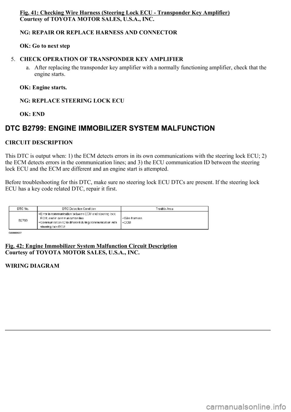
CIRCUIT DESCRIPTION
This DTC is output when: 1) the ECM detects errors in its own communications with the steering lock ECU; 2)
the ECM detects errors in the communication lines; and 3) the ECU communication ID between the steering
lock ECU and the ECM are different and an engine start is attempted.
Before troubleshooting for this DTC, make sure no steering lock ECU DTCs are present. If the steering lock
ECU has a key code related DTC, repair it first.
Fig. 42: Engine Immobilizer System Malfunction Circuit Description
Courtesy of TOYOTA MOTOR SALES, U.S.A., INC.
WIRING DIAGRAM