Page 3168 of 4500
A: Go to next step
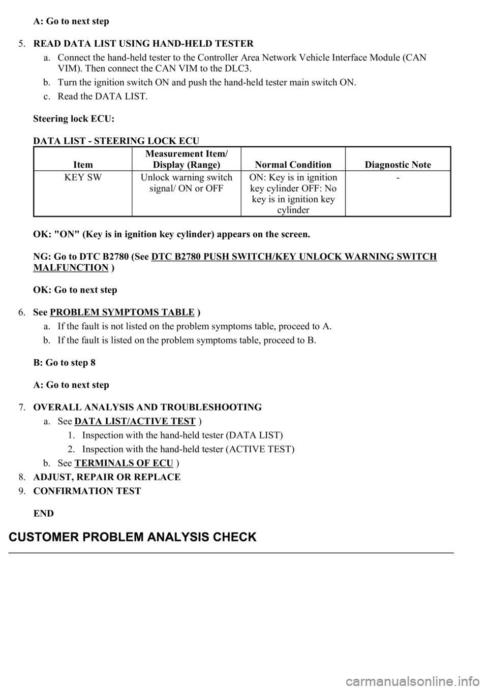
5.READ DATA LIST USING HAND-HELD TESTER
a. Connect the hand-held tester to the Controller Area Network Vehicle Interface Module (CAN
VIM). Then connect the CAN VIM to the DLC3.
b. Turn the ignition switch ON and push the hand-held tester main switch ON.
c. Read the DATA LIST.
Steering lock ECU:
DATA LIST - STEERING LOCK ECU
OK: "ON" (Key is in ignition key cylinder) appears on the screen.
NG: Go to DTC B2780 (See DTC B2780 PUSH SWITCH/KEY UNLOCK WARNING SWITCH
MALFUNCTION )
OK: Go to next step
6.See PROBLEM SYMPTOMS TABLE
)
a. If the fault is not listed on the problem symptoms table, proceed to A.
b. If the fault is listed on the problem symptoms table, proceed to B.
B: Go to step 8
A: Go to next step
7.OVERALL ANALYSIS AND TROUBLESHOOTING
a. See DATA LIST/ACTIVE TEST
)
1. Inspection with the hand-held tester (DATA LIST)
2. Inspection with the hand-held tester (ACTIVE TEST)
b. See TERMINALS OF ECU
)
8.ADJUST, REPAIR OR REPLACE
9.CONFIRMATION TEST
END
Item
Measurement Item/
Display (Range)
Normal ConditionDiagnostic Note
KEY SWUnlock warning switch
signal/ ON or OFFON: Key is in ignition
key cylinder OFF: No
key is in ignition key
cylinder-
Page 3170 of 4500
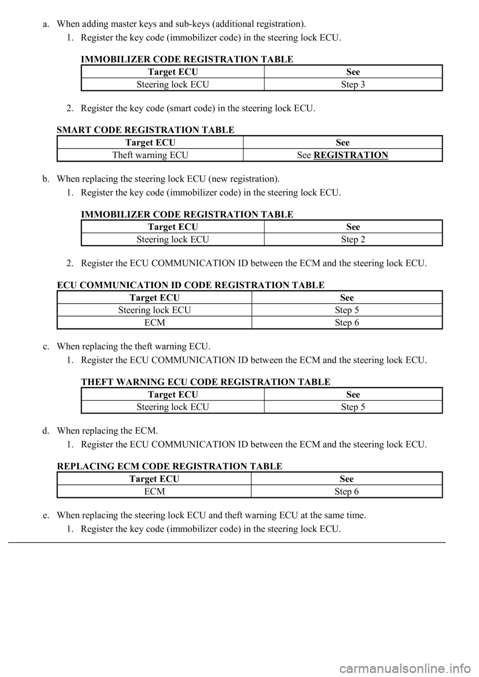
a. When adding master keys and sub-keys (additional registration).
1. Register the key code (immobilizer code) in the steering lock ECU.
IMMOBILIZER CODE REGISTRATION TABLE
2. Register the key code (smart code) in the steering lock ECU.
SMART CODE REGISTRATION TABLE
b. When replacing the steering lock ECU (new registration).
1. Register the key code (immobilizer code) in the steering lock ECU.
IMMOBILIZER CODE REGISTRATION TABLE
2. Register the ECU COMMUNICATION ID between the ECM and the steering lock ECU.
ECU COMMUNICATION ID CODE REGISTRATION TABLE
c. When replacing the theft warning ECU.
1. Register the ECU COMMUNICATION ID between the ECM and the steering lock ECU.
THEFT WARNING ECU CODE REGISTRATION TABLE
d. When replacing the ECM.
1. Register the ECU COMMUNICATION ID between the ECM and the steering lock ECU.
REPLACING ECM CODE REGISTRATION TABLE
e. When replacing the steering lock ECU and theft warning ECU at the same time.
1. Register the key code (immobilizer code) in the steering lock ECU.
Target ECUSee
Steering lock ECUStep 3
Target ECUSee
Theft warning ECUSee REGISTRATION
Target ECUSee
Steering lock ECUStep 2
Target ECUSee
Steering lock ECUStep 5
ECMStep 6
Target ECUSee
Steering lock ECUStep 5
Target ECUSee
ECMStep 6
Page 3171 of 4500
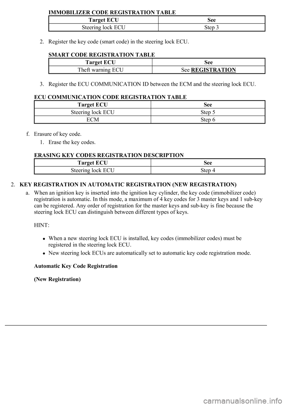
IMMOBILIZER CODE REGISTRATION TABLE
2. Register the key code (smart code) in the steering lock ECU.
SMART CODE REGISTRATION TABLE
3. Register the ECU COMMUNICATION ID between the ECM and the steering lock ECU.
ECU COMMUNICATION CODE REGISTRATION TABLE
f. Erasure of key code.
1. Erase the key codes.
ERASING KEY CODES REGISTRATION DESCRIPTION
2.KEY REGISTRATION IN AUTOMATIC REGISTRATION (NEW REGISTRATION)
a. When an ignition key is inserted into the ignition key cylinder, the key code (immobilizer code)
registration is automatic. In this mode, a maximum of 4 key codes for 3 master keys and 1 sub-key
can be registered. Any order of registration for the master keys and sub-key is fine because the
steering lock ECU can distinguish between different types of keys.
HINT:
When a new steering lock ECU is installed, key codes (immobilizer codes) must be
registered in the steering lock ECU.
New steering lock ECUs are automatically set to automatic key code registration mode.
Automatic Key Code Registration
(New Registration)
Target ECUSee
Steering lock ECUStep 3
Target ECUSee
Theft warning ECUSee REGISTRATION
Target ECUSee
Steering lock ECUStep 5
ECMStep 6
Target ECUSee
Steering lock ECUStep 4
Page 3184 of 4500
Fig. 14: Identifying Waveform 3
Courtesy of TOYOTA MOTOR SALES, U.S.A., INC.
2.CHECK STEERING LOCK ECU
Page 3185 of 4500
Fig. 15: Checking Steering Lock ECU
Courtesy of TOYOTA MOTOR SALES, U.S.A., INC.
a. Disconnect the S46 ECU connector.
b. Measure the voltage and resistance of the wire harness side connector.
Standard:
STEERING LOCK ECU - VOLTAGE TABLE
Symbols
(Terminal No.)
Wiring Color
Terminal
Description
Condition
Specified
Condition
AGND (S46-18) -
Body groundV - Body groundGroundAlwaysBelow 1 ohms
CPUB (S46-1) -
GND (S46-9)V-Y - W-BBatteryAlways10 to 14 V
IG2 (S46-2) -
AGND (S46-18)B - VIgnition switchIgnition switch
OFF -> ONOV -> 10 to 14 V
Page 3186 of 4500
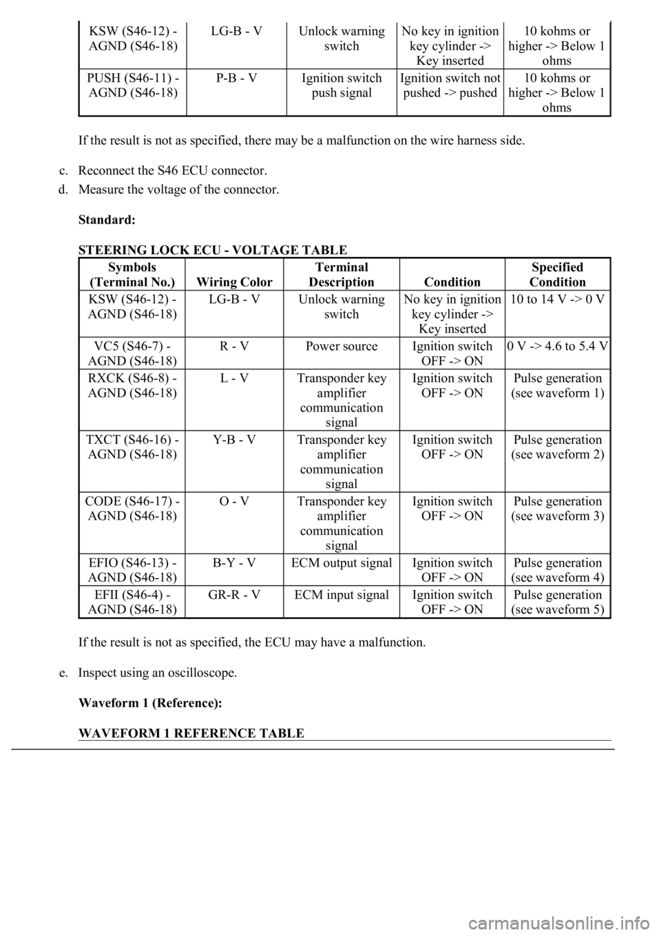
If the result is not as specified, there may be a malfunction on the wire harness side.
c. Reconnect the S46 ECU connector.
d. Measure the voltage of the connector.
Standard:
STEERING LOCK ECU - VOLTAGE TABLE
If the result is not as specified, the ECU may have a malfunction.
e. Inspect using an oscilloscope.
Waveform 1 (Reference):
WAVEFORM 1 REFERENCE TABLE
KSW (S46-12) -
AGND (S46-18)LG-B - VUnlock warning
switchNo key in ignition
key cylinder ->
Key inserted10 kohms or
higher -> Below 1
ohms
PUSH (S46-11) -
AGND (S46-18)P-B - VIgnition switch
push signalIgnition switch not
pushed -> pushed10 kohms or
higher -> Below 1
ohms
Symbols
(Terminal No.)
Wiring Color
Terminal
Description
Condition
Specified
Condition
KSW (S46-12) -
AGND (S46-18)LG-B - VUnlock warning
switchNo key in ignition
key cylinder ->
Key inserted10 to 14 V -> 0 V
VC5 (S46-7) -
AGND (S46-18)R - VPower sourceIgnition switch
OFF -> ON0 V -> 4.6 to 5.4 V
RXCK (S46-8) -
AGND (S46-18)L - VTransponder key
amplifier
communication
signalIgnition switch
OFF -> ONPulse generation
(see waveform 1)
TXCT (S46-16) -
AGND (S46-18)Y-B - VTransponder key
amplifier
communication
signalIgnition switch
OFF -> ONPulse generation
(see waveform 2)
CODE (S46-17) -
AGND (S46-18)O - VTransponder key
amplifier
communication
signalIgnition switch
OFF -> ONPulse generation
(see waveform 3)
EFIO (S46-13) -
AGND (S46-18)B-Y - VECM output signalIgnition switch
OFF -> ONPulse generation
(see waveform 4)
EFII (S46-4) -
AGND (S46-18)GR-R - VECM input signalIgnition switch
OFF -> ONPulse generation
(see waveform 5)
Page 3192 of 4500
Standard:
ECM CONNECTORS - VOLTAGE AND RESISTANCE TABLE
If the result is not as specified, there may be a malfunction on the wire harness side.
c. Inspect using an oscilloscope.
Waveform 1 (Reference):
WAVEFORM 1 REFERENCE TABLE
Symbols
(Terminal No.)
Wiring Color
Terminal
Description
Condition
Specified
Condition
IMI (E2-6) - E01
(E4-2)GR-G - W-BSteering lock ECU
input signalNo key in ignition
key cylinder ->
Key insertedPulse generation
(see waveform 1)
IMO (E2-7) - E01
(E4-2)GR-R - W-BSteering lock ECU
output signalNo key in ignition
key cylinder ->
Key insertedPulse generation
(see waveform 2)
E01 (E4-2) - Body
groundW-B - Body
groundGroundAlwaysBelow 1 ohms
TerminalIMI - GND
Tool Setting10 V/DIV., 500 ms/DIV.
ConditionNo key in ignition key cylinder -> Key inserted
Page 3198 of 4500
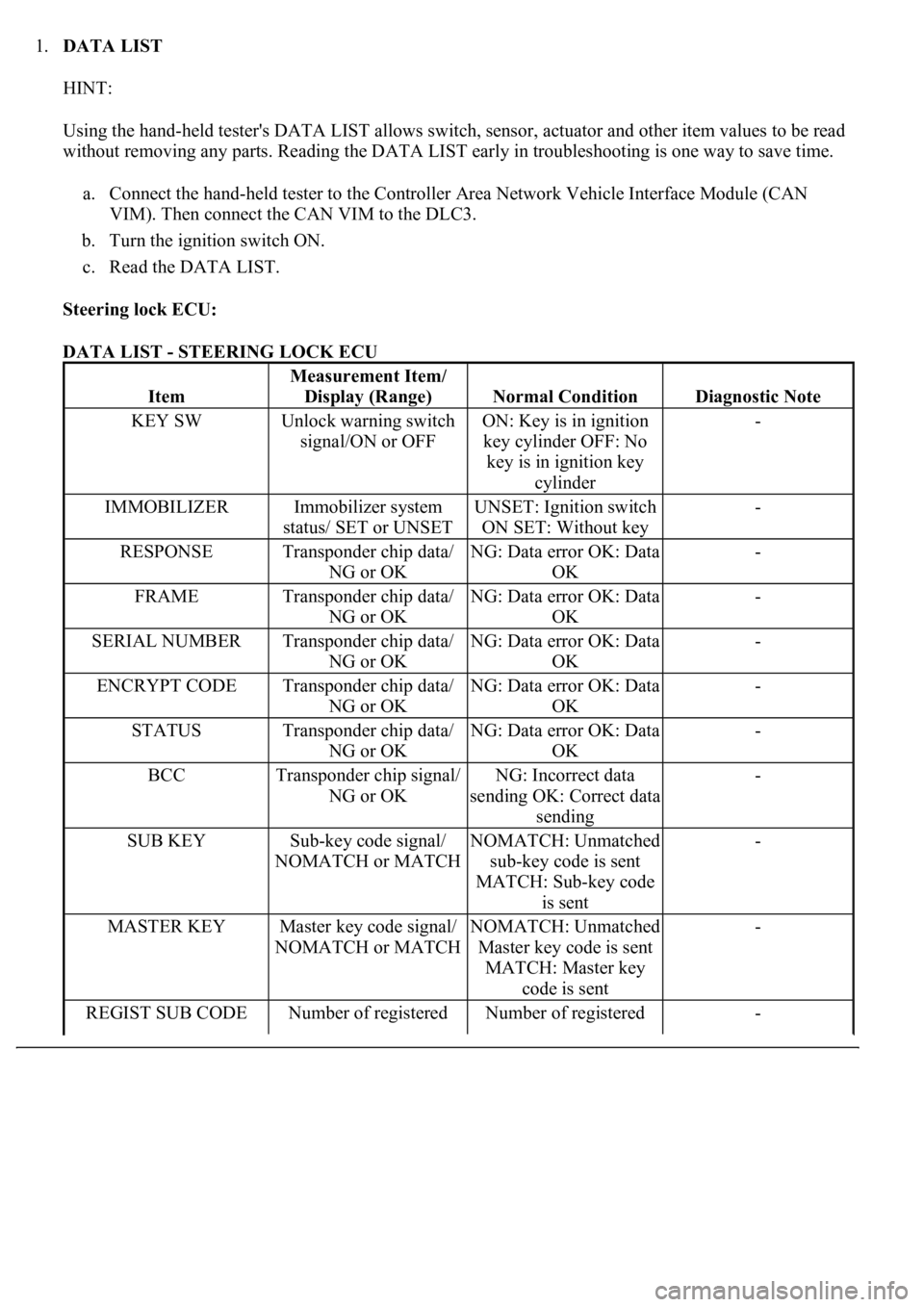
1.DATA LIST
HINT:
Using the hand-held tester's DATA LIST allows switch, sensor, actuator and other item values to be read
without removing any parts. Reading the DATA LIST early in troubleshooting is one way to save time.
a. Connect the hand-held tester to the Controller Area Network Vehicle Interface Module (CAN
VIM). Then connect the CAN VIM to the DLC3.
b. Turn the ignition switch ON.
c. Read the DATA LIST.
Steering lock ECU:
DATA LIST - STEERING LOCK ECU
Item
Measurement Item/
Display (Range)
Normal ConditionDiagnostic Note
KEY SWUnlock warning switch
signal/ON or OFFON: Key is in ignition
key cylinder OFF: No
key is in ignition key
cylinder-
IMMOBILIZERImmobilizer system
status/ SET or UNSETUNSET: Ignition switch
ON SET: Without key-
RESPONSETransponder chip data/
NG or OKNG: Data error OK: Data
OK-
FRAMETransponder chip data/
NG or OKNG: Data error OK: Data
OK-
SERIAL NUMBERTransponder chip data/
NG or OKNG: Data error OK: Data
OK-
ENCRYPT CODETransponder chip data/
NG or OKNG: Data error OK: Data
OK-
STATUSTransponder chip data/
NG or OKNG: Data error OK: Data
OK-
BCCTransponder chip signal/
NG or OKNG: Incorrect data
sending OK: Correct data
sending-
SUB KEYSub-key code signal/
NOMATCH or MATCHNOMATCH: Unmatched
sub-key code is sent
MATCH: Sub-key code
is sent-
MASTER KEYMaster key code signal/
NOMATCH or MATCHNOMATCH: Unmatched
Master key code is sent
MATCH: Master key
code is sent-
REGIST SUB CODENumber of registered Number of registered -