Page 155 of 4500
CIRCUIT DESCRIPTION
If the ECU stores DTC, the VSC warning light comes on in the combination meter.
The skid control ECU is connected to the combination meter via CAN and MPX communications.
WIRING DIAGRAM
Page 156 of 4500
Fig. 116: VSC Warning Light Wiring Diagram
Courtesy of TOYOTA MOTOR SALES, U.S.A., INC.
INSPECTION PROCEDURE
1.CHECK DTC
a. Is DTC output for ABS, VSC, CAN and/or MPX?
Page 159 of 4500
Fig. 118: Identifying Skid Control ECU Terminals
Courtesy of TOYOTA MOTOR SALES, U.S.A., INC.
OK: REPLACE ABS & TRACTION ACTUATOR ASSY (SEE REPLACEMENT
)
CIRCUIT DESCRIPTION
If the ECU stores DTC, the VSC warning light comes on in the combination meter.
The skid control ECU is connected to the combination meter via CAN and MPX communications.
WIRING DIAGRAM
Page 160 of 4500
Fig. 119: VSC Warning Light Wiring Diagram
Courtesy of TOYOTA MOTOR SALES, U.S.A., INC.
INSPECTION PROCEDURE
1.INSPECT CAN COMMUNICATION SYSTEM
a. Is the DTC output for CAN communication s
ystem?
Page 161 of 4500

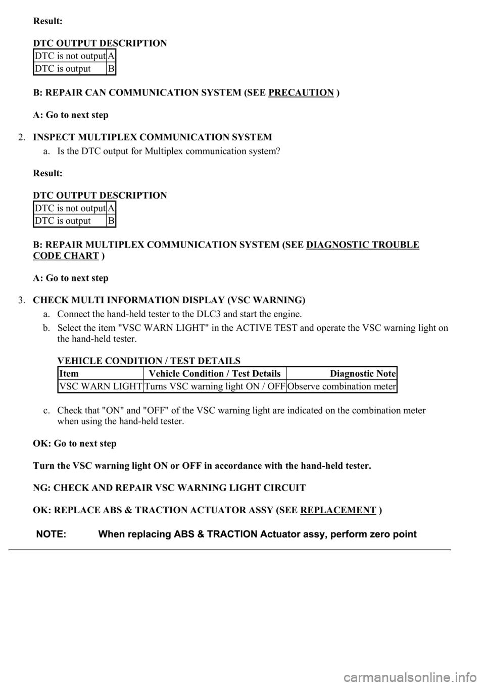
Result:
DTC OUTPUT DESCRIPTION
B: REPAIR CAN COMMUNICATION SYSTEM (SEE PRECAUTION
)
A: Go to next step
2.INSPECT MULTIPLEX COMMUNICATION SYSTEM
a. Is the DTC output for Multiplex communication system?
Result:
DTC OUTPUT DESCRIPTION
B: REPAIR MULTIPLEX COMMUNICATION SYSTEM (SEE DIAGNOSTIC TROUBLE
CODE CHART )
A: Go to next step
3.CHECK MULTI INFORMATION DISPLAY (VSC WARNING)
a. Connect the hand-held tester to the DLC3 and start the engine.
b. Select the item "VSC WARN LIGHT" in the ACTIVE TEST and operate the VSC warning light on
the hand-held tester.
VEHICLE CONDITION / TEST DETAILS
c. Check that "ON" and "OFF" of the VSC warning light are indicated on the combination meter
when using the hand-held tester.
OK: Go to next step
Turn the VSC warning light ON or OFF in accordance with the hand-held tester.
NG: CHECK AND REPAIR VSC WARNING LIGHT CIRCUIT
OK: REPLACE ABS & TRACTION ACTUATOR ASSY (SEE REPLACEMENT
)
DTC is not outputA
DTC is outputB
DTC is not outputA
DTC is outputB
ItemVehicle Condition / Test DetailsDiagnostic Note
VSC WARN LIGHTTurns VSC warning light ON / OFFObserve combination meter
Page 162 of 4500
CIRCUIT DESCRIPTION
The BRAKE warning light comes on when the brake fluid is insufficient, the parking brake is applied or the
EBD is defective.
The skid control ECU is connected to the combination meter via CAN and Multiplex communications.
The pad wear indicator is installed to the brake pad (right side).
If the wear indicator wire is open, "Brake Wear" appears on the multi-information display, which indicates that
the pad must be replaced.
WIRING DIAGRAM
Page 163 of 4500
Fig. 120: Brake Warning Light Wiring Diagram (1 Of 2)
Courtesy of TOYOTA MOTOR SALES, U.S.A., INC.
Page 164 of 4500
Fig. 121: Brake Warning Light Wiring Diagram (2 Of 2)
Courtesy of TOYOTA MOTOR SALES, U.S.A., INC.