Page 1782 of 4500
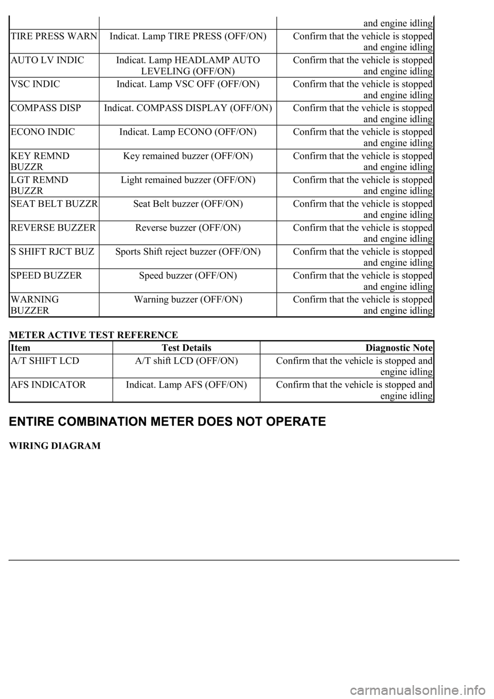
METER ACTIVE TEST REFERENCE
WIRING DIAGRAM
and engine idling
TIRE PRESS WARNIndicat. Lamp TIRE PRESS (OFF/ON)Confirm that the vehicle is stopped
and engine idling
AUTO LV INDICIndicat. Lamp HEADLAMP AUTO
LEVELING (OFF/ON)Confirm that the vehicle is stopped
and engine idling
VSC INDICIndicat. Lamp VSC OFF (OFF/ON)Confirm that the vehicle is stopped
and engine idling
COMPASS DISPIndicat. COMPASS DISPLAY (OFF/ON)Confirm that the vehicle is stopped
and engine idling
ECONO INDICIndicat. Lamp ECONO (OFF/ON)Confirm that the vehicle is stopped
and engine idling
KEY REMND
BUZZRKey remained buzzer (OFF/ON)Confirm that the vehicle is stopped
and engine idling
LGT REMND
BUZZRLight remained buzzer (OFF/ON)Confirm that the vehicle is stopped
and engine idling
SEAT BELT BUZZRSeat Belt buzzer (OFF/ON)Confirm that the vehicle is stopped
and engine idling
REVERSE BUZZERReverse buzzer (OFF/ON)Confirm that the vehicle is stopped
and engine idling
S SHIFT RJCT BUZSports Shift reject buzzer (OFF/ON)Confirm that the vehicle is stopped
and engine idling
SPEED BUZZERSpeed buzzer (OFF/ON)Confirm that the vehicle is stopped
and engine idling
WARNING
BUZZERWarning buzzer (OFF/ON)Confirm that the vehicle is stopped
and engine idling
ItemTest DetailsDiagnostic Note
A/T SHIFT LCDA/T shift LCD (OFF/ON)Confirm that the vehicle is stopped and
engine idling
AFS INDICATORIndicat. Lamp AFS (OFF/ON)Confirm that the vehicle is stopped and
engine idling
Page 1850 of 4500
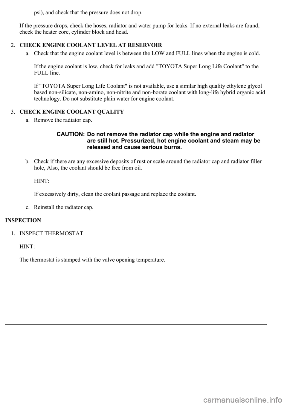
psi), and check that the pressure does not drop.
If the pressure drops, check the hoses, radiator and water pump for leaks. If no external leaks are found,
check the heater core, cylinder block and head.
2.CHECK ENGINE COOLANT LEVEL AT RESERVOIR
a. Check that the engine coolant level is between the LOW and FULL lines when the engine is cold.
If the engine coolant is low, check for leaks and add "TOYOTA Super Long Life Coolant" to the
FULL line.
If "TOYOTA Super Long Life Coolant" is not available, use a similar high quality ethylene glycol
based non-silicate, non-amino, non-nitrite and non-borate coolant with long-life hybrid organic acid
technology. Do not substitute plain water for engine coolant.
3.CHECK ENGINE COOLANT QUALITY
a. Remove the radiator cap.
b. Check if there are any excessive deposits of rust or scale around the radiator cap and radiator filler
hole, Also, the coolant should be free from oil.
HINT:
If excessively dirty, clean the coolant passage and replace the coolant.
c. Reinstall the radiator cap.
INSPECTION
1. INSPECT THERMOSTAT
HINT:
The thermostat is stamped with the valve openin
g temperature.
Page 1963 of 4500
15. Return the reflector to the original position and read the current angle.
DIVERGENCE OF BEAM AXIS TABLE
HINT:
When the values displayed on the screen are normal, the values are within the above range. If the
value is out of range, check the installation condition of the bumper reinforcement, etc.
16. Turn the headlamp dimmer switch to the TAIL position.
17. Press the "ENTER" key.
Fig. 16: Identifying "ENTER" Key
UPPER/LOWER SIDE-2° TO +2°
RIGHT/LEFT SIDE-4° TO +4°
Page 2008 of 4500
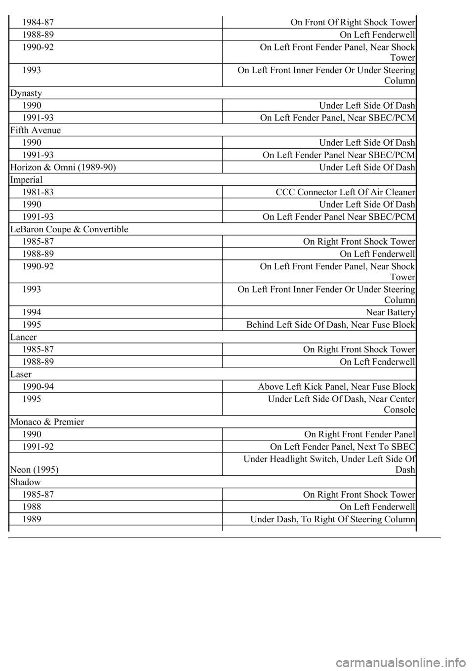
1984-87On Front Of Right Shock Tower
1988-89On Left Fenderwell
1990-92On Left Front Fender Panel, Near Shock
Tower
1993On Left Front Inner Fender Or Under Steering
Column
Dynasty
1990Under Left Side Of Dash
1991-93On Left Fender Panel, Near SBEC/PCM
Fifth Avenue
1990Under Left Side Of Dash
1991-93On Left Fender Panel Near SBEC/PCM
Horizon & Omni (1989-90)Under Left Side Of Dash
Imperial
1981-83CCC Connector Left Of Air Cleaner
1990Under Left Side Of Dash
1991-93On Left Fender Panel Near SBEC/PCM
LeBaron Coupe & Convertible
1985-87On Right Front Shock Tower
1988-89On Left Fenderwell
1990-92On Left Front Fender Panel, Near Shock
Tower
1993On Left Front Inner Fender Or Under Steering
Column
1994Near Battery
1995Behind Left Side Of Dash, Near Fuse Block
Lancer
1985-87On Right Front Shock Tower
1988-89On Left Fenderwell
Laser
1990-94Above Left Kick Panel, Near Fuse Block
1995Under Left Side Of Dash, Near Center
Console
Monaco & Premier
1990On Right Front Fender Panel
1991-92On Left Fender Panel, Next To SBEC
Neon (1995)
Under Headlight Switch, Under Left Side Of
Dash
Shadow
1985-87On Right Front Shock Tower
1988On Left Fenderwell
1989Under Dash, To Right Of Steering Column
Page 2177 of 4500
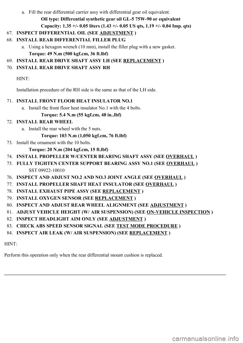
a. Fill the rear differential carrier assy with differential gear oil equivalent.
Oil type: Differential synthetic gear oil GL-5 75W-90 or equivalent
Capacity: 1.35 +/- 0.05 liters (1.43 +/- 0.05 US qts, 1.19 +/- 0.04 Imp. qts)
67.INSPECT DIFFERENTIAL OIL (SEE ADJUSTMENT
)
68.INSTALL REAR DIFFERENTIAL FILLER PLUG
a. Using a hexagon wrench (10 mm), install the filler plug with a new gasket.
Torque: 49 N.m (500 kgf.cm, 36 ft.lbf)
69.INSTALL REAR DRIVE SHAFT ASSY LH (SEE REPLACEMENT
)
70.INSTALL REAR DRIVE SHAFT ASSY RH
HINT:
Installation procedure of the RH side is the same as that of the LH side.
71.INSTALL FRONT FLOOR HEAT INSULATOR NO.1
a. Install the front floor heat insulator No.1 with the 4 bolts.
Torque: 5.4 N.m (55 kgf.cm, 48 in..lbf)
72.INSTALL REAR WHEEL
a. Install the rear wheel with the 5 nuts.
Torque: 103 N.m (1,050 kgf.cm, 76 ft.lbf)
73. Install the ornament with the 10 bolts.
Torque: 20 N.m (204 kgf.cm, 15 ft.lbf)
74.INSTALL PROPELLER W/CENTER BEARING SHAFT ASSY (SEE OVERHAUL
)
75.FULLY TIGHTEN CENTER SUPPORT BEARING ASSY NO.1 (SEE OVERHAUL
)
SST 09922-10010
76.INSPECT AND ADJUST NO.2 AND NO.3 JOINT ANGLE (SEE OVERHAUL
)
77.INSTALL PROPELLER SHAFT HEAT INSULATOR (SEE OVERHAUL
)
78.INSTALL EXHAUST PIPE ASSY (SEE REPLACEMENT
)
79.INSTALL OXYGEN SENSOR (SEE REPLACEMENT
)
80.INSPECT AND ADJUST REAR WHEEL ALIGNMENT (SEE ADJUSTMENT
)
81.ADJUST VEHICLE HEIGHT (W/ AIR SUSPENSION) (SEE ON
-VEHICLE INSPECTION )
82.INSPECT HEADLIGHT AIM ONLY (SEE ADJUSTMENT
)
83.CHECK ABS SPEED SENSOR SIGNAL (SEE TEST MODE PROCEDURE
)
84.INSPECT AIR LEAK (W/ AIR SUSPENSION) (SEE REPLACEMENT
)
HINT:
Perform this operation onl
y when the rear differential mount cushion is replaced.
Page 2364 of 4500
b. Using a brass bar or an equivalent to hold, turn the wheel nut to pull the hub bolt until the underside
of the hub bolt head touches the axle hub.
Fig. 58: Installing Front Axle LH Hub Bolt
Courtesy of TOYOTA MOTOR SALES, U.S.A., INC.
6.INSTALL FRONT DISC (See step 15 on OVERHAUL
)
7.INSTALL FRONT DISC BRAKE CALIPER ASSY LH (See REPLACEMENT
)
8.INSTALL FRONT WHEEL LH
Torque: 103 N.m (1,050 kgf.cm, 76 ft.lbf)
REPLACEMENT
HINT:
See COMPONENTS
<00380056004800030057004b00480003005600440050004800030053005500520046004800470058005500480056000300490052005500030057004b004800030035002b00030056004c0047004800030044005100470003002f002b00030056004c004700
4800110003[
Page 2391 of 4500
Fig. 85: Aligning Matchmarks
Courtesy of TOYOTA MOTOR SALES, U.S.A., INC.
33.INSTALL REAR TIRE
Torque: 103 N.m (1,050 kgf.cm, 76 ft.lbf)
34.ADJUST VEHICLE HEIGHT (W/ AIR SUSPENSION) (See ON
-VEHICLE INSPECTION )
35.INSPECT HEADLIGHT AIM ONLY (See ADJUSTMENT
)
36.INSPECT AND ADJUST REAR WHEEL ALIGNMENT (See ADJUSTMENT
)
37.CHECK ABS SPEED SENSOR SIGNAL (See TEST MODE PROCEDURE
)
REPLACEMENT
HINT:
See COMPONENTS
<00380056004800030057004b00480003005600440050004800030053005500520046004800470058005500480056000300490052005500030057004b004800030035002b00030056004c0047004800030044005100470003002f002b00030056004c004700
4800110003[
Page 2408 of 4500
42.ADJUST PARKING BRAKE PEDAL TRAVEL (See step 5 on ADJUSTMENT )
43.INSTALL SPEED SENSOR REAR LH
a. Install the speed sensor with the bolt.
Torque: 8.0 N.m (82 kgf.cm, 71 in.lbf)
44.INSTALL REAR DISC (See step 16 on OVERHAUL
)
45.ADJUST PARKING BRAKE SHOE CLEARANCE (See step 21 on OVERHAUL
)
46.INSTALL REAR DISC BRAKE CALIPER ASSY LH (See step 20 on REPLACEMENT
)
47.INSTALL REAR AXLE SHAFT NUT (See REPLACEMENT
)
48.INSPECT AXLE HUB BEARING LOOSENESS (See ON
-VEHICLE INSPECTION )
49.INSPECT AXLE HUB BEARING RUNOUT (See ON
-VEHICLE INSPECTION )
50.STABILIZE SUSPENSION (See step 23 on REPLACEMENT
)
51.FULLY TIGHTEN SHOCK ABSORBER ASSY REAR LH
a. Fully tighten the shock absorber assy LH with the new nut.
Torque: 70 N.m (714 kgf.cm, 52 ft.lbf)
52.INSTALL REAR TIRE
Torque: 103 N.m (1,050 kgf.cm, 76 ft.lbf)
53.ADJUST VEHICLE HEIGHT (W/ AIR SUSPENSION) (See ON
-VEHICLE INSPECTION )
54.INSPECT HEADLIGHT AIM ONLY (See ADJUSTMENT
)
55.INSPECT AND ADJUST REAR WHEEL ALIGNMENT (See ADJUSTMENT
)
56.CHECK ABS SPEED SENSOR SIGNAL (See TEST MODE PROCEDURE
)
REPLACEMENT
HINT:
See COMPONENTS
Use the same procedures for the RH side and LH side.
The procedures listed below are for the LH side.
1.REMOVE REAR TIRE
2.REMOVE REAR DISC BRAKE CALIPER ASSY LH (See REPLACEMENT
)
3.REMOVE REAR DISC (See step 15 on OVERHAUL
)
4.REMOVE REAR AXLE LH HUB BOLT
a. Using SST and a screwdriver or an equivalent to hold, remove the hub bolt.
SST 09628-10011