Page 4178 of 4500

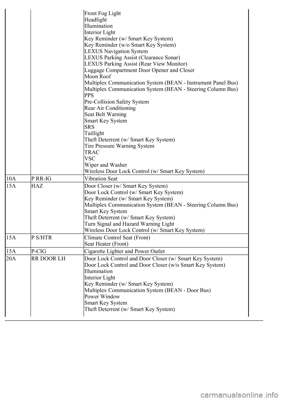
Front Fog Light
Headlight
Illumination
Interior Light
Key Reminder (w/ Smart Key System)
Key Reminder (w/o Smart Key System)
LEXUS Navigation System
LEXUS Parking Assist (Clearance Sonar)
LEXUS Parking Assist (Rear View Monitor)
Luggage Compartment Door Opener and Closer
Moon Roof
Multiplex Communication System (BEAN - Instrument Panel Bus)
Multiplex Communication System (BEAN - Steering Column Bus)
PPS
Pre-Collision Safety System
Rear Air Conditioning
Seat Belt Warning
Smart Key System
SRS
Taillight
Theft Deterrent (w/ Smart Key System)
Tire Pressure Warning System
TRAC
VSC
Wiper and Washer
Wireless Door Lock Control (w/ Smart Key System)
10AP RR-IGVibration Seat
15AHAZDoor Closer (w/ Smart Key System)
Door Lock Control (w/ Smart Key System)
Key Reminder (w/ Smart Key System)
Multiplex Communication System (BEAN - Steering Column Bus)
Smart Key System
Theft Deterrent (w/ Smart Key System)
Turn Signal and Hazard Warning Light
Wireless Door Lock Control (w/ Smart Key System)
15AP S/HTRClimate Control Seat (Front)
Seat Heater (Front)
15AP-CIGCigarette Lighter and Power Outlet
20ARR DOOR LHDoor Lock Control and Door Closer (w/ Smart Key System)
Door Lock Control and Door Closer (w/o Smart Key System)
Illumination
Interior Light
Key Reminder (w/ Smart Key System)
Multiplex Communication System (BEAN - Door Bus)
Power Window
Smart Key System
Theft Deterrent (w/ Smart Key System)
Page 4258 of 4500
Installation is in the reverse order of removal.
See COMPONENTS .
1.DISCONNECT NEGATIVE TERMINAL CABLE FROM BATTERY
2.REMOVE FRONT DOOR SCUFF PLATE LH (See REPLACEMENT
)
3.REMOVE FRONT PILLAR GARNISH LH (See step 33 in REPLACEMENT
)
4.REMOVE INSTRUMENT PANEL UNDER COVER SUB-ASSY NO. 2 (See step 21 in
REPLACEMENT
)
5.REMOVE INSTRUMENT PANEL GARNISH SUB-ASSY RH (See step 22 in REPLACEMENT
)
6.REMOVE GLOVE COMPARTMENT DOOR ASSY W/ INSTRUMENT PANEL AIRBAG ASSY
LOWER NO. 2 (See step 25 in REPLACEMENT
)
7.REMOVE AIR SUSPENSION AND HEADLIGHT BEAM LEVEL CONTROL ECU
a. Disconnect the connectors.
b. Remove the 2 nuts and air suspension and headlight beam level control ECU.
8.REMOVE BLOWER ASSY
a. Disconnect the connectors.
b. Remove the nut and 3 bolts.
c. Remove the blower assy.
Page 4339 of 4500
4.REMOVE OIL LEVEL GAGE SUB-ASSY (See step 8 in REPLACEMENT )
5.REMOVE IGNITION COIL ASSY
a. Disconnect the ignition coil connector.
b. Remove the bolt and pull out the ignition coil.
Fig. 12: Removing Ignition Coil Assy
Courtesy of TOYOTA MOTOR SALES, U.S.A., INC.
6.INSTALL IGNITION COIL ASSY
a. Connect a new ignition coil to the spark plug, attach the ignition coil to the cylinder head cover,
and install the bolt.
Torque: 7.5 N.m (76 kgf.cm, 66 in.lbf)
b. Connect the ignition coil connector.
7.INSTALL OIL LEVEL GAGE SUB-ASSY (See step 27 in REPLACEMENT
)
8.INSTALL INTAKE AIR CONNECTOR PIPE
9.INSTALL V-BANK COVER
10.INSTALL ENGINE ROOM SIDE COVER
Page 4353 of 4500

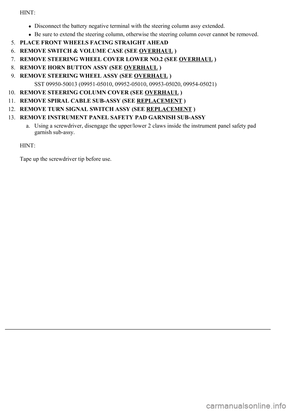
HINT:
Disconnect the battery negative terminal with the steering column assy extended.
Be sure to extend the steering column, otherwise the steering column cover cannot be removed.
5.PLACE FRONT WHEELS FACING STRAIGHT AHEAD
6.REMOVE SWITCH & VOLUME CASE (SEE OVERHAUL
)
7.REMOVE STEERING WHEEL COVER LOWER NO.2 (SEE OVERHAUL
)
8.REMOVE HORN BUTTON ASSY (SEE OVERHAUL
)
9.REMOVE STEERING WHEEL ASSY (SEE OVERHAUL
)
<00360036003700030013001c001c001800130010001800130013001400160003000b0013001c001c00180014001000130018001300140013000f00030013001c001c00180015001000130018001300140013000f00030013001c001c001800160010001300
18001300150013000f00030013001c001c0018001700100013[5021)
10.REMOVE STEERING COLUMN COVER (SEE OVERHAUL
)
11.REMOVE SPIRAL CABLE SUB-ASSY (SEE REPLACEMENT
)
12.REMOVE TURN SIGNAL SWITCH ASSY (SEE REPLACEMENT
)
13.REMOVE INSTRUMENT PANEL SAFETY PAD GARNISH SUB-ASSY
a. Using a screwdriver, disengage the upper/lower 2 claws inside the instrument panel safety pad
garnish sub-assy.
HINT:
Tape up the screwdriver tip before use.
Page 4409 of 4500
Fig. 9: Disconnecting Fuel Pipe Sub-Assy No. 2
Courtesy of TOYOTA MOTOR SALES, U.S.A., INC.
13.REMOVE INTAKE MANIFOLD
a. Remove the bolt and the water by-pass pipe No. 1 and No. 2.
b. Disconnect the vacuum hose for the brake booster.
c. Disconnect the air hose for the power steering.
d. Disconnect the ventilation hose.
e. Disconnect the injector connector.
f. Remove the 6 bolts, 4 nuts and intake manifold.
14.REMOVE INTAKE MANIFOLD TO HEAD GASKET NO. 1
15.INSTALL INTAKE MANIFOLD TO HEAD GASKET NO. 1
a. Install 2 new gaskets to the cylinder head.
HINT:
The white-painted area on each gasket should face up as shown in the illustration.
Page 4410 of 4500
Fig. 10: Installing Intake Manifold To Head Gasket No. 1
Courtesy of TOYOTA MOTOR SALES, U.S.A., INC.
16.INSTALL INTAKE MANIFOLD
a. Install the intake manifold with the 6 bolts and 4 nuts.
Torque: 18 N.m (184 kgf.cm, 13 ft.lbf)
b. Connect the injector connector.
c. Connect the ventilation hose.
d. Connect the air hose for the power steering.
e. Connect the vacuum hose for the brake booster.
f. Install the water by-pass pipe No. 1 and No. 2 with the bolt.
17.CONNECT FUEL PIPE SUB-ASSY NO. 2
a. Using SST, install the fuel main hose.
SST 09023-38401
Page 4449 of 4500

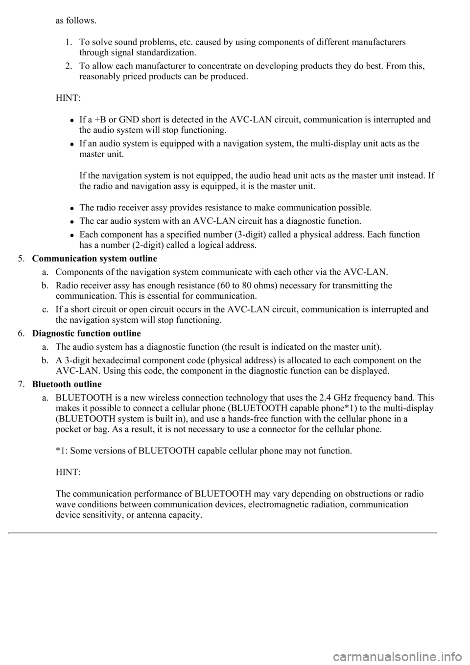
as follows.
1. To solve sound problems, etc. caused by using components of different manufacturers
through signal standardization.
2. To allow each manufacturer to concentrate on developing products they do best. From this,
reasonably priced products can be produced.
HINT:
If a +B or GND short is detected in the AVC-LAN circuit, communication is interrupted and
the audio system will stop functioning.
If an audio system is equipped with a navigation system, the multi-display unit acts as the
master unit.
If the navigation system is not equipped, the audio head unit acts as the master unit instead. I
f
the radio and navigation assy is equipped, it is the master unit.
The radio receiver assy provides resistance to make communication possible.
The car audio system with an AVC-LAN circuit has a diagnostic function.
Each component has a specified number (3-digit) called a physical address. Each function
has a number (2-digit) called a logical address.
5.Communication system outline
a. Components of the navigation system communicate with each other via the AVC-LAN.
b. Radio receiver assy has enough resistance (60 to 80 ohms) necessary for transmitting the
communication. This is essential for communication.
c. If a short circuit or open circuit occurs in the AVC-LAN circuit, communication is interrupted and
the navigation system will stop functioning.
6.Diagnostic function outline
a. The audio system has a diagnostic function (the result is indicated on the master unit).
b. A 3-digit hexadecimal component code (physical address) is allocated to each component on the
AVC-LAN. Using this code, the component in the diagnostic function can be displayed.
7.Bluetooth outline
a. BLUETOOTH is a new wireless connection technology that uses the 2.4 GHz frequency band. This
makes it possible to connect a cellular phone (BLUETOOTH capable phone*1) to the multi-display
(BLUETOOTH system is built in), and use a hands-free function with the cellular phone in a
pocket or bag. As a result, it is not necessary to use a connector for the cellular phone.
*1: Some versions of BLUETOOTH capable cellular phone may not function.
HINT:
The communication performance of BLUETOOTH may vary depending on obstructions or radio
wave conditions between communication devices, electromagnetic radiation, communication
device sensitivit
y, or antenna capacity.
Page 4486 of 4500
Fig. 47: Displaying Vehicle Signal Check Mode Screen
Courtesy of TOYOTA MOTOR SALES, U.S.A., INC.
Screen Description
NAME CONTENTS
HINT:
Only items sending a vehicle signal will be displayed.
This screen is updated once per second when input signals to the vehicle are changed.
3.NAVIGATION CHECK
a. Navigation Check MENU Screen
NameContents
BatteryBattery voltage is displayed.
PKBParking brake ON/OFF state is displayed.
REVReverse signal ON/OFF state is displayed.
IGIG switch ON/OFF state is displayed.
ADIM/TCANBrightness state DIM (with)/ BRIGHT (without) is displayed.
SPEEDThe vehicle speed, displayed in km/h.
TAILTAIL signal (Head lamp dimmer switch) ON/OFF state is displayed.