Page 864 of 4500
Fig. 45: Installing Engine Mounting Insulator Rear No.1 With 4 Bolts
Courtesy of TOYOTA MOTOR SALES, U.S.A., INC.
41.INSTALL AUTOMATIC TRANSMISSION ASSY
a. Install the automatic transmission assy to the engine with the 9 bolts.
Torque:
Bolt A: 14 mm head bolt: 37 N.m (380 kgf.cm, 27 ft.lbf)
Bolt B: 17 mm head bolt: 71 N.m (724 kgf.cm, 52 ft.lbf)
HINT:
Bolt (a) is tightened to the wire harness clamp.
Page 985 of 4500

23.INSTALL OUTER MIRROR SWITCH ASSY
24.INSTALL COIN BOX
25.INSTALL INSTRUMENT PANEL UNDER COVER NO.1 (SEE REPLACEMENT
)
26.INSTALL CLUSTER FINISH PANEL CENTER LOWER
27.INSTALL INSTRUMENT CLUSTER FINISH PANEL END
28.INSTALL SEAT ASSY FR LH
29.INSTALL SEAT TRACK BRACKET COVER INNER FRONT
30.INSTALL SEAT TRACK BRACKET COVER OUTER FRONT
31.INSTALL SEAT TRACK OUTER COVER LH
32.INSTALL SEAT TRACK COVER RH
33.INSTALL SEAT BELT ANCHOR COVER CAP LH
OVERHAUL
1.DISCONNECT BATTERY NEGATIVE TERMINAL
2.PLACE FRONT WHEELS FACING STRAIGHT AHEAD
3.REMOVE SWITCH & VOLUME CASE
4.REMOVE STEERING WHEEL COVER LOWER NO.2
5.REMOVE HORN BUTTON ASSY (SEE OVERHAUL
)
6.REMOVE STEERING WHEEL ASSY (SEE OVERHAUL
)
<00360036003700030013001c001c001800130010001800130013001400160003000b0013001c001c00180014001000130018001300140013000f00030013001c001c00180015001000130018001300140013000f00030013001c001c001800160010001300
18001300150013000f00030013001c001c0018001700100013[5021)
7.REMOVE STEERING COLUMN COVER (SEE OVERHAUL
)
8.REMOVE SPIRAL CABLE SUB-ASSY (SEE REPLACEMENT
)
9.REMOVE TURN SIGNAL SWITCH ASSY (SEE REPLACEMENT
)
10.REMOVE INSTRUMENT CLUSTER FINISH PANEL CENTER LOWER
11.REMOVE INSTRUMENT CLUSTER FINISH PANEL END
12.REMOVE INSTRUMENT PANEL UNDER COVER SUB-ASSY NO.1 (SEE REPLACEMENT
)
13.REMOVE COIN BOX ASSY
14.REMOVE OUTER MIRROR SWITCH ASSY
15.REMOVE INSTRUMENT PANEL SAFETY PAD SUB-ASSY NO.1 (SEE REPLACEMENT
)
16.REMOVE INSTRUMENT PANEL AIR BAG ASSY LOWER NO.1 (SEE REPLACEMENT
)
17.REMOVE INSTRUMENT PANEL UNDER COVER SUB-ASSY NO.2 (SEE REPLACEMENT
)
18.REMOVE INSTRUMENT CLUSTER FINISH PANEL (SEE REPLACEMENT
)
19.REMOVE COMBINATION METER ASSY (SEE OVERHAUL
)
20.REMOVE PUSH ROD PIN
a. Disconnect the stop lamp switch connector and brake pedal load sensing switch connector.
Page 1018 of 4500
Using SST, adjust the booster push rod length until the push rod lightly touches the pin head.
SST 09737-00020
Fig. 51: Adjusting Booster Push Rod Length
Courtesy of TOYOTA MOTOR SALES, U.S.A., INC.
13.INSTALL BRAKE MASTER CYLINDER SUB-ASSY
a. Install the brake master cylinder sub-assy and vacuum check valve bracket with 2 nuts.
Torque: 13 N.m (130 kgf.cm, 9 ft.lbf)
b. Connect the brake fluid level warning switch connector to the master cylinder reservoir.
Page 1086 of 4500
Replace the RH side by using the same procedures as for the LH side.
The procedures listed below are for the LH side.
1.REMOVE REAR SEAT CUSHION ASSY (SEE OVERHAUL
- FIXED TYPE or OVERHAUL -
POWER ADJUSTER TYPE
)
2.REMOVE REAR SEAT HEAD REST ASSY (SEE OVERHAUL
- FIXED TYPE or OVERHAUL -
POWER ADJUSTER TYPE )
3.REMOVE REAR SEATBACK ASSY (SEE OVERHAUL
- FIXED TYPE or OVERHAUL -
POWER ADJUSTER TYPE
)
4.REMOVE REAR WHEEL
5.REMOVE REAR WHEEL HOUSE LH LINER
6.REMOVE SPEED SENSOR REAR LH
a. Disconnect the speed sensor connector, and pull out the speed sensor wire harness with the
grommet.
Fig. 116: Disconnecting Speed Sensor Connector
Courtesy of TOYOTA MOTOR SALES, U.S.A., INC.
b. Remove the nut and bolt and disconnect the speed sensor rear wire harness.
Page 1093 of 4500
Fig. 123: Connecting Grommet And Speed Sensor Rear
Courtesy of TOYOTA MOTOR SALES, U.S.A., INC.
8.INSTALL REAR WHEEL HOUSE LH LINER
9.INSTALL REAR WHEEL
Torque: 103 N.m (1,050 kgf.cm, 76 ft.lbf)
10.INSTALL REAR SEATBACK ASSY (SEE OVERHAUL
- FIXED TYPE or OVERHAUL -
POWER ADJUSTER TYPE
)
11.INSTALL REAR SEAT HEAD REST ASSY (SEE OVERHAUL
- FIXED TYPE or OVERHAUL -
POWER ADJUSTER TYPE )
12.INSTALL REAR SEAT CUSHION ASSY (SEE OVERHAUL
- FIXED TYPE or OVERHAUL -
POWER ADJUSTER TYPE
)
13.CHECK ABS SPEED SENSOR SIGNAL (SEE TEST MODE PROCEDURE
)
COMPONENTS
Page 1104 of 4500
Fig. 133: Connecting Yawrate Sensor Connector
Courtesy of TOYOTA MOTOR SALES, U.S.A., INC.
6.INSTALL REAR CONSOLE ARMREST ASSY (SEE REPLACEMENT
)
7.INSTALL CONSOLE BOX CARPET
8.INSTALL CONSOLE UPPER REAR PANEL SUB-ASSY (SEE REPLACEMENT
)
9.PERFORM YAWRATE SENSOR ZERO POINT CALIBRATION (SEE CALIBRATION
)
REPLACEMENT
1.(SEE PRECAUTION
)
2.SEPARATE BATTERY NEGATIVE TERMINAL (SEE PRECAUTION
)
3.PLACE FRONT WHEELS FACING STRAIGHT AHEAD
4.REMOVE HORN BUTTON ASSY (SEE OVERHAUL
)
5.REMOVE STEERING WHEEL ASSY (SEE OVERHAUL
)
<00360036003700030013001c001c001800130010001800130013001400160003000b0013001c001c00180014001000130018001300140013000f00030013001c001c00180015001000130018001300140013000f00030013001c001c001800160010001300
18001300150013000f00030013001c001c0018001700100013[5021)
6.REMOVE STEERING COLUMN COVER (SEE OVERHAUL
)
Page 1744 of 4500

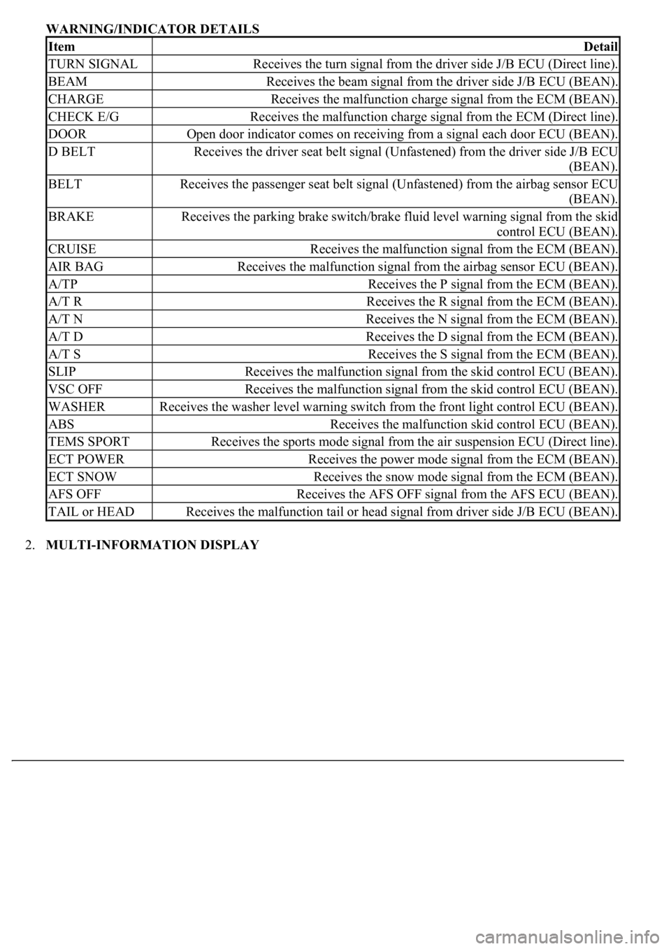
WARNING/INDICATOR DETAILS
2.MULTI-INFORMATION DISPLAY
ItemDetail
TURN SIGNALReceives the turn signal from the driver side J/B ECU (Direct line).
BEAMReceives the beam signal from the driver side J/B ECU (BEAN).
CHARGEReceives the malfunction charge signal from the ECM (BEAN).
CHECK E/GReceives the malfunction charge signal from the ECM (Direct line).
DOOROpen door indicator comes on receiving from a signal each door ECU (BEAN).
D BELTReceives the driver seat belt signal (Unfastened) from the driver side J/B ECU
(BEAN).
BELTReceives the passenger seat belt signal (Unfastened) from the airbag sensor ECU
(BEAN).
BRAKEReceives the parking brake switch/brake fluid level warning signal from the skid
control ECU (BEAN).
CRUISEReceives the malfunction signal from the ECM (BEAN).
AIR BAGReceives the malfunction signal from the airbag sensor ECU (BEAN).
A/TPReceives the P signal from the ECM (BEAN).
A/T RReceives the R signal from the ECM (BEAN).
A/T NReceives the N signal from the ECM (BEAN).
A/T DReceives the D signal from the ECM (BEAN).
A/T SReceives the S signal from the ECM (BEAN).
SLIPReceives the malfunction signal from the skid control ECU (BEAN).
VSC OFFReceives the malfunction signal from the skid control ECU (BEAN).
WASHERReceives the washer level warning switch from the front light control ECU (BEAN).
ABSReceives the malfunction skid control ECU (BEAN).
TEMS SPORTReceives the sports mode signal from the air suspension ECU (Direct line).
ECT POWERReceives the power mode signal from the ECM (BEAN).
ECT SNOWReceives the snow mode signal from the ECM (BEAN).
AFS OFFReceives the AFS OFF signal from the AFS ECU (BEAN).
TAIL or HEADReceives the malfunction tail or head signal from driver side J/B ECU (BEAN).
Page 1780 of 4500

ACTIVE TEST
Performing the ACTIVE TEST using the hand-held tester allows the meters, indicators and so on to operate
without parts removal. Performing the ACTIVE TEST as the first step of troubleshooting is one way to shorten
labor time.
It is possible to display the DATA LIST on hand-held tester during the ACTIVE TEST.
a. Connect the hand-held tester to DLC3.
b. Turn the ignition switch to the ON position.
c. From the display on tester, perform the "ACTIVE TEST".
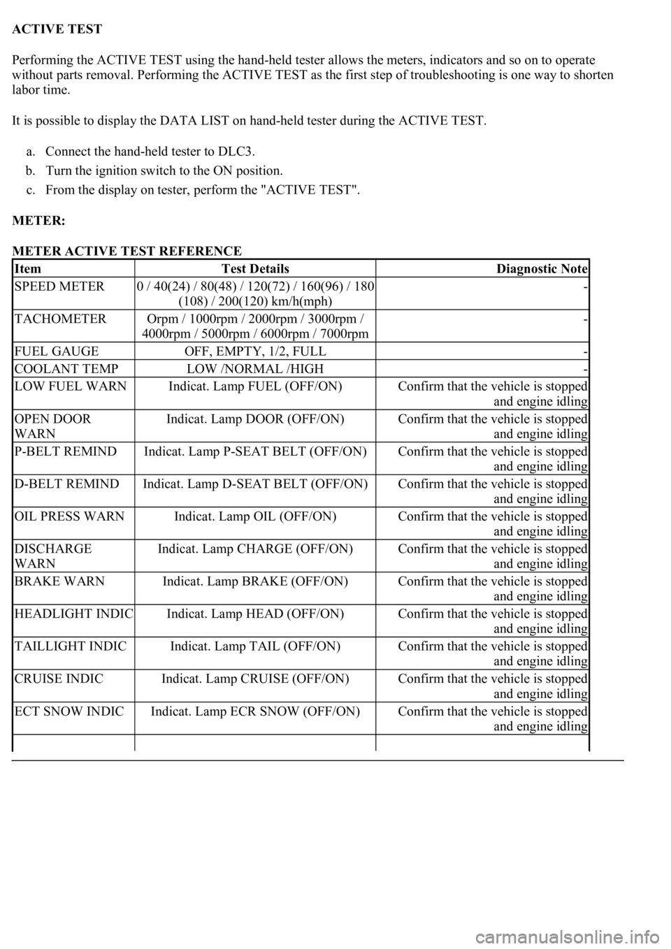
METER:
METER ACTIVE TEST REFERENCE
ItemTest DetailsDiagnostic Note
SPEED METER0 / 40(24) / 80(48) / 120(72) / 160(96) / 180
(108) / 200(120) km/h(mph)-
TACHOMETEROrpm / 1000rpm / 2000rpm / 3000rpm /
4000rpm / 5000rpm / 6000rpm / 7000rpm-
FUEL GAUGEOFF, EMPTY, 1/2, FULL-
COOLANT TEMPLOW /NORMAL /HIGH-
LOW FUEL WARNIndicat. Lamp FUEL (OFF/ON)Confirm that the vehicle is stopped
and engine idling
OPEN DOOR
WARNIndicat. Lamp DOOR (OFF/ON)Confirm that the vehicle is stopped
and engine idling
P-BELT REMINDIndicat. Lamp P-SEAT BELT (OFF/ON)Confirm that the vehicle is stopped
and engine idling
D-BELT REMINDIndicat. Lamp D-SEAT BELT (OFF/ON)Confirm that the vehicle is stopped
and engine idling
OIL PRESS WARNIndicat. Lamp OIL (OFF/ON)Confirm that the vehicle is stopped
and engine idling
DISCHARGE
WARNIndicat. Lamp CHARGE (OFF/ON)Confirm that the vehicle is stopped
and engine idling
BRAKE WARNIndicat. Lamp BRAKE (OFF/ON)Confirm that the vehicle is stopped
and engine idling
HEADLIGHT INDICIndicat. Lamp HEAD (OFF/ON)Confirm that the vehicle is stopped
and engine idling
TAILLIGHT INDICIndicat. Lamp TAIL (OFF/ON)Confirm that the vehicle is stopped
and engine idling
CRUISE INDICIndicat. Lamp CRUISE (OFF/ON)Confirm that the vehicle is stopped
and engine idling
ECT SNOW INDICIndicat. Lamp ECR SNOW (OFF/ON)Confirm that the vehicle is stopped
and engine idling