Page 1713 of 4500

Courtesy of TOYOTA MOTOR SALES, U.S.A., INC.
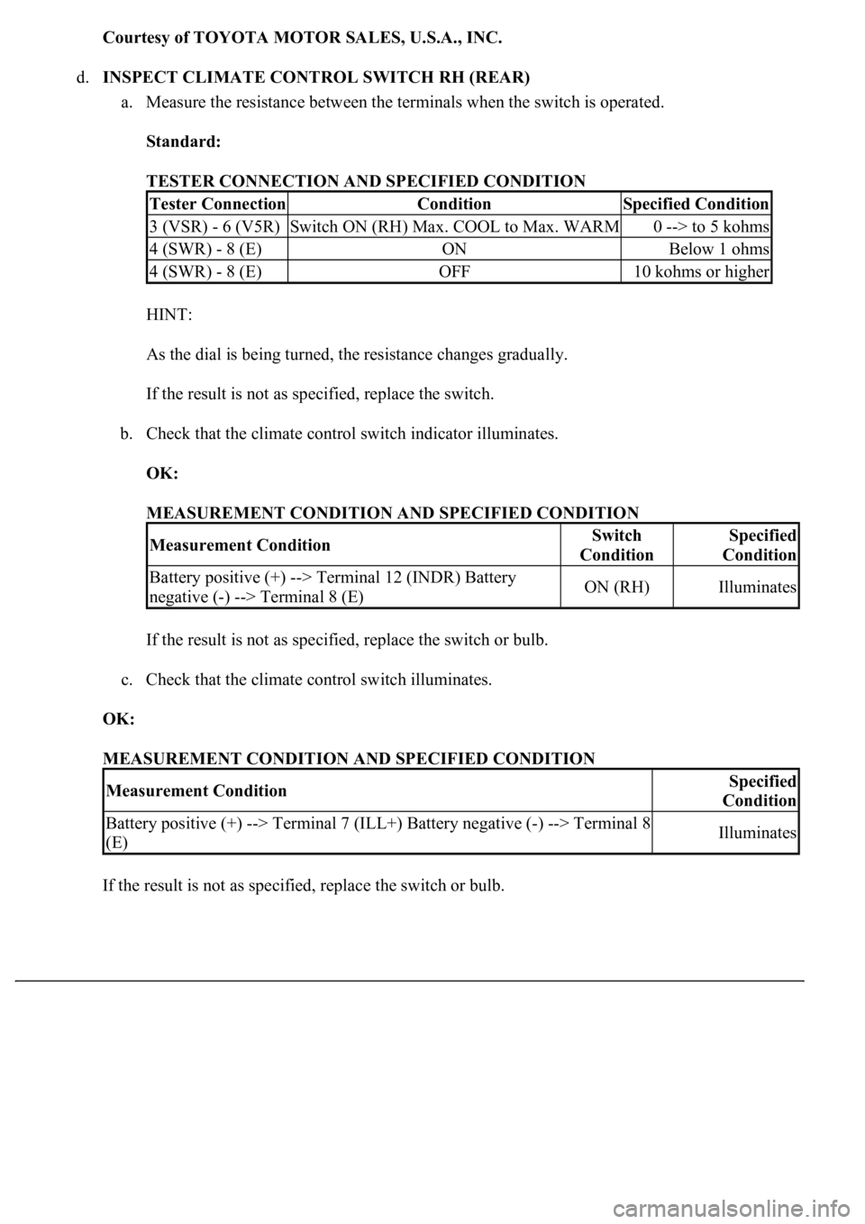
d.INSPECT CLIMATE CONTROL SWITCH RH (REAR)
a. Measure the resistance between the terminals when the switch is operated.
Standard:
TESTER CONNECTION AND SPECIFIED CONDITION
HINT:
As the dial is being turned, the resistance changes gradually.
If the result is not as specified, replace the switch.
b. Check that the climate control switch indicator illuminates.
OK:
MEASUREMENT CONDITION AND SPECIFIED CONDITION
If the result is not as specified, replace the switch or bulb.
c. Check that the climate control switch illuminates.
OK:
MEASUREMENT CONDITION AND SPECIFIED CONDITION
If the result is not as specified, replace the switch or bulb.
Tester ConnectionConditionSpecified Condition
3 (VSR) - 6 (V5R)Switch ON (RH) Max. COOL to Max. WARM0 --> to 5 kohms
4 (SWR) - 8 (E)ONBelow 1 ohms
4 (SWR) - 8 (E)OFF10 kohms or higher
Measurement ConditionSwitch
ConditionSpecified
Condition
Battery positive (+) --> Terminal 12 (INDR) Battery
negative (-) --> Terminal 8 (E)ON (RH)Illuminates
Measurement ConditionSpecified
Condition
Battery positive (+) --> Terminal 7 (ILL+) Battery negative (-) --> Terminal 8
(E)Illuminates
Page 2373 of 4500
Fig. 67: Disconnecting Toe Control Link From Axle Carrier
Courtesy of TOYOTA MOTOR SALES, U.S.A., INC.
12.SEPARATE SHOCK ABSORBER ASSY REAR LH
a. Remove the nut and disconnect the shock absorber arm from the axle carrier.
Page 2374 of 4500
Fig. 68: Removing Shock Absorber Arm Nut
Courtesy of TOYOTA MOTOR SALES, U.S.A., INC.
13.SEPARATE UPPER CONTROL ARM ASSY REAR LH
a. Loosen the nut to the top line of the bolt.
HINT:
Do not remove the nut.
b. Using SST, disconnect the upper control arm assy from the axle carrier.
SST 09628-0001 1
Page 2375 of 4500
Fig. 69: Disconnecting Upper Control Arm Assy From Axle Carrier
Courtesy of TOYOTA MOTOR SALES, U.S.A., INC.
14.SEPARATE REAR SUSPENSION ARM ASSY NO. 2 LH
a. Remove the nut.
b. Using SST, disconnect the suspension arm No. 2 from the axle carrier.
SST 09628-00011
Page 2376 of 4500
Fig. 70: Disconnecting Suspension Arm No. 2 From Axle Carrier
Courtesy of TOYOTA MOTOR SALES, U.S.A., INC.
15.DISCONNECT REAR DRIVE SHAFT ASSY LH
a. Using a plastic hammer, separate the drive shaft from the axle hub.
b. Remove the nut, and separate the upper control arm assy.
16.REMOVE REAR DRIVE SHAFT ASSY LH
a. Using SST, remove the rear drive shaft assy LH.
SST 09520-01010, 09520-24010 (09520-32040)
Page 2378 of 4500
Whether the inboard joint shaft is in contact with the pinion shaft or not can be known from the
sound or feeling when driving it in.
c. Install the drive shaft assy LH to the rear axle assy LH.
Fig. 72: Installing Rear Drive Shaft Assy LH To Rear Axle Assy LH
Courtesy of TOYOTA MOTOR SALES, U.S.A., INC.
19.TEMPORARILY TIGHTEN UPPER CONTROL ARM ASSY REAR LH
a. Temporarily tighten the upper control arm assy LH with a new nut.
Page 2379 of 4500
Fig. 73: Identifying Upper Control Arm Assy Rear LH Nut
Courtesy of TOYOTA MOTOR SALES, U.S.A., INC.
20.INSTALL SHOCK ABSORBER ASSY REAR LH
a. Install the shock absorber assy LH with the new nut.
Torque: 70 N.m (714 kgf.cm, 52 ft.lbf)
Page 2381 of 4500
Fig. 75: Identifying Rear Suspension Arm Assy No. 2 LH Nut
Courtesy of TOYOTA MOTOR SALES, U.S.A., INC.
22.INSTALL TOE CONTROL LINK SUB-ASSY LH
a. Install the toe control link assy LH with the new nut.
Torque: 50 N.m (510 kgf.cm, 37 ft.lbf)